EP0858128B1 - Connection system for high current carrying electrical conductors and method of manufacturing such connection system - Google Patents
Connection system for high current carrying electrical conductors and method of manufacturing such connection system Download PDFInfo
- Publication number
- EP0858128B1 EP0858128B1 EP98102025A EP98102025A EP0858128B1 EP 0858128 B1 EP0858128 B1 EP 0858128B1 EP 98102025 A EP98102025 A EP 98102025A EP 98102025 A EP98102025 A EP 98102025A EP 0858128 B1 EP0858128 B1 EP 0858128B1
- Authority
- EP
- European Patent Office
- Prior art keywords
- socket
- contact
- connection system
- housing
- conductor
- Prior art date
- Legal status (The legal status is an assumption and is not a legal conclusion. Google has not performed a legal analysis and makes no representation as to the accuracy of the status listed.)
- Expired - Lifetime
Links
Images

Classifications
-
- H—ELECTRICITY
- H01—ELECTRIC ELEMENTS
- H01R—ELECTRICALLY-CONDUCTIVE CONNECTIONS; STRUCTURAL ASSOCIATIONS OF A PLURALITY OF MUTUALLY-INSULATED ELECTRICAL CONNECTING ELEMENTS; COUPLING DEVICES; CURRENT COLLECTORS
- H01R13/00—Details of coupling devices of the kinds covered by groups H01R12/70 or H01R24/00 - H01R33/00
- H01R13/02—Contact members
- H01R13/10—Sockets for co-operation with pins or blades
-
- H—ELECTRICITY
- H01—ELECTRIC ELEMENTS
- H01R—ELECTRICALLY-CONDUCTIVE CONNECTIONS; STRUCTURAL ASSOCIATIONS OF A PLURALITY OF MUTUALLY-INSULATED ELECTRICAL CONNECTING ELEMENTS; COUPLING DEVICES; CURRENT COLLECTORS
- H01R13/00—Details of coupling devices of the kinds covered by groups H01R12/70 or H01R24/00 - H01R33/00
- H01R13/46—Bases; Cases
- H01R13/53—Bases or cases for heavy duty; Bases or cases for high voltage with means for preventing corona or arcing
-
- H—ELECTRICITY
- H01—ELECTRIC ELEMENTS
- H01R—ELECTRICALLY-CONDUCTIVE CONNECTIONS; STRUCTURAL ASSOCIATIONS OF A PLURALITY OF MUTUALLY-INSULATED ELECTRICAL CONNECTING ELEMENTS; COUPLING DEVICES; CURRENT COLLECTORS
- H01R2101/00—One pole
Definitions
- the invention relates to a connection system for high currents leading electrical conductors, in particular on transformers or Electric vehicle drive cables to be connected, with the characteristics of The preamble of claim 1.
- connection systems of this type are known from WO 95/28019.
- the contact socket parts are rolled from a board and either directly or by means of an insert and a compression sleeve with the cables to be connected. This results in low Manufacturing costs. However, it turns out in operation that at very high Currents and high operating voltages affect the electrical properties of the Connection system are not yet optimal.
- connection system improves the type mentioned, if possible while maintaining a inexpensive manufacture.
- this object is achieved by a connection system with the features of claim 1.
- Advantageous refinements and a manufacturing method are the subject of subclaims.
- the contact socket part is made in one piece from a solid part results in a significantly better contacting of the electrical conductor to be connected compared to the rolled circuit board of the known contact socket part.
- the contacting is improved by the reduced number of contact points to be produced.
- the connection system according to the invention can be used at significantly higher currents and significantly higher operating voltages than the known connection system. It is thus easily possible to use the connection system according to the invention in voltage ranges from 0.5 to 10 kV and current ranges from 50 to 800 A.
- the cables to be connected can have cross sections of 35 to 300 mm 2 .
- connection system according to the invention can be used both in stationary systems, for example on transformers, as well as in mobile Systems, such as electric vehicles and electric locomotives, in which due the vibrations place higher demands on the contact.
- the contact between the socket of the contact socket part and the Contact stud is preferably improved by having each tongue on its On the inside several, inwardly projecting, one line contact each resulting material batches. By increasing the number of Line contacts are provided with more current paths.
- the position of the line contacts on the tongues can only be on the edge, only in the Center or spread over the tongue surfaces.
- the the line contacts lots of material can be formed without cutting or cutting.
- a non-cutting formation of the line contacts can, for example, by bending of the tongues, either by enlarging or by Reduction of the circumferential radius of curvature.
- a cutting machine Line contacts can be formed, for example, by using a broach for the shaping of the material parts.
- the contact pressure of the tongues is improved by a spring that the socket encloses helically in the area of the tongues and their spring force radially works inwards.
- the spring can, for example, as a helical spring or be designed as a spring tension ring.
- the recording for the to be connected leads in the longitudinal direction of the socket, in particular with the The socket is aligned.
- different inner diameters of the Socket on the one hand and the receptacle on the other hand be provided so that the Machining from the solid part is easily possible.
- each of the intended shots is transverse is aligned to the longitudinal direction of the socket and is open.
- each intended receptacle is designed as a press sleeve.
- recordings with clamping screws are also possible.
- each intended contact socket part or each provided contact bolts each have an electrically insulating housing, the mutually associated housing forming a fluid and / or electrically tight connection are plugged into each other.
- the seal is done preferably by contact surfaces with little play, if necessary by additional sealing elements.
- connection pin forms the transformer connection while the contact socket part is provided in the plug.
- the connection can be penetrated deeper into the transformer housing be shifted, for example into a recess with an inner cone, and to lateral protection for this otherwise protruding part is achieved immediately become.
- the diameter of the housing, the Contact socket part and the contact pin and the length of the housing in The connection system can also do the longitudinal direction of the socket or bolt be protected from contact on the front.
- the interlocking housings can be locked by means of a Wire bracket can be achieved, for example, through openings in the outer This engages through the housing, resiliently abuts the inner housing and with Interlocking elements that interact on the outside of the inner Housing are provided at a point not used for sealing.
- the interlocking housings can also be locked, for example done by a swiveling lever on one housing, the spring-loaded engages in a locking lug on the other housing. With the types of locking mentioned, the connector can be used without Additional tools can be fixed in the socket and released again.
- the housing for the contact socket part is formed in two parts in the area of the receptacle.
- the necessary Housing seal between these two housing parts can be in one piece or also be in two parts, in the latter case one part each Housing part is assigned.
- the strain relief can form in the case of a two-part housing seal advantageously also in two parts, each with a part of the sealing ring one housing seal part is connected, for example in one piece is executed.
- the common division level of in this embodiment Housing, housing seal and sealing ring preferably runs in Longitudinal direction of the cable to be connected so that all parts are easily accessible are.
- the two housing parts are advantageously closed by a tubular body that at least partially on the two housing parts can be pushed on and, for example, non-positive or positive is held.
- Connection system is first a solid metal part with the Outer contours of the contact socket part pressed or by chill casting prepared. In this are a socket and the desired recordings for bored conductors to be connected.
- the intended for the line contacts Parts of material on the inside of the tongues are made from the inner wall of the Bush worked out, for example by bumping or in a preferred way by means of a broach.
- the socket is in tongues divided, for example by sawing or also with a broach.
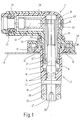
- Fig. 1 shows a section through the first embodiment.
- the first exemplary connection system consists of a whole with 1 designated plug and a socket designated as a whole with 2.
- the socket 2 has an essentially cylindrical, metallic Contact pin 4 and a tubular, open at one end, electrically insulating bolt housing 6.
- the bolt housing 6 is concentric with Contact pin 4 arranged and extends over most of its length away from this at a distance.
- the bolt housing 6 is partially inside a transformer filled with oil or inert gas.
- the bolt housing 6 has a flange on the outside of the transformer, which with the interposition of a Wall seal 10 rests on the outside of the transformer cover 8.
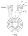
- Figure 1A shows a side view of the flange in cross section and Figure 1B shows a top view of the flange of the Transformer cover 8 out.
- the flange of the bolt housing 6 has its side 200 facing the transformer cover 8 has an annular shape Groove 250 for receiving the wall seal 10.
- the annular groove 250 points around the circumference and is directed radially inwards Bulges 251, which create space for the sealing Displacement of the wall seal 10.
- the bulges 251 can alternatively or also be directed radially outwards.
- the annular groove 250 furthermore has concentric elevations 253 on its bottom surface 252, which serve an improved seal.
- the flange of the bolt housing 6 on its facing away from the transformer cover 8 Page 259 another annular groove 260 for receiving another Seal for sealing against the cover 12.
- a cover 12 engages over the flange of the bolt housing 6 and is thus with the transformer cover 8 screwed that the wall seal 10th seals between the pin housing 6 and the transformer cover 8. With the the bolt housing 6 lockable cover 12 is in the middle Provided hole area, the edge of which at the transformer outer end of the Pin housing 6 is flush. The hole area and the Inner lateral surface of the bolt housing 6 has the same inner diameter.
- the bolt housing 6 is on the Contact pin 4 brought up.
- the bolt housing 6 lies over a short one cylindrical piece on the contact pin 4.
- By means of an Contact bolt 4 provided stop 4 'and one on a Contact bolt 4 provided thread screw nut 16 are the Contact bolt 4 and the bolt housing 6 connected to each other, wherein the O-rings 14 the contact pin 4 and the pin housing 6 against each other seal.
- the stop 4 ' is on the inside of the transformer and the nut 16 on the outside of the transformer intended.
- the contact pin 4 From the stop 4 'to its end facing the transformer the contact pin 4 has a thread 4 ′′.
- the stop 4 ' also serves as Installation for a connection 18 to a phase winding of the transformer.
- This connection 18 can be screwed onto the thread 4 ′′ Fixing nut 20 and a lock nut 22 can be fixed.
- As a counter to Screwing is at the end of the contact bolt 4 on the inside of the transformer Hexagon socket 24 provided.
- the plug 1 has a metallic contact socket part 31 and an electrical one insulating socket housing 33 made of plastic.
- One end of the Contact socket part 31 is designed as a socket 35.
- the longitudinal direction of the bushing is essentially cylindrical Interior of the socket 35 defined.
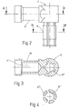
- FIG. 2 shows a side view of the contact socket part of FIG. 1.
- 3 and 4 show a section along the line III-III or IV-IV in Figure 2.
- the jacket area of the socket 35 consists of several, in Longitudinal socket extending tongues 35 ', each of which on their Has several, inwardly projecting material portions 35 '' on the inside.
- the bush 35 On its outside, the bush 35 is in the area of the tongues 35 ' helically enclosed by a contact spring 37, the spring force acts radially inwards.
- Each of the material parts preferably runs continuously over the entire inner length of the contact socket 35. This will make the contact performance of the Connection system, especially in the high voltage / high current range improved because the heat dissipation from local contact points is better dissipated becomes.
- the contact socket part 31 At the end facing away from the socket 35, the contact socket part 31 one protruding at right angles, i.e. transverse to the longitudinal direction of the socket extending arm 39 on.
- arm 39 In arm 39 is one towards the free end of the arm 39 opening 41 provided for a conductor to be connected, in the embodiment for a partially stripped cable.
- the Walls of the receptacle 41 formed as a press sleeve.
- the one to be connected So cable is by means of a press connection, for example one Hexagon pressing, electrically conductive with contact socket part 31 connectable.
- the contact socket part 31 is made of a solid part, so that the socket 35 together with tongues 35 'with the arm 39 carrying the receptacle is formed in one piece.
- the outer contours of the contact socket part 31 from a solid metal part worked out by pressing. In the longitudinal direction of the bush pierced the contact socket part 31. With a broach through that resulting bore is guided, the material parts 35 '' of the later Tongues 35 'worked out.
- the area of the female connector part 31, which later forms the bush 35 has a smaller outer diameter than the rest of the area in the longitudinal direction of the socket. The socket 35 can therefore can also be broken down into tongues 35 'using a broach.
- the formation of the tongues 35 'and the formation the material parts 35 '' can be done in a single broaching process.
- the outer surface of the bush 35 can also be turned circumferentially to be edited. In this case, the turning process and then the clearing process.
- the receptacle 41 is created by drilling a blind hole or one up to that in the longitudinal direction of the socket Hole reaching hole in the arm 39.
- the contact socket part 31 is made rod-shaped material, as shown in Fig. 2A.
- the socket 35 and the receptacle 41 are inserted as described above.
- the material parts 35 ′′ are passed through Butting or by contour turning and the tongues 35 'by sawing of the slots made.
- the rod-shaped material on opposite sides over a certain length through incisions or millings 200 in its Cross-sectional area reduced.
- the reduction in cross-section can also be applied to others Way, for example, the blank of the used rod-shaped material at the beginning of the manufacturing process have correspondingly tapered central area.
- a right-angled bending of the contact socket part 31 in the area of the reduced Cross section as shown in Fig. 2B.
- the socket housing 33 encloses the contact socket part 31 in the area of Socket 35 over its entire circumference, being in the longitudinal direction of the socket something survives through the socket 35.
- the area of the arm 39 surrounds the socket housing 33, the branch and the arm 39 only in the manner of a Half-shell, being in the direction of the arm 39 beyond its free end is extended.
- the two housing parts 33 and 43 lie against one another within one plane on. This level is referred to below as the division level.
- the butt edges of the housing parts 33 and 43 face each other in the division plane aligned grooves, in each half of a housing seal 45 is inserted.
- Each half of the symmetrical through the division plane two-part housing seal 45 is thus one of the two housing parts 33 or 43 is assigned.
- the abutting edges of the housing parts 33 and 43 are preferably designed as a labyrinth seal.
- the two housing parts 33 and 43 have receptacles for one in Extension of the arm 39 arranged concentrically to the receptacle 41 Sealing ring 47 on.
- the sealing ring 47 is open from its inner diameter the diameter of the insulation of the cable to be connected.
- the sealing ring 47 is also divided by the plane of division into two symmetrical Half divided.
- Each of the half-ring-shaped halves of the sealing ring 47 is integrally formed with one of the halves of the housing seal 45.
- the sealing ring 47 has annular beads on its outer circumference, so when closing the housing parts 33, 43 space to displace the Sealing ring is present. This creates the closing forces for the two Housing parts 33, 43 reduced and the sealing effect of the sealing ring 47 elevated.
- the housing seal 45 and the sealing ring 47 are each made in one piece.
- the design of the housing seal is particularly advantageous 45 and the sealing ring 47 as a single seal, that is to say in one piece, since this further increases the number of components of the connection system is reduced and thus the manufacture, assembly and spare parts inventory is more cost-effective.
- This one-piece seal points on cable-side end also has annular beads on the outer circumference.
- a cylindrical tubular body 49 is above the two housing parts 33 and 43 postponed.
- the dimensions of the housing parts and seals are so chosen that the housing seal 45 and the sealing ring 47 the two housing parts 33 and 43 to the outside and to Seal the cable.
- the sealing ring 47 serves for strain relief, since it when the cable is bent, the cable sheath slips out, i.e. one Relative movement of the cable insulation compared to the metallic conductor prevented.
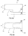
- FIG. 6A shows a side view of the cylindrical tubular body 49.
- the cylindrical tubular body 49 has in an advantageous embodiment of the connection system extending in the longitudinal direction Cantilever 670, which is in contact with the cover 12 and one Support of the plug with the cable connected in particular serves while plugged in.
- the tubular body is preferably an impact-resistant and electrically insulating Plastic used.
- the cylindrical tubular body 49 has a reduced opening width 671, which only is slightly larger than the diameter of the connected cable.
- the outer shape of the edges of this end of the cylindrical tubular body 49 is almost semicircular 672 or spherical in order to damage the Prevent operators and cable insulation effectively.
- FIG. 6B shows a top view of the cylindrical tubular body 49.
- the cylindrical tubular body 49 on the receptacle 12 by screws 680 attached, for example by two Allen screws Stainless steel.
- the screw fastening is preferably carried out in the area of the position the contact socket 31 to secure attachment and fixation of the To ensure contact socket 31.
- plug 1 is inserted into socket 2 introduced.
- the electrical contact is improved by the force of the contact spring 37, which the tongues 35 'in addition to the Contact pin 4 presses on.
- the socket housing 33 is manufactured Plug connection in the area of the socket 35 fluid-tight on the inner wall of the Bolt housing 6 on due to a small game. By doing so at the same time generated long creepage distance and an additional one at the end of the These are socket housing 33 provided in an annular groove Socket housing 33 and the bolt housing 6 are also electrically tight locked.
- One between the pin housing 6 and the cover 12 in one corresponding recess movable wire bracket 50 is in the manufactured Plug connection to the area of the socket housing 33 which resiliently between the sealing part of the socket housing 33 and the branch of the Armes 39 is located.
- the wire bracket 50 also engages in the socket housing 33 provided locking elements and thereby locks the connector 1 with the Socket 2.
- a lock is only permitted if the on Socket housing 33 provided for coding the transformer phase Coding ring 53 with corresponding coding elements 54 of the Cover 12 interacts. This interaction is through a Form-fit of surveys and recesses achieved for each Pair of plug 1 and socket 2 different in Extend the longitudinal and circumferential directions of the bushing.
- the Coding or reverse polarity protection by integrally on the socket housing 33 attached lugs, which in corresponding recesses of the cover 12th intervention.
- two noses are used, respectively the coding at a certain angular distance on a circumference Circular path are attached.
- the two noses can still have different lateral dimensions or heights.
- an anti-twist device for the connection between the Plug 1 and receptacle 12 may be provided.
- the mechanical Color coding can also be carried out, for example, by colored rings at the joint of the two Housing parts (33, 43) are inserted.
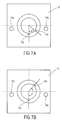
- FIGS. 7A and 7B each show a top view of the cover 12 two different codes for different phase connections.
- the two recesses 791, 792 close one Angle ⁇ of 54 °.
- the two close Recesses 791, 792 an angle ⁇ of 138 °. More possible Angular distances are 82 °, 110 °, 166 ° and their 360 ° complementary angles.
- the socket housing 33 is preferably over the cylindrical Pipe body 49 by means of 794 in the threaded holes engaging screws 680 firmly connected to the cover.
- the cover 12 in turn is preferably not shown Screw connections firmly connected to the transformer cover 8.
- Phase marking can be permanently applied, for example by engraving or material-removing or material-displacing laser marking. Plastic, aluminum or steel comes in as the material for the cover 12 Consideration.
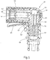
- the third embodiment of the connection system according to the invention 5 is intended for use in electric vehicle drives. So far the third embodiment with the first embodiment matches, reference numerals higher by 100 are used in the following.
- FIG. 5 shows a section through the second embodiment.
- a connector 101 is shown, which has a contact socket part 131 a socket 135.
- the socket 135 consists of several in Longitudinal tongues 135 ', as in the first Embodiment are formed. Points transverse to the longitudinal direction of the socket the contact socket part 131 corresponding to the first embodiment an arm 139 with a receptacle 141.
- the contact socket part 131 will enclosed by a socket housing 133, which as in the first Embodiment is formed in the region of the arm 139 half-shell and covered by a half-shell-shaped socket housing cover 143 becomes.
- each a part of the housing seal 145 with a part of the sealing ring 147 is formed in one piece.
- a tubular body 149 is over the two housing parts 133 and 143 postponed.
- FIG. 5 Only the pin housing 106 of the plug socket is shown in FIG. 5.
- a toggle 155 is pivotally mounted at right angles to the longitudinal direction of the socket and at right angles to the direction of the Arms 139 are two on the tubular body 149 on the outside opposite pins are provided on which a toggle 155 is pivotally mounted.
- the lever 155 is on that side of the Tubular body 149 arranged, the area surrounding the socket 135 facing the socket housing 133.
- a two-leg curved Leaf spring 157 rests with one leg on the tubular body 159 and instructs) free end of this leg on a nose, with which it through an opening of the Pipe body 149 engages in a recess in the socket housing 133. With the other leg of the spring 157 is located on one leg of the lever 155 on.
Description
Die Erfindung betrifft ein Verbindungssystem für hohe Ströme führende elektrische Leiter, insbesondere an Transformatoren oder Elektrofahrzeugantriebe anzuschließende Kabel, mit den Merkmalen des Oberbegriffs des Anspruches 1.The invention relates to a connection system for high currents leading electrical conductors, in particular on transformers or Electric vehicle drive cables to be connected, with the characteristics of The preamble of claim 1.
Verbindungssysteme dieser Art sind aus der WO 95/28019 bekannt. Die Kontaktbuchsenteile sind dabei aus einer Platine gerollt und entweder direkt oder mittels eines Einlegeteils und einer Preßhülse mit dem anzuschließenden Kabel verbunden. Hierdurch ergeben sich niedrige Herstellungskosten. Es zeigt sich jedoch im Betrieb, daß bei sehr hohen Strömen und hohen Betriebsspannungen die elektrischen Eigenschaften des Verbindungssystems noch nicht optimal sind.Connection systems of this type are known from WO 95/28019. The contact socket parts are rolled from a board and either directly or by means of an insert and a compression sleeve with the cables to be connected. This results in low Manufacturing costs. However, it turns out in operation that at very high Currents and high operating voltages affect the electrical properties of the Connection system are not yet optimal.
Der Erfindung liegt daher die Aufgabe zugrunde, ein Verbindungssystem der eingangs genannten Art zu verbessern, möglichst unter Beibehaltung einer kostengünstigen Herstellung. Diese Aufgabe wird erfindungsgemäß gelöst durch ein Verbindungssystem mit den Merkmalen des Anspruches 1. Vorteilhafte Ausgestaltungen sowie ein Herstellungsverfahren sind Gegenstand der Unteransprüche.The invention is therefore based on the object of a connection system to improve the type mentioned, if possible while maintaining a inexpensive manufacture. According to the invention, this object is achieved by a connection system with the features of claim 1. Advantageous refinements and a manufacturing method are the subject of subclaims.
Dadurch, daß das Kontaktbuchsenteil einstückig aus einem massiven Teil hergestellt ist, ergibt sich gegenüber der gerollten Platine des bekannten Kontaktbuchsenteils eine deutlich bessere Kontaktierung des anzuschließenden elektrischen Leiters. Gegenüber dem bekannten Kontaktbuchsenteil mit Einlegeteil und zwei weiteren Preßstellen wird die Kontaktierung verbessert durch die reduzierte Anzahl von herzustellenden Kontaktstellen. Aufgrund der verbesserten Kontaktierung kann das erfindungsgemäße Verbindungssystem bei wesentlich höheren Strömen und wesentlich höheren Betriebsspannungen eingesetzt werden als das bekannte Verbindungssystem. So ist es ohne weiteres möglich, das erfindungsgemäße Verbindungssystem in Spannungsbereichen von 0,5 bis 10 kV und Strombereichen von 50 bis 800 A einzusetzen. Je nach Ausführungsform können die anzuschließenden Kabel Querschnitte von 35 bis 300 mm2 aufweisen.The fact that the contact socket part is made in one piece from a solid part results in a significantly better contacting of the electrical conductor to be connected compared to the rolled circuit board of the known contact socket part. Compared to the known contact socket part with insert and two further pressing points, the contacting is improved by the reduced number of contact points to be produced. Because of the improved contacting, the connection system according to the invention can be used at significantly higher currents and significantly higher operating voltages than the known connection system. It is thus easily possible to use the connection system according to the invention in voltage ranges from 0.5 to 10 kV and current ranges from 50 to 800 A. Depending on the embodiment, the cables to be connected can have cross sections of 35 to 300 mm 2 .
Das erfindungsgemäße Verbindungssystem kann eingesetzt werden sowohl in stationären Systemen, beispielsweise an Transformatoren, als auch in mobilen Systemen, wie Elektrofahrzeugen und Elektrolokomotiven, in denen aufgrund der Vibrationen höhere Anforderungen an die Kontaktierung gestellt werden.The connection system according to the invention can be used both in stationary systems, for example on transformers, as well as in mobile Systems, such as electric vehicles and electric locomotives, in which due the vibrations place higher demands on the contact.
Die Kontaktierung zwischen der Buchse des Kontaktbuchsenteils und dem Kontaktbolzen wird vorzugsweise dadurch verbessert, daß jede Zunge auf ihrer Innenseite mehrere, nach innen vorspringende, je einen Linienkontakt ergebenden Materialpartien aufweist. Durch diese Erhöhung der Anzahl der Linienkontakte werden mehr Strompfade zur Verfügung gestellt. The contact between the socket of the contact socket part and the Contact stud is preferably improved by having each tongue on its On the inside several, inwardly projecting, one line contact each resulting material batches. By increasing the number of Line contacts are provided with more current paths.
Die Position der Linienkontakte auf den Zungen kann nur am Rand, nur in der Mitte oder über die Zungenflächen verteilt erfolgen. Die die Linienkontakte bildenden Materialpartien können spanlos oder spanabhebend gebildet werden. Eine spanlose Bildung der Linienkontakte kann beispielsweise durch Verbiegen der Zungen erfolgen, und zwar entweder durch Vergrößerung oder durch Verkleinerung des umfänglichen Krümmungsradius. Eine spanabhebende Bildung der Linienkontakte kann beispielsweise durch Einsatz einer Räumnadel für die Ausformung der Materialpartien erfolgen. Durch das Vorsehen der Materialpartien auf den Zungen der Buchse ist das aus dem Stand der Technik bekannte und aufwendige Schlitzen des Steckerteils entbehrlich.The position of the line contacts on the tongues can only be on the edge, only in the Center or spread over the tongue surfaces. The the line contacts lots of material can be formed without cutting or cutting. A non-cutting formation of the line contacts can, for example, by bending of the tongues, either by enlarging or by Reduction of the circumferential radius of curvature. A cutting machine Line contacts can be formed, for example, by using a broach for the shaping of the material parts. By providing the Parts of the material on the tongues of the bushing are from the prior art known and expensive slots of the plug part can be dispensed with.
Der Kontaktdruck der Zungen wird durch eine Feder verbessert, die die Buchse im Bereich der Zungen schraubenförmig umschließt und deren Federkraft radial nach innen wirkt. Die Feder kann dabei beispielsweise als Schraubenfeder oder als Federspannring ausgeführt sein.The contact pressure of the tongues is improved by a spring that the socket encloses helically in the area of the tongues and their spring force radially works inwards. The spring can, for example, as a helical spring or be designed as a spring tension ring.
Grundsätzlich ist es herstellungstechnisch möglich, daß die Aufnahme für den anzuschließenden Leiter in Buchsenlängsrichtung verläuft, insbesondere mit der Buchse fluchtet. Beispielsweise können unterschiedliche Innendurchmesser der Buchse einerseits und der Aufnahme andererseits vorgesehen sein, so daß die Bearbeitung aus dem massiven Teil heraus problemlos möglich ist. Je nach Einsatzort des Verbindungssystems oder der Anzahl der anzuschließenden Leiter kann es von Vorteil sein, wenn jede der vorgesehenen Aufnahmen quer zur Buchsenlängsrichtung ausgerichtet und geöffnet ist. Vorteilhafterweise ist dabei jede vorgesehene Aufnahme als Preßhülse ausgebildet. Es sind jedoch beispielsweise auch Aufnahmen mit Klemmschrauben möglich.Basically, it is technically possible that the recording for the to be connected leads in the longitudinal direction of the socket, in particular with the The socket is aligned. For example, different inner diameters of the Socket on the one hand and the receptacle on the other hand be provided so that the Machining from the solid part is easily possible. Depending on Location of the connection system or the number of to be connected Heads can be advantageous if each of the intended shots is transverse is aligned to the longitudinal direction of the socket and is open. It is advantageous each intended receptacle is designed as a press sleeve. However, there are For example, recordings with clamping screws are also possible.
Zum Schutz des Verbindungssystems vor äußeren Einflüssen, der einzelnen Steckverbindungen untereinander im Fall mehrerer Steckverbindungen sowie dem Schutz des Bedieners vor Berührungen während des Betriebs ist vorteilhafterweise für jedes vorgesehene Kontaktbuchsenteil oder jeden vorgesehenen Kontaktbolzen je ein elektrisch isolierendes Gehäuse vorhanden, wobei die einander zugeordneten Gehäuse unter Bildung einer fluid- und/oder elektrisch dichten Verbindung ineinander steckbar sind. Die Dichtung erfolgt vorzugsweise durch Anlageflächen mit geringem Spiel, gegebenenfalls durch zusätzliche Dichtungselemente.To protect the connection system from external influences, the individual Plug connections with each other in the case of multiple plug connections as well protection of the operator against contact during operation advantageously for each intended contact socket part or each provided contact bolts each have an electrically insulating housing, the mutually associated housing forming a fluid and / or electrically tight connection are plugged into each other. The seal is done preferably by contact surfaces with little play, if necessary by additional sealing elements.
Beim Einsatz des erfindungsgemäßen Verbindungssystems an Transformatoren bildet der Kontaktbolzen den Transformatoranschluß, während das Kontaktbuchsenteil im Stecker vorgesehen ist. Gegenüber den genormten Durchführungen kann der Anschluß tiefer ins Transformatorengehäuse hinein verlagert werden, beispielsweise in eine Vertiefung mit Innenkonus, und zu gleich ein seitlicher Schutz für dieses ansonsten überstehende Teil erreicht werden. Bei geeigneter Wahl der Durchmesser der Gehäuse, des Kontaktbuchsenteils und des Kontaktbolzens sowie der Länge der Gehäuse in Buchsen- bzw. Bolzenlängsrichtung kann das Verbindungssystem auch stirnseitig vor Berührungen geschützt werden.When using the connection system according to the invention on transformers the contact pin forms the transformer connection while the contact socket part is provided in the plug. Compared to the standardized The connection can be penetrated deeper into the transformer housing be shifted, for example into a recess with an inner cone, and to lateral protection for this otherwise protruding part is achieved immediately become. With a suitable choice of the diameter of the housing, the Contact socket part and the contact pin and the length of the housing in The connection system can also do the longitudinal direction of the socket or bolt be protected from contact on the front.
Eine Verriegelung der ineinandergesteckten Gehäuse kann mittels eines Drahtbügels erreicht werden, der beispielsweise durch Öffnungen des äußeren Gehäuses dieses durchgreift, federnd am inneren Gehäuse anliegt und mit Rastelementen zusammenwirkt, welche an der Außenseite des inneren Gehäuses an einer nicht zur Abdichtung dienenden Stelle vorgesehen sind. Die Verriegelung der ineinander gesteckten Gehäuse kann beispielsweise auch erfolgen durch einen schwenkbaren Hebel auf dem einen Gehäuse, der federbelastet in eine Rastnase auf dem anderen Gehäuse eingreift. Mit den genannten Arten der Verriegelung kann der Stecker ohne Zusatzwerkzeug in der Steckbuchse festgelegt und wieder gelöst werden. The interlocking housings can be locked by means of a Wire bracket can be achieved, for example, through openings in the outer This engages through the housing, resiliently abuts the inner housing and with Interlocking elements that interact on the outside of the inner Housing are provided at a point not used for sealing. The interlocking housings can also be locked, for example done by a swiveling lever on one housing, the spring-loaded engages in a locking lug on the other housing. With the types of locking mentioned, the connector can be used without Additional tools can be fixed in the socket and released again.
Für eine vereinfachte Montage des das Kontaktbuchsenteil enthaltenden Steckers und für eine leichtere Zugänglichkeit des angeschlossenen Leiters im Bereich der Aufnahme, welche die einzige nicht vorgefertigte Kontaktstelle im Stecker bildet, ist es von Vorteil, wenn das Gehäuse für das Kontaktbuchsenteil im Bereich der Aufnahme zweiteilig ausgebildet ist. Die notwendige Gehäusedichtung zwischen diesen beiden Gehäuseteilen kann einteilig oder ebenfalls zweiteilig sein, wobei in letzterem Fall je ein Teil je einem Gehäuseteil zugeordnet ist. Für die Gehäusedichtung bietet sich ein leicht verformbares Material mit Außenbeschichtung an, beispielsweise ein Schaumstoff, der sowohl dichten als auch sich in seiner Form den Gehäuseteilen anpassen kann. Ein zwischen dem Gehäuse und dem anzuschließenden Leiter vorsehbarer Dichtungsring, der zugleich auch ein Teil der Zugentlastung bilden kann, ist im Falle einer zweiteiligen Gehäusedichtung vorteilhafterweise ebenfalls zweiteilig, wobei je ein Teil des Dichtungsrings mit je einem Gehäusedichtungsteil verbunden ist, beispielsweise einstückig ausgeführt ist. Die in dieser Ausführungsform gemeinsame Teilungsebene von Gehäuse, Gehäusedichtung und Dichtungsring verläuft vorzugsweise in Längsrichtung des anzuschließenden Kabels, so daß alle Teile leicht zugänglich sind. Das Verschließen der beiden Gehäuseteile erfolgt vorteilhafterweise durch einen Rohrkörper, der auf die beiden Gehäuseteile zumindest teilweise aufschiebbar ist und beispielsweise kraftschlüssig oder formschlüssig festgehalten wird.For a simplified assembly of the one containing the contact socket part Connector and for easier access to the connected conductor in the Area of the recording, which is the only non-prefabricated contact point in the Forms plug, it is advantageous if the housing for the contact socket part is formed in two parts in the area of the receptacle. The necessary Housing seal between these two housing parts can be in one piece or also be in two parts, in the latter case one part each Housing part is assigned. For the housing seal, it is easy deformable material with an outer coating, for example a Foam that is both dense and in shape Can adjust housing parts. One between the case and the connectable head of the predictable sealing ring, which is also a part The strain relief can form in the case of a two-part housing seal advantageously also in two parts, each with a part of the sealing ring one housing seal part is connected, for example in one piece is executed. The common division level of in this embodiment Housing, housing seal and sealing ring preferably runs in Longitudinal direction of the cable to be connected so that all parts are easily accessible are. The two housing parts are advantageously closed by a tubular body that at least partially on the two housing parts can be pushed on and, for example, non-positive or positive is held.
Bei der Herstellung eines Kontaktbuchsenteils für das erfindungsgemäße Verbindungssystem wird zunächst ein massives Metallteil mit den Außenkonturen des Kontaktbuchsenteils gepreßt oder durch Kokillenguß angefertigt. In dieses werden eine Buchse und die gewünschten Aufnahmen für anzuschließende Leiter gebohrt. Die für die Linienkontakte vorgesehenen Materialpartien auf der Innenseite der Zungen werden aus der Innenwand der Buchse herausgearbeitet, beispielsweise durch Stoßen oder in einer bevorzugten Weise mittels einer Räumnadel. Die Buchse wird in Zungen zerteilt, beispielsweise durch Sägen oder ebenfalls mittels einer Räumnadel.In the manufacture of a contact socket part for the invention Connection system is first a solid metal part with the Outer contours of the contact socket part pressed or by chill casting prepared. In this are a socket and the desired recordings for bored conductors to be connected. The intended for the line contacts Parts of material on the inside of the tongues are made from the inner wall of the Bush worked out, for example by bumping or in a preferred way by means of a broach. The socket is in tongues divided, for example by sawing or also with a broach.
Im folgenden ist die Erfindung anhand von in den Zeichnungen dargestellten Ausführungsbeispielen näher erläutert. Es zeigen
- Fig. 1
- einen Schnitt durch ein erstes Ausführungsbeispiel,
- Fig. 1A
- eine Seitenansicht des Flansches im Querschnitt,
- Fig. 1B
- eine Aufsicht auf den Flansch,
- Fig. 2
- eine Seitenansicht des Kontaktbuchsenteils der Fig. 1,
- Fig. 2A
- eine teilweise aufgeschnittene Seitenansicht eines zweiten Ausführungsbeispiels vor dem Abbiegen,
- Fig. 2B
- zeigt das zweite Ausführungsbeispiel der Fig. 2A nach dem Abbiegen,
- Fig. 3
- einen Schnitt nach der Linie III-III in Fig. 2,
- Fig. 4
- einen Schnitt nach der Linie IV-IV in Fig. 2,
- Fig. 5
- einen Schnitt durch ein drittes Ausführungsbeispiel,
- Fig. 6A
- eine Seitenansicht des zylindrischen Rohrkörpers,
- Fig. 6B
- eine Aufsicht auf den zylindrischen Rohrkörper,
- Fig. 7A
- eine Aufsicht auf die Abdeckung mit einer ersten Kodierung,
- Fig. 7B
- eine Aufsicht auf die Abdeckung mit einer zweiten Kodierung.
- Fig. 1
- 2 shows a section through a first exemplary embodiment,
- Fig. 1A
- a side view of the flange in cross section,
- Figure 1B
- a view of the flange,
- Fig. 2
- 2 shows a side view of the contact socket part of FIG. 1,
- Figure 2A
- a partially cut side view of a second embodiment before turning,
- Figure 2B
- shows the second embodiment of FIG. 2A after turning,
- Fig. 3
- 2 shows a section along the line III-III in FIG. 2,
- Fig. 4
- a section along the line IV-IV in Fig. 2,
- Fig. 5
- 2 shows a section through a third exemplary embodiment,
- Figure 6A
- a side view of the cylindrical tube body,
- Figure 6B
- a top view of the cylindrical tube body,
- Figure 7A
- a top view of the cover with a first coding,
- Figure 7B
- a top view of the cover with a second coding.
Die Fig. 1 zeigt einen Schnitt durch das erste Ausführungsbeispiel.
Das erste beispielshafte Verbindungssystem besteht aus einem als Ganzes mit 1
bezeichneten Stecker und einer als Ganzes mit 2 bezeichneten Steckbuchse.
Die Steckbuchse 2 weist einen im wesentlichen zylindrischen, metallischen
Kontaktbolzen 4 und ein rohrförmiges, an einer Stirnseite offenes, elektrisch
isolierendes Bolzengehäuse 6 auf. Das Bolzengehäuse 6 ist konzentrisch zum
Kontaktbolzen 4 angeordnet und verläuft über den größten Teil seiner Länge
hinweg in einem Abstand zu diesem. Über eine Öffnung in einem
Transformatorendeckel 8 ist das Bolzengehäuse 6 teilweise in das Innere eines
mit Öl oder Schutzgas gefüllten Transformators eingeführt. Das Bolzengehäuse
6 weist trafoaußenseitig einen Flansch auf, welcher unter Zwischenlage einer
Wanddichtung 10 an der Außenseite des Tranformatorendeckels 8 anliegt.Fig. 1 shows a section through the first embodiment.
The first exemplary connection system consists of a whole with 1
designated plug and a socket designated as a whole with 2.
The
Die Figur 1A zeigt eine Seitenansicht des Flansches im Querschnitt und
die Figur 1B zeigt eine Aufsicht auf den Flansch von dem
Transformatorendeckel 8 aus. Der Flansch des Bolzengehäuses 6 weist auf
seiner dem Transformatordeckel 8 zugewandten Seite 200 eine ringförmige
Nut 250 für die Aufnahme der Wanddichtung 10 auf. Die ringförmige Nut 250
weist über den Umfang verteilte und radial nach innen gerichtete
Ausbuchtungen 251 auf, die beim Abdichten Raum schaffen für die
Verdrängung der Wanddichtung 10. Die Ausbuchtungen 251 können alternativ
oder ergänzend auch radial nach außen gerichtet sein. Die ringförmige Nut 250
weist weiterhin auf ihrer Bodenfläche 252 konzentrische Erhebungen 253 auf,
die einer verbesserten Abdichtung dienen. Darüber hinaus weist der Flansch
des Bolzengehäuses 6 auf seiner dem Transformatordeckel 8 abgewandten
Seite 259 eine weitere ringförmige Nut 260 für die Aufnahme einer weiteren
Dichtung für die Abdichtung gegenüber der Abdeckung 12 auf.Figure 1A shows a side view of the flange in cross section and
Figure 1B shows a top view of the flange of the
Transformer cover 8 out. The flange of the
Eine Abdeckung 12 übergreift den Flansch des Bolzengehäuses 6 und ist so mit
dem Transformatorendeckel 8 verschraubbar, daß die Wanddichtung 10
zwischen Bolzengehäuse 6 und Transformatorendeckel 8 abdichtet. Bei der mit
dem Bolzengehäuse 6 verriegelbaren Abdeckung 12 ist in der Mitte ein
Lochbereich vorgesehen, dessen Berandung am trafoaußenseitigen Ende des
Bolzengehäuses 6 fluchtend anliegt. Dabei weisen der Lochbereich und die
Innenmantelfläche des Bolzengehäuses 6 den gleichen Innendurchmesser auf.A
An seinem trafoinnenseitigen Ende ist das Bolzengehäuse 6 an den
Kontaktbolzen 4 herangeführt. Dabei liegt das Bolzengehäuse 6 über ein kurzes
zylindrisches Stück am Kontaktbolzen 4 an. In diesem zylindrischen Stück sind
zwei O-Ringe 14 in Ringnuten des Kontaktbolzens 4 eingelegt. Mittels eines am
Kontaktbolzen 4 vorgesehenen Anschlages 4' und einer auf ein am
Kontaktbolzen 4 vorgesehenes Gewinde aufschraubbaren Mutter 16 sind der
Kontaktbolzen 4 und das Bolzengehäuse 6 miteinander verbunden, wobei
die O-Ringe 14 den Kontaktbolzen 4 und das Bolzengehäuse 6 gegeneinander
abdichten. Zugleich ist dadurch der trafoaußenseitigen Bereich des
Kontaktbolzens 4 gegenüber dem Inneren des Transformators abgedichtet.
Der Anschlag 4' ist trafoinnenseitig und die Mutter 16 trafoaußenseitig
vorgesehen. Vom Anschlag 4' ab bis zu seinem trafoinnenseitigen Ende weist
der Kontaktbolzen 4 ein Gewinde 4'' auf. Der Anschlag 4' dient zugleich als
Anlage für eine Verbindung 18 zu einer Phasenwickelung des Transformators.
Diese Verbindung 18 ist mittels einer auf das Gewinde 4'' aufschraubbaren
Befestigungsmutter 20 und einer Kontermutter 22 festlegbar. Als Gegenhalt zum
Schrauben ist am trafoinnenseitigen Ende des Kontaktbolzens 4 stirnseitig ein
Innensechskant 24 vorgesehen.At its transformer inside end, the
Der Stecker 1 weist ein metallisches Kontaktbuchsenteil 31 und ein elektrisch
isolierendes Buchsengehäuse 33 aus Kunststoff auf. Das eine Ende des
Kontaktbuchsenteiles 31 ist als Buchse 35 ausgebildet.
Die Buchsenlängsrichtung ist durch den im wesentlichen zylindrischen
Innenraum der Buchse 35 definiert.The plug 1 has a metallic
Die Figur 2 zeigt eine Seitenansicht des Kontaktbuchsenteils der Figur 1.
Die Figur 3 bzw. 4 zeigt einen Schnitt nach der Linie III-III bzw. IV-IV in
Figur 2. Der Mantelbereich der Buchse 35 besteht aus mehreren, sich in
Buchsenlängsrichtung erstreckenden Zungen 35', von denen jede auf ihrer
Innenseite mehrere, nach innen vorspringende Materialpartien 35'' aufweist.
Auf ihrer Außenseite ist die Buchse 35 im Bereich der Zungen 35'
schraubenförmig von einer Kontaktfeder 37 umschlossen, deren Federkraft
radial nach innen wirkt.FIG. 2 shows a side view of the contact socket part of FIG. 1.
3 and 4 show a section along the line III-III or IV-IV in
Figure 2. The jacket area of the
Jede der Materialpartien verläuft vorzugsweise durchgehend über die gesamte
innere Länge der Kontaktbuchse 35. Dadurch wird die Kontaktleistung des
Verbindungssystems gerade im Hochspannung-/Hochstrombereich entscheidend
verbessert, da die Wärmeableitung von lokalen Kontaktstellen besser abgeführt
wird.Each of the material parts preferably runs continuously over the entire
inner length of the
An dem von der Buchse 35 abgewandten Ende weist das Kontaktbuchsenteil 31
einen rechtwinklig abstehenden, also quer zur Buchsenlängsrichtung
verlaufenden Arm 39 auf. In Arm 39 ist eine sich zum freien Ende des Arms
39 hin öffnende Aufnahme 41 für einen anzuschließenden Leiter vorgesehen,
im Ausführungsbeispiel für ein teilweise abisoliertes Kabel. Dabei sind die
Wände der Aufnahme 41 als Preßhülse ausgebildet. Das anzuschließende
Kabel ist also mittels einer Preßverbindung, beispielsweise einer
Sechskantpressung, elektrisch leitend mit dem Kontaktbuchsenteil 31
verbindbar.At the end facing away from the
Das Kontaktbuchsenteil 31 ist aus einem massiven Teil hergestellt, so daß
die Buchse 35 samt Zungen 35' mit dem die Aufnahme tragenden Arm 39
einstückig ausgebildet ist. Zur Herstellung des Kontaktbuchsenteils 31 werden
aus einem massiven Metallteil die Außenkonturen des Kontaktbuchsenteils 31
durch Pressen herausgearbeitet. In Buchsenlängsrichtung wird
das Kontaktbuchsenteil 31 durchbohrt. Mit einer Räumnadel, die durch die so
entstandene Bohrung geführt wird, werden die Materialpartien 35'' der späteren
Zungen 35' herausgearbeitet. Der Bereich des Kontaktbuchsenteils 31, welcher
später die Buchse 35 bildet, weist einen geringeren Außendurchmesser auf als
der übrige Bereich in Buchsenlängsrichtung. Die Buchse 35 kann daher
ebenfalls unter Verwendung einer Räumnadel in Zungen 35' zerlegt werden. The
Es ist besonders vorteilhaft, daß die Bildung der Zungen 35' und die Bildung
der Materialpartien 35'' in einem einzigen Räumvorgang erfolgen kann.
Die Außenfläche der Buchse 35 kann zudem durch Drehen umfänglich
bearbeitet werden. In diesem Fall erfolgt erst der Drehvorgang und
anschließend der Räumvorgang. Die Aufnahme 41 entsteht durch Bohrung
eines Sackloches oder eines bis zu der in Buchsenlängsrichtung verlaufenden
Bohrung reichendes Loches in den Arm 39.It is particularly advantageous that the formation of the tongues 35 'and the formation
the material parts 35 '' can be done in a single broaching process.
The outer surface of the
Bei einem vorteilhaften Herstellverfahren wird das Kontaktbuchsenteil 31 aus
stangenförmigen Material hergestellt, wie in Fig. 2A dargestellt. Die Buchse 35
und die Aufnahme 41 werden wie vorstehend beschrieben eingebracht.
Bei diesem vorteilhaften Verfahren werden die Materialpartien 35'' durch
Stoßen oder durch Konturdrehen hergestellt und die Zungen 35' durch Sägen
der Schlitze hergestellt. Zwischen der Buchse 35 und der Aufnahme 41 wird
das stangenförmige Material auf gegenüberliegenden Seiten über eine
bestimmte Länge durch Einschnitte oder Einfräsungen 200 in seiner
Querschnittsfläche reduziert. Die Querschittsreduktion kann auch auf andere
Art und Weise erfolgen, beispielsweise kann der Rohling des eingesetzten
stangenförmigen Materials bereits zu Beginn des Herstellverfahrens einen
entsprechend verjüngten mittleren Bereich aufweisen. In jedem Fall erfolgt ein
rechtwinkliges Abbiegen des Kontaktbuchsenteils 31 im Bereich des reduzierten
Querschnittes, wie in Fig. 2B dargestellt.In an advantageous manufacturing method, the
Das Buchsengehäuses 33 umschließt das Kontaktbuchsenteil 31 im Bereich der
Buchse 35 über seinen gesamten Umfang, wobei es in Buchsenlängsrichtung
etwas über die Buchse 35 übersteht. Im Bereich des Armes 39 hingegen umgibt
das Buchsengehäuse 33 die Abzweigung und den Arm 39 nur in der Art einer
Halbschale, wobei es in Richtung des Armes 39 über dessen freies Ende hinaus
verlängert ist. Ein auf das Buchsengehäuse 33 auflegbarer, ebenfalls
halbschalenförmiger Buchsengehäusedeckel 43 schließt das Gehäuse um den
Arm 39 herum und den Bereich der Abzweigung des Armes 39 so, daß in
diesen Bereichen das aus Buchsengehäuse 33 und Buchsengehäusedeckel 43
gebildete Gehäuse nur in Verlängerung der Aufnahme 41 geöffnet ist.The
Die beiden Gehäuseteile 33 und 43 liegen innerhalb einer Ebene aneinander
an. Diese Ebene ist im folgenden als Teilungsebene bezeichnet. Die Stoßkanten
der Gehäuseteile 33 und 43 weisen in der Teilungsebene aufeinander
ausgerichtete Nuten auf, in die jeweils eine Hälfte einer Gehäusedichtung 45
eingelegt ist. Jede Hälfte der durch die Teilungsebene symmetrisch
zweigeteilten Gehäusedichtung 45 ist somit einem der beiden Gehäuseteile 33
bzw. 43 zugeordnet ist. Die Stoßkanten der Gehäuseteile 33 und 43 sind
vorzugsweise als Labyrinth-Dichtung ausgebildet.The two
Die beiden Gehäuseteile 33 und 43 weisen Aufnahmen für einen in
Verlängerung des Armes 39 konzentrisch zur Aufnahme 41 angeordneten
Dichtring 47 auf. Der Dichtring 47 ist von seinem Innendurchmesser her auf
den Durchmesser der Isolation des anzuschließenden Kabels abgestimmt.
Der Dichtring 47 wird ebenfalls durch die Teilungsebene in zwei symmetrische
Hdlften geteilt. Jede der halbringförmigen Hälften des Dichtringes 47 ist
einstückig mit einer der Hälften der Gehäusedichtung 45 ausgebildet.
Der Dichtring 47 weist an seinem äußeren Umfang ringförmige Wülste auf,
damit beim Schließen der Gehäuseteile 33, 43 Raum zur Verdrängung des
Dichtringes vorhanden ist. Dadurch sind die Schließkräfte für die beiden
Gehäuseteile 33, 43 reduziert und die Dichtwirkung des Dichtrings 47 ist
erhöht.The two
Bei einer vorteilhaften Ausführungsart des Verbindungssystems ist
die Gehäusedichtung 45 und der Dichtring 47 jeweils einstückig ausgeführt.
Besonders vorteilhaft ist darüber hinaus die Ausführung der Gehäusedichtung
45 und der Dichtring 47 als eine einzige Dichtung, also insgesamt einstückig,
da hierdurch die Zahl der Komponenten des Verbindungssystems weiter
reduziert wird und dadurch die Herstellung, Montage und Ersatzteilbevorratung
kostengünstiger durchführbar ist. Diese einstückige Dichtung weist am
kabelseitigen Ende ebenfalls ringförmige Wülste am äußeren Umfang auf.In an advantageous embodiment of the connection system
the
Über die beiden Gehäuseteile 33 und 43 ist ein zylindrischer Rohrkörper 49
aufschiebbar. Die Abmessungen der Gehäuseteile und Dichtungen sind so
gewählt, daß bei aufgeschobenem Rohrkörper 49 die Gehäusedichtung 45 und
der Dichtring 47 die beiden Gehäuseteile 33 und 43 nach außen hin und zum
Kabel hin abdichten. Zugleich dient der Dichtring 47 der Zugentlastung, da er
beim Abknicken des Kabels ein Herausrutschen des Kabelmantels, also eine
Relativbewegung der Kabelisolation gegenüber dem metallischen Leiter
verhindert.A cylindrical
Die Figur 6A zeigt eine Seitenansicht des zylindrischen Rohrkörpers 49.
Der zylindrische Rohrkörper 49 weist in einer vorteilhaften Ausführungsform
des Verbindungssystems eine in Längsrichtung sich erstreckende
Auskragung 670 auf, die an der Abdeckung 12 in Anlage ist und einer
Abstützung des Stecker mit dem daran angeschlossenen Kabel insbesondere
während des eingesteckten Zustandes dient. Als Werkstoff für den zylindrischen
Rohrkörper wird vorzugsweise ein schlagfester und elektrisch isolierender
Kunststoff eingesetzt. An dem von der Abdeckung 12 abgewandten Ende weist
der zylindrische Rohrkörper 49 eine verringerte Öffnungsweite 671 auf, die nur
geringfügig größer ist als der Durchmesser des angeschlossenen Kabels.
Die äußere Form der Ränder dieses Endes des zylindrischen Rohrkörpers 49 ist
dabei annähernd halbkreisförmig 672 bzw. sphärisch, um eine Verletzung des
Bedienpersonals und der Kabelisolierung wirksam zu verhindern.FIG. 6A shows a side view of the cylindrical
Die Figur 6B zeigt eine Aufsicht auf den zylindrischen Rohrkörper 49.
Vorbehaltlich alternativer oder ergänzender Befestigungsmittel wird der
zylindrische Rohrkörper 49 an der Aufnahme 12 durch Schrauben 680
befestigt, beispielsweise durch zwei Innensechskant-Zylinderschrauben aus
Edelstahl. Die Schraubbefestigung erfolgt vorzugsweise im Bereich der Position
der Kontaktbuchse 31, um eine sichere Befestigung und Fixierung der
Kontaktbuchse 31 zu gewährleisten.FIG. 6B shows a top view of the cylindrical
Zur Herstellung der Steckverbindung wird der Stecker 1 in die Steckbuchse 2
eingeführt. Dabei übergreifen die Zungen 35' den Kontaktbolzen 4 und liegen
an dessen Außenseite an. Durch die Materialpartien 35'' wird ein
Mehrlinienkontakt hergestellt. Der elektrische Kontakt wird verbessert durch
die Kraft der Kontaktfeder 37, welche die Zungen 35' zusätzlich an den
Kontaktbolzen 4 andrückt. Das Buchsengehäuse 33 liegt bei hergestellter
Steckverbindung im Bereich der Buchse 35 fluiddicht an der Innenwand des
Bolzengehäuses 6 an aufgrund eines geringen Spiels. Durch die damit zugleich
erzeugte lange Kriechstrecke und einen zusätzlichen am Ende des
Buchsengehäuses 33 in einer Ringnut vorgesehenen O-Ring sind das
Buchsengehäuse 33 und das Bolzengehäuse 6 auch elektrisch dicht
verschlossen.To make the plug connection, plug 1 is inserted into
Ein zwischen dem Bolzengehäuse 6 und der Abdeckung 12 in einer
entsprechenden Ausnehmung beweglicher Drahtbügel 50 liegt bei hergestellter
Steckverbindung federnd an dem Bereich des Buchsengehäuses 33 an, der sich
zwischen dem dichtenden Teil des Buchsengehäuses 33 und dem Abzweig des
Armes 39 befindet. Der Drahtbügel 50 greift zugleich in am Buchsengehäuse
33 vorgesehene Rastelemente ein und verriegelt dadurch den Stecker 1 mit der
Steckbuchse 2. Dabei wird eine Verriegelung nur zugelassen, wenn der am
Buchsengehäuse 33 zur Kodierung der Transformatorphase vorgesehene
Kodierungsring 53 mit entsprechenden Kodierungselementen 54 der
Abdeckung 12 zusammenwirkt. Dieses Zusammenwirken wird durch einen
Formschluß von Erhebungen und Ausnehmungen erreicht, die sich für jedes
Paar von Stecker 1 und Steckbuchse 2 unterschiedlich weit in
Buchsenlängsrichtung und Umfangsrichtung erstrecken.One between the
Bei einer vorteilhaften Ausführungsart des Verbindungssystems erfolgt die
Kodierung bzw. der Verpolschutz durch einstückig an dem Buchsengehäuse 33
angebrachte Nasen, die in entsprechende Ausnehmungen der Abdeckung 12
eingreifen. Bevorzugt werden jeweils zwei Nasen eingesetzt, die entsprechend
der Kodierung in einem bestimmten Winkelabstand umfänglich auf einer
Kreisbahn angebracht sind. Vorzugsweise können die beiden Nasen noch
unterschiedliche laterale Abmessungen oder Höhen aufweisen. Außerdem kann
zusätzlich noch eine Verdrehsicherung für die Verbindung zwischen dem
Stecker 1 und Aufnahme 12 vorgesehen sein. Zusätzlich zu der mechanischen
Kodierung kann noch eine farbliche Kodierung vorgenommen werden,
beispielsweise durch Farbringe, die an der Stoßstelle der beiden
Gehäuseteile (33, 43) eingelegt werden.In an advantageous embodiment of the connection system, the
Coding or reverse polarity protection by integrally on the
Die Figuren 7A bzw. 7B zeigen jeweils eine Aufsicht auf die Abdeckung 12 mit
zwei unterschiedlichen Kodierungen für verschiedene Phasenanschlüsse.
Im Fall der Figur 7A schließen die beiden Ausnehmungen 791, 792 einen
Winkel α von 54° ein. Im Fall der Figur 7B schließen die beiden
Ausnehmungen 791, 792 einen Winkel β von 138° ein. Weitere mögliche
Winkelabstände betragen 82°, 110°, 166° sowie deren zu 360°
komplementäre Winkel.FIGS. 7A and 7B each show a top view of the
Das Buchsengehäuse 33 ist vorzugsweise über den zylindrischen
Rohrkörper 49 mittels der in die Gewindebohrungen 794
eingreifenden Schrauben 680 mit der Abdeckung fest verbunden.
Die Abdeckung 12 wiederum ist vorzugsweise über nicht dargestellte
Schraubenverbindungen fest mit dem Transformatordeckel 8 verbunden. The
Auf der Abdeckung 12 kann zusätzlich eine nicht dargestellte
Phasenkennzeichnung dauerhaft aufgebracht sein, beispielsweise durch Gravur
oder materialabtragende oder materialverdrängende Laserbeschriftung.
Als Werkstoff für die Abdeckung 12 kommt Kunststoff, Aluminium oder Stahl in
Betracht.On the
Das dritte Ausführungsbeispiel des erfindungsgemäßen Verbindungssystem gemäß Fig. 5 ist für den Einsatz in Elektrofahrzeugantrieben bestimmt. Soweit das dritte Ausführungsbeispiel mit dem ersten Ausführungsbeispiel übereinstimmt, sind im folgenden um 100 höhere Bezugszeichen verwendet.The third embodiment of the connection system according to the invention 5 is intended for use in electric vehicle drives. So far the third embodiment with the first embodiment matches, reference numerals higher by 100 are used in the following.
Die Figur 5 zeigt einen Schnitt durch das zweite Ausführungsbeispiel.
In Fig. 5 ist ein Stecker 101 dargestellt, der ein Kontaktbuchsenteil 131 mit
einer Buchse 135 aufweist. Die Buchse 135 besteht aus mehreren in
Buchsenlängsrichtung verlaufenden Zungen 135', welche wie im ersten
Ausführungsbeispiel ausgebildet sind. Quer zur Buchsenlängsrichtung weist
das Kontaktbuchsenteil 131 entsprechend zum ersten Ausführungsbeispiel
einen Arm 139 mit einer Aufnahme 141 auf. Das Kontaktbuchsenteil 131 wird
umschlossen von einem Buchsengehäuse 133, welches wie im ersten
Ausführungsbeispiel im Bereich des Arms 139 halbschalenförmig ausgebildet ist
und von einem halbschalenförmigen Buchsengehäusedeckel 143 abgedeckt
wird. Zwischen den beiden Gehäuseteilen 133 und 143 ist eine zweiteilige
Gehäusedichtung 145 und ein zweiteiliger Dichtring 147 vorgesehen, wobei je
ein Teil der Gehäusedichtung 145 mit je einem Teil des Dichtrings 147
einstückig ausgebildet ist. Ein Rohrkörper 149 ist über die beiden Gehäuseteile
133 und 143 aufgeschoben.Figure 5 shows a section through the second embodiment.
In Fig. 5, a
Von der Steckbuchse ist in Fig. 5 nur das Bolzengehäuse 106 dargestellt.
Rechtwinklig zur Buchsenlängsrichtung und rechtwinklig zur Richtung des
Armes 139 sind am Rohrkörper 149 auf der Außenseite zwei
gegenüberliegende Zapfen vorgesehen, auf denen ein Kniehebel 155
schwenkbar gelagert ist. Der Hebel 155 ist auf derjenigen Seite des
Rohrkörpers 149 angeordnet, die dem die Buchse 135 umschließenden Bereich
des Buchsengehäuses 133 zugewandt ist. Eine zweischenklig gebogene
Blattfeder 157 liegt mit einem Schenkel am Rohrkörper 159 an und weist an)
freien Ende dieses Schenkels eine Nase auf, mit der sie durch eine Öffnung des
Rohrkörpers 149 in eine Ausnehmung des Buchsengehäuses 133 einrastet. Mit
ihrem anderen Schenkel liegt die Feder 157 an einem Schenkel des Hebels 155
an.Only the
Wenn der Stecker 101 in die Steckbuchse eingeführt ist, befindet sich eine am
Bolzengehäuse 106 vorgesehene Rastnase 106' im Schwenkbereich des
federfreien Schenkels des Hebels 155, der eine der Rastnase 106'
entsprechende Ausnehmung oder ein Loch aufweist. Die Feder 157 ist so
vorgespannt, daß der Hebel 155 vom Rohrkörper 149 weggedrückt wird und
dabei die Rastnase 106' erfaßt. Dadurch sind das Bolzengehäuse 106 und
das Buchsengehäuse 133, und infolgedessen der Stecker 101 und
die Steckbuchse, miteinander verriegelt.When the
Claims (15)
- Connection system for electrical conductors which carry high currents, in particular insulated cables which are to be connected to transformers or electric vehicle drives,characterised in that the contact socket member (31; 131) is produced as a single piece from a solid part.a) having at least one contact socket member (31; 131) and at least one contact pin (4), which can be connected together to form a plug-in connection and a multiple-line contact,b) the contact socket member (31; 131) having at least one receiving member (41; 141) for a conductor to be connected and having, in a region forming a socket (35; 135), tongues (35'; 135'), which extend in the longitudinal direction of the socket, for arrangement against the contact pin (4),
- Connection system according to claim 1, characterised in that the tongues (35'; 135') have on the inside as a single piece several inwardly projecting material portions (35"), each of which produces one line contact.
- Connection system according to claim 2, characterised in that the material portions (35") extend continuously over the entire inner wall of the contact socket (35).
- Connection system according to any one of claims 1 to 3, characterised in that a spring (37), preferably a helical spring, having radially inwardly active resilience, surrounds the socket (35; 135) in the region of the tongues (35'; 135').
- Connection system according to any one of claims 1 to 4, characterised in that each receiving member (41; 141) provided in the contact socket member (31; 131) for a conductor to be connected is in the form of a pressing sleeve which is aligned transversely relative to the longitudinal direction of the socket.
- Connection system according to any one of claims 1 to 5, characterised by one electrically insulating housing (33, 6; 133, 106) for each contact socket member (31; 131) provided and each contact pin (4) provided, the housings (6, 33; 106, 133) being insertable into each other to form a fluid-tight and/or electrically tight connection.
- Connection system according to claim 6, characterised in that the housing (33, 43; 133, 143) for the contact socket member (31; 131) is formed as two pieces in the region of the receiving member (41; 141) for the conductor to be connected.
- Connection system according to claim 7, characterised in that there is provided a one-piece seal (45, 47; 145, 147) between the two housing members (33, 43; 133, 143) and between the two housing members (33, 43; 133, 143) and the conductor to be connected.
- Connection system according to claim 8, characterised in that the one-piece seal (45, 47; 145, 147) has annular beads at the end thereof located on the conductor side at the periphery which rests against the two housing members (33, 43; 133, 143).
- Connection system according to claims 7 to 9, characterised in that a tube member (49; 149) can be pushed over the two housing members (33, 43; 133, 143).
- Connection system according to claim 10, characterised in that the tube member (49; 149) has a projection (670) which extends in a longitudinal direction and which is in contact with a cover (12) to support the connector (1), the tube member (49; 149) being securely connectable to the cover (12) by means of a screw connection (680, 794).
- Method for manufacturing a contact socket member for a connection system according to any one of claims 1 to 11, characterised by the steps:drilling of a socket (35; 135) and a receiving member (41; 141) for a conductor to be connected into a solid piece which has the outer contours of the contact socket member (31; 131),working-out of material portions (35"), each of which produces one line contact, on the inside of the socket (35; 135), anddividing of the socket (35; 135) into tongues (35'; 135').
- Method according to claim 12, characterised by:working-out of material portions (35") and dividing of the socket (35; 135) in a common machining operation, preferably using a broaching needle.
- Method according to claim 12, characterised by:working-out of material portions (35") by slotting or contour-turning anddivision of the socket (35; 135) by sawing.
- Method according to any one of claims 12 to 14, further characterised by the steps:local narrowing of a central region of the solid piece, preferably by milling two opposing flanks, andright-angled bending-over of the end of the solid piece having the receiving member relative to the end of the solid piece having the contact socket.
Applications Claiming Priority (2)
| Application Number | Priority Date | Filing Date | Title |
|---|---|---|---|
| DE19704636 | 1997-02-07 | ||
| DE19704636A DE19704636A1 (en) | 1997-02-07 | 1997-02-07 | Connection system for electrical conductors carrying high currents |
Publications (3)
| Publication Number | Publication Date |
|---|---|
| EP0858128A2 EP0858128A2 (en) | 1998-08-12 |
| EP0858128A3 EP0858128A3 (en) | 1999-06-02 |
| EP0858128B1 true EP0858128B1 (en) | 2000-11-02 |
Family
ID=7819586
Family Applications (1)
| Application Number | Title | Priority Date | Filing Date |
|---|---|---|---|
| EP98102025A Expired - Lifetime EP0858128B1 (en) | 1997-02-07 | 1998-02-05 | Connection system for high current carrying electrical conductors and method of manufacturing such connection system |
Country Status (2)
| Country | Link |
|---|---|
| EP (1) | EP0858128B1 (en) |
| DE (2) | DE19704636A1 (en) |
Cited By (2)
| Publication number | Priority date | Publication date | Assignee | Title |
|---|---|---|---|---|
| WO2014114325A1 (en) | 2013-01-22 | 2014-07-31 | Delphi International Operations Luxembourg S.À.R.L. | Electrical high power connection assembly |
| WO2014114323A1 (en) | 2013-01-22 | 2014-07-31 | Delphi International Operations Luxembourg S.À.R.L. | Electrical high power connection assembly |
Families Citing this family (3)
| Publication number | Priority date | Publication date | Assignee | Title |
|---|---|---|---|---|
| EP1883135A1 (en) * | 2006-07-28 | 2008-01-30 | Tyco Electronics AMP Italia S.p.A. | Electrical connector |
| US7963802B2 (en) * | 2009-06-30 | 2011-06-21 | Miasole | External electrical connectors for solar modules |
| CN109346880B (en) * | 2018-11-26 | 2023-11-24 | 侯马经济开发区日祥科技有限公司 | Watertight connector with metal shell |
Family Cites Families (5)
| Publication number | Priority date | Publication date | Assignee | Title |
|---|---|---|---|---|
| US1513425A (en) * | 1922-05-15 | 1924-10-28 | Robb David Wentworth | Air-heating attachment for furnaces |
| US3307137A (en) * | 1965-05-27 | 1967-02-28 | Mc Graw Edison Co | Conductor termination |
| US3401370A (en) * | 1966-08-10 | 1968-09-10 | Mc Graw Edison Co | Separable connector for underground system |
| DE7027061U (en) * | 1970-07-17 | 1970-12-23 | Multi Contact Ag | ELECTRICAL CONNECTOR. |
| DE4411784C2 (en) * | 1994-04-06 | 1998-06-18 | Pfisterer Elektrotech Karl | Connection system for connecting insulated cables to electrical devices |
-
1997
- 1997-02-07 DE DE19704636A patent/DE19704636A1/en not_active Withdrawn
-
1998
- 1998-02-05 DE DE59800319T patent/DE59800319D1/en not_active Expired - Lifetime
- 1998-02-05 EP EP98102025A patent/EP0858128B1/en not_active Expired - Lifetime
Cited By (2)
| Publication number | Priority date | Publication date | Assignee | Title |
|---|---|---|---|---|
| WO2014114325A1 (en) | 2013-01-22 | 2014-07-31 | Delphi International Operations Luxembourg S.À.R.L. | Electrical high power connection assembly |
| WO2014114323A1 (en) | 2013-01-22 | 2014-07-31 | Delphi International Operations Luxembourg S.À.R.L. | Electrical high power connection assembly |
Also Published As
| Publication number | Publication date |
|---|---|
| EP0858128A3 (en) | 1999-06-02 |
| EP0858128A2 (en) | 1998-08-12 |
| DE19704636A1 (en) | 1998-08-20 |
| DE59800319D1 (en) | 2000-12-07 |
Similar Documents
| Publication | Publication Date | Title |
|---|---|---|
| EP3210260B1 (en) | Arrangement for connecting two electrical conductors | |
| DE102005040952A1 (en) | Electrical zero force connector | |
| EP1524731B1 (en) | Plug casing with improved cable sealing | |
| EP0754357B1 (en) | Connection system for electrical conductors | |
| EP1825575B1 (en) | Insulating part for hf plug-in connectors, especially fakra connectors | |
| WO2011151393A1 (en) | Contact element for plug arrangement | |
| EP2351157B1 (en) | Electric partition feedthrough | |
| EP3329566B1 (en) | Explosion-proof assembly and method for producing same | |
| EP3767750B1 (en) | Electric connector, insulated safety element and method for mounting an electrical connector | |
| EP2559112B1 (en) | Electrical plug-in connector element and plug-in connector part comprising a plurality of plug-in connector elements | |
| EP0858128B1 (en) | Connection system for high current carrying electrical conductors and method of manufacturing such connection system | |
| DE102004043518B3 (en) | Device for connecting a coaxial cable to a housing | |
| DE102016124496B3 (en) | Universal adapter for a connector head and connector part with such a connector head | |
| EP0674375B1 (en) | Releasable coupling device between two aligned conductors | |
| WO1994023481A1 (en) | Armature for conductors of high-voltage power supply systems and process for producing it | |
| EP4197069B1 (en) | On-board electrical system plug connector | |
| DE4135391C1 (en) | Cable connector for medium high voltage and high current - has socket with cup-shaped contact element, and cylindrical insulating housing covering inserted cable | |
| EP4122053A1 (en) | Modular high-current connector | |
| EP1263089B1 (en) | Cable connection arrangement | |
| DE102022107120B4 (en) | Electrical connection device | |
| EP3490074B1 (en) | System for contacting a screen of a cable | |
| DE102016000384B4 (en) | Multipole electrical connector | |
| DE3641085C1 (en) | Coaxial cable connector | |
| EP1213790A2 (en) | Electrical connecting terminal | |
| DE2601429A1 (en) | Terminal plug connector for coaxial cable - has U:shaped collet formed from single sheet with inward facing jaws |
Legal Events
| Date | Code | Title | Description |
|---|---|---|---|
| PUAI | Public reference made under article 153(3) epc to a published international application that has entered the european phase |
Free format text: ORIGINAL CODE: 0009012 |
|
| AK | Designated contracting states |
Kind code of ref document: A2 Designated state(s): CH DE FR IT LI |
|
| AX | Request for extension of the european patent |
Free format text: AL;LT;LV;MK;RO;SI |
|
| PUAL | Search report despatched |
Free format text: ORIGINAL CODE: 0009013 |
|
| AK | Designated contracting states |
Kind code of ref document: A3 Designated state(s): AT BE CH DE DK ES FI FR GB GR IE IT LI LU MC NL PT SE |
|
| AX | Request for extension of the european patent |
Free format text: AL;LT;LV;MK;RO;SI |
|
| RAP1 | Party data changed (applicant data changed or rights of an application transferred) |
Owner name: PFISTERER KONTAKTSYSTEME GMBH & CO. KG |
|
| 17P | Request for examination filed |
Effective date: 19990730 |
|
| AKX | Designation fees paid |
Free format text: CH DE FR IT LI |
|
| GRAG | Despatch of communication of intention to grant |
Free format text: ORIGINAL CODE: EPIDOS AGRA |
|
| GRAG | Despatch of communication of intention to grant |
Free format text: ORIGINAL CODE: EPIDOS AGRA |
|
| GRAH | Despatch of communication of intention to grant a patent |
Free format text: ORIGINAL CODE: EPIDOS IGRA |
|
| 17Q | First examination report despatched |
Effective date: 20000310 |
|
| GRAH | Despatch of communication of intention to grant a patent |
Free format text: ORIGINAL CODE: EPIDOS IGRA |
|
| GRAA | (expected) grant |
Free format text: ORIGINAL CODE: 0009210 |
|
| AK | Designated contracting states |
Kind code of ref document: B1 Designated state(s): CH DE FR IT LI |
|
| ITF | It: translation for a ep patent filed |
Owner name: BUZZI, NOTARO&ANTONIELLI D'OULX |
|
| REG | Reference to a national code |
Ref country code: CH Ref legal event code: NV Representative=s name: ISLER & PEDRAZZINI AG Ref country code: CH Ref legal event code: EP |
|
| REF | Corresponds to: |
Ref document number: 59800319 Country of ref document: DE Date of ref document: 20001207 |
|
| ET | Fr: translation filed | ||
| PLBE | No opposition filed within time limit |
Free format text: ORIGINAL CODE: 0009261 |
|
| STAA | Information on the status of an ep patent application or granted ep patent |
Free format text: STATUS: NO OPPOSITION FILED WITHIN TIME LIMIT |
|
| 26N | No opposition filed | ||
| REG | Reference to a national code |
Ref country code: CH Ref legal event code: PCAR Free format text: ISLER & PEDRAZZINI AG;POSTFACH 1772;8027 ZUERICH (CH) |
|
| REG | Reference to a national code |
Ref country code: CH Ref legal event code: PFA Owner name: FISTERER KONTAKTSYSTEME GMBH & CO. KG Free format text: PFISTERER KONTAKTSYSTEME GMBH & CO. KG#INSELSTRASSE 140#70327 STUTTGART (DE) -TRANSFER TO- PFISTERER KONTAKTSYSTEME GMBH & CO. KG#ROSENSTRASSE 44#73650 WINTERBACH (DE) Ref country code: CH Ref legal event code: PFA Owner name: FISTERER KONTAKTSYSTEME GMBH Free format text: PFISTERER KONTAKTSYSTEME GMBH & CO. KG#ROSENSTRASSE 44#73650 WINTERBACH (DE) -TRANSFER TO- PFISTERER KONTAKTSYSTEME GMBH#ROSENSTRASSE 44#73650 WINTERBACH (DE) |
|
| REG | Reference to a national code |
Ref country code: FR Ref legal event code: CD |
|
| REG | Reference to a national code |
Ref country code: FR Ref legal event code: CA |
|
| REG | Reference to a national code |
Ref country code: FR Ref legal event code: PLFP Year of fee payment: 19 |
|
| PGFP | Annual fee paid to national office [announced via postgrant information from national office to epo] |
Ref country code: CH Payment date: 20170213 Year of fee payment: 20 Ref country code: DE Payment date: 20161222 Year of fee payment: 20 |
|
| REG | Reference to a national code |
Ref country code: FR Ref legal event code: PLFP Year of fee payment: 20 |
|
| PGFP | Annual fee paid to national office [announced via postgrant information from national office to epo] |
Ref country code: IT Payment date: 20170214 Year of fee payment: 20 |
|
| PGFP | Annual fee paid to national office [announced via postgrant information from national office to epo] |
Ref country code: FR Payment date: 20170510 Year of fee payment: 20 |
|
| REG | Reference to a national code |
Ref country code: DE Ref legal event code: R071 Ref document number: 59800319 Country of ref document: DE |
|
| REG | Reference to a national code |
Ref country code: CH Ref legal event code: PL |