EP0857812B1 - Comfort grip handle and process - Google Patents
Comfort grip handle and process Download PDFInfo
- Publication number
- EP0857812B1 EP0857812B1 EP97310602A EP97310602A EP0857812B1 EP 0857812 B1 EP0857812 B1 EP 0857812B1 EP 97310602 A EP97310602 A EP 97310602A EP 97310602 A EP97310602 A EP 97310602A EP 0857812 B1 EP0857812 B1 EP 0857812B1
- Authority
- EP
- European Patent Office
- Prior art keywords
- substrate
- resinous
- handle
- foam
- rigid
- Prior art date
- Legal status (The legal status is an assumption and is not a legal conclusion. Google has not performed a legal analysis and makes no representation as to the accuracy of the status listed.)
- Expired - Lifetime
Links
- 238000000034 method Methods 0.000 title claims description 14
- 239000000758 substrate Substances 0.000 claims description 54
- 239000000203 mixture Substances 0.000 claims description 39
- 239000006260 foam Substances 0.000 claims description 29
- 239000002131 composite material Substances 0.000 claims description 22
- 238000000465 moulding Methods 0.000 claims description 15
- 239000007924 injection Substances 0.000 claims description 12
- 238000002347 injection Methods 0.000 claims description 12
- 238000001746 injection moulding Methods 0.000 claims description 8
- 229920000642 polymer Polymers 0.000 claims description 6
- 229920005668 polycarbonate resin Polymers 0.000 claims description 4
- 239000004431 polycarbonate resin Substances 0.000 claims description 4
- 239000004676 acrylonitrile butadiene styrene Substances 0.000 claims description 3
- 229920001169 thermoplastic Polymers 0.000 claims description 3
- 239000004416 thermosoftening plastic Substances 0.000 claims description 3
- XECAHXYUAAWDEL-UHFFFAOYSA-N acrylonitrile butadiene styrene Chemical compound C=CC=C.C=CC#N.C=CC1=CC=CC=C1 XECAHXYUAAWDEL-UHFFFAOYSA-N 0.000 claims 2
- 229920000122 acrylonitrile butadiene styrene Polymers 0.000 claims 2
- 229920002725 thermoplastic elastomer Polymers 0.000 claims 1
- XEEYBQQBJWHFJM-UHFFFAOYSA-N Iron Chemical compound [Fe] XEEYBQQBJWHFJM-UHFFFAOYSA-N 0.000 description 24
- 239000010410 layer Substances 0.000 description 24
- 229920001971 elastomer Polymers 0.000 description 14
- 229910052742 iron Inorganic materials 0.000 description 12
- 229920005989 resin Polymers 0.000 description 10
- 239000011347 resin Substances 0.000 description 10
- 125000000816 ethylene group Chemical group [H]C([H])([*:1])C([H])([H])[*:2] 0.000 description 9
- 239000004033 plastic Substances 0.000 description 9
- 229920003023 plastic Polymers 0.000 description 9
- 239000005060 rubber Substances 0.000 description 8
- 239000004088 foaming agent Substances 0.000 description 7
- 239000000806 elastomer Substances 0.000 description 6
- 229920000515 polycarbonate Polymers 0.000 description 5
- 239000004417 polycarbonate Substances 0.000 description 5
- CURLTUGMZLYLDI-UHFFFAOYSA-N Carbon dioxide Chemical compound O=C=O CURLTUGMZLYLDI-UHFFFAOYSA-N 0.000 description 4
- 235000000396 iron Nutrition 0.000 description 4
- 239000000126 substance Substances 0.000 description 4
- 230000010354 integration Effects 0.000 description 3
- 210000003813 thumb Anatomy 0.000 description 3
- 239000004604 Blowing Agent Substances 0.000 description 2
- 230000004913 activation Effects 0.000 description 2
- 229910002092 carbon dioxide Inorganic materials 0.000 description 2
- 239000001569 carbon dioxide Substances 0.000 description 2
- 230000001413 cellular effect Effects 0.000 description 2
- 229920001821 foam rubber Polymers 0.000 description 2
- 239000000463 material Substances 0.000 description 2
- 239000000155 melt Substances 0.000 description 2
- 230000000149 penetrating effect Effects 0.000 description 2
- 229920000573 polyethylene Polymers 0.000 description 2
- 229920005992 thermoplastic resin Polymers 0.000 description 2
- 239000002253 acid Substances 0.000 description 1
- 150000007513 acids Chemical class 0.000 description 1
- 238000004873 anchoring Methods 0.000 description 1
- 230000015572 biosynthetic process Effects 0.000 description 1
- 229920001400 block copolymer Polymers 0.000 description 1
- 210000004027 cell Anatomy 0.000 description 1
- 210000003850 cellular structure Anatomy 0.000 description 1
- 239000004568 cement Substances 0.000 description 1
- 238000006243 chemical reaction Methods 0.000 description 1
- 229920001577 copolymer Polymers 0.000 description 1
- 239000012792 core layer Substances 0.000 description 1
- 238000000354 decomposition reaction Methods 0.000 description 1
- 230000009969 flowable effect Effects 0.000 description 1
- 238000005187 foaming Methods 0.000 description 1
- 238000010438 heat treatment Methods 0.000 description 1
- 238000004519 manufacturing process Methods 0.000 description 1
- 229920006343 melt-processible rubber Polymers 0.000 description 1
- 239000013518 molded foam Substances 0.000 description 1
- 239000002991 molded plastic Substances 0.000 description 1
- 230000035515 penetration Effects 0.000 description 1
- 230000002093 peripheral effect Effects 0.000 description 1
- 229920005996 polystyrene-poly(ethylene-butylene)-polystyrene Polymers 0.000 description 1
- 229920005749 polyurethane resin Polymers 0.000 description 1
- 159000000000 sodium salts Chemical class 0.000 description 1
- 239000007787 solid Substances 0.000 description 1
- 239000007921 spray Substances 0.000 description 1
- 239000012899 standard injection Substances 0.000 description 1
- 230000007704 transition Effects 0.000 description 1
- 229920002554 vinyl polymer Polymers 0.000 description 1
- XLYOFNOQVPJJNP-UHFFFAOYSA-N water Substances O XLYOFNOQVPJJNP-UHFFFAOYSA-N 0.000 description 1
Images
Classifications
-
- B—PERFORMING OPERATIONS; TRANSPORTING
- B29—WORKING OF PLASTICS; WORKING OF SUBSTANCES IN A PLASTIC STATE IN GENERAL
- B29C—SHAPING OR JOINING OF PLASTICS; SHAPING OF MATERIAL IN A PLASTIC STATE, NOT OTHERWISE PROVIDED FOR; AFTER-TREATMENT OF THE SHAPED PRODUCTS, e.g. REPAIRING
- B29C44/00—Shaping by internal pressure generated in the material, e.g. swelling or foaming ; Producing porous or cellular expanded plastics articles
- B29C44/02—Shaping by internal pressure generated in the material, e.g. swelling or foaming ; Producing porous or cellular expanded plastics articles for articles of definite length, i.e. discrete articles
- B29C44/12—Incorporating or moulding on preformed parts, e.g. inserts or reinforcements
-
- D—TEXTILES; PAPER
- D06—TREATMENT OF TEXTILES OR THE LIKE; LAUNDERING; FLEXIBLE MATERIALS NOT OTHERWISE PROVIDED FOR
- D06F—LAUNDERING, DRYING, IRONING, PRESSING OR FOLDING TEXTILE ARTICLES
- D06F75/00—Hand irons
- D06F75/34—Handles; Handle mountings
-
- Y—GENERAL TAGGING OF NEW TECHNOLOGICAL DEVELOPMENTS; GENERAL TAGGING OF CROSS-SECTIONAL TECHNOLOGIES SPANNING OVER SEVERAL SECTIONS OF THE IPC; TECHNICAL SUBJECTS COVERED BY FORMER USPC CROSS-REFERENCE ART COLLECTIONS [XRACs] AND DIGESTS
- Y10—TECHNICAL SUBJECTS COVERED BY FORMER USPC
- Y10S—TECHNICAL SUBJECTS COVERED BY FORMER USPC CROSS-REFERENCE ART COLLECTIONS [XRACs] AND DIGESTS
- Y10S16/00—Miscellaneous hardware, e.g. bushing, carpet fastener, caster, door closer, panel hanger, attachable or adjunct handle, hinge, window sash balance
- Y10S16/12—Hand grips, preformed and semi-permanent
-
- Y—GENERAL TAGGING OF NEW TECHNOLOGICAL DEVELOPMENTS; GENERAL TAGGING OF CROSS-SECTIONAL TECHNOLOGIES SPANNING OVER SEVERAL SECTIONS OF THE IPC; TECHNICAL SUBJECTS COVERED BY FORMER USPC CROSS-REFERENCE ART COLLECTIONS [XRACs] AND DIGESTS
- Y10—TECHNICAL SUBJECTS COVERED BY FORMER USPC
- Y10S—TECHNICAL SUBJECTS COVERED BY FORMER USPC CROSS-REFERENCE ART COLLECTIONS [XRACs] AND DIGESTS
- Y10S16/00—Miscellaneous hardware, e.g. bushing, carpet fastener, caster, door closer, panel hanger, attachable or adjunct handle, hinge, window sash balance
- Y10S16/18—Composition handles
-
- Y—GENERAL TAGGING OF NEW TECHNOLOGICAL DEVELOPMENTS; GENERAL TAGGING OF CROSS-SECTIONAL TECHNOLOGIES SPANNING OVER SEVERAL SECTIONS OF THE IPC; TECHNICAL SUBJECTS COVERED BY FORMER USPC CROSS-REFERENCE ART COLLECTIONS [XRACs] AND DIGESTS
- Y10—TECHNICAL SUBJECTS COVERED BY FORMER USPC
- Y10S—TECHNICAL SUBJECTS COVERED BY FORMER USPC CROSS-REFERENCE ART COLLECTIONS [XRACs] AND DIGESTS
- Y10S16/00—Miscellaneous hardware, e.g. bushing, carpet fastener, caster, door closer, panel hanger, attachable or adjunct handle, hinge, window sash balance
- Y10S16/19—Cast or molded handles
Definitions
- the present invention relates to improving the comfort and feel of handles of devices such as appliances, most particularly electric steam irons and similar devices which are gripped and guided by the hand of the user, sometimes for prolonged periods of time.
- the Murphy Patent 2,324,226 relates to sponge-like rubber covers, such as sleeves, which are forced over the handle of a flatiron as a cushion grip. Such covers are unsatisfactory because they must be produced, separately from the iron, must be applied to the handle of the iron, and can become separated, damaged or lost.
- Rickettson Patent 2,639,521 discloses a sponge rubber or foam rubber pad which is formed separately from the handle of an iron, and then adhered to the handle, such as by rubber cement, to facilitate use of the iron.
- the foam pads of Rickettson must be produced, separate from the iron, and then must be adhered to the handle in a predetermined manner.
- US Patent 4,837,892 discloses cushioned handle for appliances such as electric hair curling irons, comprising rigid molded plastic handle halves over which rubber or elastomer overlay surface portions are molded to form composite molded handle halves which are then applied to the appliance and connected to each other by means of penetrating forward and rear screw joiners.
- the rubber overlay portions are secured to the rigid plastic handle halves by penetration of the rubber into openings or holes in the handle halves during the step or molding the overlay portions over the handle halves.
- this process has serious disadvantages in that the handle halves must be individually molded, then the composite rubber overlay/handle halves must be individually molded, and then the composite handle halves must be applied to the appliance and united by penetrating screw joiners.
- British Patent No. GB 2 274 615 is considered to disclose a process for producing a composite handle for appliance according to the preamble of claim 1.
- the present invention relates to an improved process for producing integral, composite handles having cushioned comfort grips, for appliances, such as electric steam irons.
- a process producing a composite handle (10) for an appliance which is strong, light in weight and has a compressible wrap-around grip portion which is comfortable to the hand of the user, comprising the steps of: (a) providing a lightweight, rigid handle substrate (11) having a wrap-around section (14) in a gripping area of the handle intended to be enclosed within the hand of the user; (b) inserting said substrate (11) into an injection mold as a core surrounded by a mold cavity enclosing said gripping area of the substrate; (c) injecting a resinous molding composition into said mold cavity and curing to form a compressible wrap-around layer (20) of resinous composition surrounding and bonded to the gripping area of the rigid handle substrate (11); (d) removing the composite handle (10) from the injection mold; whereby the handle substrate (11) has a gripping area comprising a substantially recessed skeletal structure (14); characterised in that the resinous molding composition is a foam-forming resinous molding composition which forms a layer (20) of resin
- the composite handle is completely formed by the present two-step process, ready for attachment to the predetermined appliance in conventional manner.
- a composite handle (10) for an appliance which is strong, light in weight, and comfortable to the hand of the user, comprising a rigid handle substrate (11) molded of resinous composition, and having exposed surface areas (12,13) adjacent a recessed wrap-around gripping area (14), and having molded into said recessed gripping area (14) a continuous wrap-around layer (20) of compressible resinous composition which is bonded to the substrate (11) to provide a comfort grip for the appliance, whereby the recessed gripping area (14) of the rigid substrate (11) comprises a substantially recessed skeletal structure (14); characterised in that the resinous composition comprises resinous foam and in that the substantially recessed skeletal structure (14) comprises a continuous vertically-wide rib and a continuous horizontally-wide rib (15,16) integral with a plurality of closely-spaced vertical fin members (17), said layer (20) of resinous foam being expanded to some extent into the spaces (18) between said vertical fin members (17) to bond the foam layer (20) to the substrate (11).
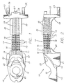
- Fig. 1 illustrates a composite handle 10 designed for attachment to the housing of a conventional electric steam iron.
- the handle 10 has a molded rigid plastic substrate 11 having generally-exposed front and rear surface portions 12 and 13, respectively, connected by a generally-recessed skeletal structure 14.
- the front surface portion 12 of the steam iron handle 10 is molded with a recess 22 adapted to receive a temperature control wheel and containing a hole 25 adapted to receive a screw for attaching the handle to the housing of the iron.
- portion 12 is molded with openings 23 and 24 to accommodate activation buttons for a steam surge and for a water spray, respectively.
- the connecting structure 14 has a +-shaped horizontal backbone comprising a continuous vertically-wide rib 15 and a continuous horizontally-wide rib 16 and a plurality of closely-spaced fin members 17 integrally molded with the ribs 15 and 16 to provide a handle substrate 14 which is relatively light in weight, due to the plurality of air spaces or slots 18 between the fins 17, and yet has excellent strength in all directions.
- the rear surface portion 13 of the rigid substrate 11, in the illustrated embodiment, is molded with a lower central extension flange 26 provided with a hole 27 for receiving an attachment screw to secure the handle to the housing of the iron, and with an opposed pair of internally-threaded bosses 28 and 29 to receive rear cover attachment screws.
- the composite handle 10 of Figs. 1 and 2 also comprise a molded foam resin outer layer 20 which is injection molded over the rigid plastic substrate 11 into the recessed, wrap-around areas 19 thereof, corresponding to the area of the handle which is to be gripped by the user, including the thumb rest areas 21.
- This is accomplished by using the rigid plastic substrate 11 as a mold core, supported within mold halves which provide a wrap around injection cavity corresponding to the recessed areas of the substrate which are to be filled with the foam resin layer 20.
- the injection cavity is then filled at low pressure with a flowable foam-forming resinous composition which contains or generates a blowing agent, such as carbon dioxide gas, and cures to form the compressible, wrap-around, smooth surface foam resin outer layer 20, including the thumb grip areas 21.
- a blowing agent such as carbon dioxide gas
- the composite handle 10 is substantially ready for attachment to the electric steam iron upon removal from the mold upon full cure.
- the smooth outer surface of the foam resin layer 20 has a molded curvature which conforms to the grip of the user and which tapers or transitions to the outer surfaces of the front and rear areas 12 and 13 of the rigid support substrate 11 with which foam layer 20 interfaces for a smooth feel and appearance.
- the rigid plastic substrate 11 illustrated by the drawings is a preferred substrate in that it permits the foam layer to expand partially into the plurality of wrap-around slots 18 of the substrate 11 during the foam-forming expansion and formation of the foam layer 20, to produce wrap-around integration and bonding. Moreover, the compressibility and feel of the foam layer 20 to the grip of the user is uniform since the soft foam layer can be compressed into the wrap-around slots to provide uniform temporary "give" in all radial directions, the foam layer 20 returning to its molded shape when hand pressure is relaxed.
- the present comfort grip handle 10 may be made from two different thermoplastic resins, in a two step standard injection molding process.
- the first step of the manufacturing process is to injection-mold the rigid substrate 11 from a high impact strength resin such as a polycarbonate resin, processed at the recommended molding conditions. After the substrate 11 is molded, it is allowed to cure to room temperature to obtain all the mechanical properties of the molded polycarbonate resin.
- a high impact strength resin such as a polycarbonate resin
- the second step of the process involves injection-molding the overmold foam layer 20 over and around the polycarbonate substrate 11 by first inserting and supporting the substrate 11 centered within the injection mold.
- a preferred overmold material (a melt processible rubber) is a halogenated ethylene interpolymer elastomer with a Durometer of 60 Shore A. The halogenated ethylene interpolymer elastomer is mixed with an endothermic chemical foaming agent composition before being fed into the screw of the injection molding machine.
- a preferred foaming composition consists of a blend of sodium salts of carbonic and polycarboxylic acids together with a styrene-ethylene/butylene-styrene block copolymer, polyalphamethylstyrene blend commerically-available under the trademark Safoam FP-40.
- the foaming agent produces a smooth solid skin around a fine cellular core layer within the halogenated ethylene interpolymer elastomer. This creates the desired cushion feel in the comfort handle.
- a chemical and physical or mechanical bond is formed between the halogenated ethylene interpolymer blend and the polycarbonate substrate during the injection cycle because the resins are compatible and similar in chemical nature.
- the halogenated ethylene polymer blend enters the mold and contacts the polycarbonate substrate, it momentarily melts the surface skin of the polycarbonate and forms a chemical bond.
- the foaming agent begins to activate and decompose over the temperature range 165.56°C to 204.44°C (330°F to 400°F).
- the melt processible foam-forming layer 20 is injection molded at 176.67°C (350°F).
- the foaming agent begins activation in the screw of the injection molding machine. It continues decomposition throughout the remainder of the injection molding cycle and reaches completion before the molding cycle is completed. For the foaming agent to work properly, only about 90% of the injection mold cavity is filled with the foam-forming composite.
- the foaming agent expands and creates a fine cellular structure of the halogenated ethylene interpolymer blend to fill the remainder of the mold cavity.
- the overmold material does not completely fill the inside of the substrate because the foaming agent does not create enough pressure to force the halogenated ethylene polymer down to fill the slots 18 between the ribs 17 in the substrate 11.
- the rigid plastic substrate 11 of the drawings may be provided with slotted, undercut, dovetailed or other integration areas at the recess interfaces between the foam layer 20 and the exposed front and rear surface areas 12 and 13, respectively, of the rigid substrate and/or beneath and adjacent the thumb rest areas 21.
- Such integration areas provide an additional peripheral manual interlock between the foam layer 20 and the substrate 11 to preclude any relative movement therebetween over the lifespan of the appliance.
- the rigid plastic substrate may have a structure different from that illustrated by the present drawings.
- the recessed area of the rigid substrate may be a hollow tubular section, preferably provided with spaced surface holes or openings to admit some of the foam-forming composition and provide anchoring points for the formed foam layer.
- the present handle substrates 11 preferably are injection molded from high impact strength, thermally-stable resinous molding compositions conventionally used for this purpose.
- Preferred thermoplastic resins are polycarbonates, including blends and acrylonitrile-butadiene-styrene (ABS) polymers.
- the foamable resin is one which is chemically-compatible with the resin of the substrate, and the foam-forming reaction is endothermic to avoid excessive heating and softening of the substrate 11.
- a preferred foam-forming composition is a halogenated ethylene interpolymer elastomer composition incorporating a Safoam FP-40 polymer blend-carboxylic acid salt blowing agent composition which generates carbon dioxide during its slow, low pressure expansion step.
- a preferred halogenated ethylene interpolymer elastomer composition is commercially-available from duPont under the trademark "Alcryn”.
- compositions which produce an integral skin, a cellular core and a high strength-to-weight ratio are also suitable.
- Such compositions are commonly based upon thermoplastic elastomeric polymers such as vinyl polymers, polyurethane resins and olefinic polymers and copolymers.
- the present specification refers to the outer surface of the foam layer 20 as being integral and smooth, this means that the layer 20 has a continuous outer skin, devoid of open cells, and formed before expansion is completed. If desired, the outer surface of such skin may be molded to have a textured or patterned feel and appearance, imparted by the surface of the mold.
Landscapes
- Engineering & Computer Science (AREA)
- Textile Engineering (AREA)
- Injection Moulding Of Plastics Or The Like (AREA)
- Manufacture Of Porous Articles, And Recovery And Treatment Of Waste Products (AREA)
Description
- The present invention relates to improving the comfort and feel of handles of devices such as appliances, most particularly electric steam irons and similar devices which are gripped and guided by the hand of the user, sometimes for prolonged periods of time.
- It is known to provide the handles of appliances, such as electric irons, with covers of foam rubber or sponge rubber to cushion the grip and/or for other purposes, and reference is made to US Patents 2,324,226 (Murphy) and 2,639,521 (Rickettson).
- The Murphy Patent 2,324,226 relates to sponge-like rubber covers, such as sleeves, which are forced over the handle of a flatiron as a cushion grip. Such covers are unsatisfactory because they must be produced, separately from the iron, must be applied to the handle of the iron, and can become separated, damaged or lost.
- Rickettson Patent 2,639,521 discloses a sponge rubber or foam rubber pad which is formed separately from the handle of an iron, and then adhered to the handle, such as by rubber cement, to facilitate use of the iron. As with the Murphy Patent, the foam pads of Rickettson must be produced, separate from the iron, and then must be adhered to the handle in a predetermined manner.
- US Patent 4,837,892 (Lo) discloses cushioned handle for appliances such as electric hair curling irons, comprising rigid molded plastic handle halves over which rubber or elastomer overlay surface portions are molded to form composite molded handle halves which are then applied to the appliance and connected to each other by means of penetrating forward and rear screw joiners. The rubber overlay portions are secured to the rigid plastic handle halves by penetration of the rubber into openings or holes in the handle halves during the step or molding the overlay portions over the handle halves. However, this process has serious disadvantages in that the handle halves must be individually molded, then the composite rubber overlay/handle halves must be individually molded, and then the composite handle halves must be applied to the appliance and united by penetrating screw joiners.
- Furthermore, British Patent No. GB 2 274 615 is considered to disclose a process for producing a composite handle for appliance according to the preamble of
claim 1. - The present invention relates to an improved process for producing integral, composite handles having cushioned comfort grips, for appliances, such as electric steam irons.
- According to the present invention there is provided a process producing a composite handle (10) for an appliance, which is strong, light in weight and has a compressible wrap-around grip portion which is comfortable to the hand of the user, comprising the steps of: (a) providing a lightweight, rigid handle substrate (11) having a wrap-around section (14) in a gripping area of the handle intended to be enclosed within the hand of the user; (b) inserting said substrate (11) into an injection mold as a core surrounded by a mold cavity enclosing said gripping area of the substrate; (c) injecting a resinous molding composition into said mold cavity and curing to form a compressible wrap-around layer (20) of resinous composition surrounding and bonded to the gripping area of the rigid handle substrate (11); (d) removing the composite handle (10) from the injection mold; whereby the handle substrate (11) has a gripping area comprising a substantially recessed skeletal structure (14); characterised in that the resinous molding composition is a foam-forming resinous molding composition which forms a layer (20) of resinous foam and in that the substantially recessed skeletal structure (14) comprises a continuous vertically-wide rib and a continuous horizontally-wide rib (15,16) integral with a plurality of closely-spaced vertical fin members (17), whereby the foam-forming resinous molding composition injected in step (c) above expands partially into the spaces (18) between the fin members (17) to improve the bond between the rigid substrate (11) and the layer (20) of resinous foam.
- The composite handle is completely formed by the present two-step process, ready for attachment to the predetermined appliance in conventional manner.
- According to a further aspect of the present invention there is provided a composite handle (10) for an appliance, which is strong, light in weight, and comfortable to the hand of the user, comprising a rigid handle substrate (11) molded of resinous composition, and having exposed surface areas (12,13) adjacent a recessed wrap-around gripping area (14), and having molded into said recessed gripping area (14) a continuous wrap-around layer (20) of compressible resinous composition which is bonded to the substrate (11) to provide a comfort grip for the appliance, whereby the recessed gripping area (14) of the rigid substrate (11) comprises a substantially recessed skeletal structure (14); characterised in that the resinous composition comprises resinous foam and in that the substantially recessed skeletal structure (14) comprises a continuous vertically-wide rib and a continuous horizontally-wide rib (15,16) integral with a plurality of closely-spaced vertical fin members (17), said layer (20) of resinous foam being expanded to some extent into the spaces (18) between said vertical fin members (17) to bond the foam layer (20) to the substrate (11).
- In the accompanying drawings:
- Fig. 1 is a top view, in partial section, illustrating a handle for a steam iron, with portions of the rigid plastic handle substrate in the recessed wrap-around gripping areas being shown in broken lines where overlaid by the foam resin cushion grip, and with other portions of the rigid plastic handle substrate being exposed by removal of the foam resin cushion grip, and
- Fig. 2 is a side view of the composite iron handle of Fig. 1.
-
- Fig. 1 illustrates a
composite handle 10 designed for attachment to the housing of a conventional electric steam iron. Thehandle 10 has a molded rigidplastic substrate 11 having generally-exposed front andrear surface portions skeletal structure 14. In the embodiment illustrated, thefront surface portion 12 of thesteam iron handle 10 is molded with arecess 22 adapted to receive a temperature control wheel and containing ahole 25 adapted to receive a screw for attaching the handle to the housing of the iron. Also,portion 12 is molded withopenings structure 14 has a +-shaped horizontal backbone comprising a continuous vertically-wide rib 15 and a continuous horizontally-wide rib 16 and a plurality of closely-spacedfin members 17 integrally molded with theribs handle substrate 14 which is relatively light in weight, due to the plurality of air spaces orslots 18 between thefins 17, and yet has excellent strength in all directions. - The
rear surface portion 13 of therigid substrate 11, in the illustrated embodiment, is molded with a lowercentral extension flange 26 provided with ahole 27 for receiving an attachment screw to secure the handle to the housing of the iron, and with an opposed pair of internally-threadedbosses - The
composite handle 10 of Figs. 1 and 2 also comprise a molded foam resinouter layer 20 which is injection molded over the rigidplastic substrate 11 into the recessed, wrap-aroundareas 19 thereof, corresponding to the area of the handle which is to be gripped by the user, including thethumb rest areas 21. This is accomplished by using the rigidplastic substrate 11 as a mold core, supported within mold halves which provide a wrap around injection cavity corresponding to the recessed areas of the substrate which are to be filled with thefoam resin layer 20. The injection cavity is then filled at low pressure with a flowable foam-forming resinous composition which contains or generates a blowing agent, such as carbon dioxide gas, and cures to form the compressible, wrap-around, smooth surface foam resinouter layer 20, including thethumb grip areas 21. Thecomposite handle 10 is substantially ready for attachment to the electric steam iron upon removal from the mold upon full cure. The smooth outer surface of thefoam resin layer 20 has a molded curvature which conforms to the grip of the user and which tapers or transitions to the outer surfaces of the front andrear areas rigid support substrate 11 with whichfoam layer 20 interfaces for a smooth feel and appearance. - The rigid
plastic substrate 11 illustrated by the drawings is a preferred substrate in that it permits the foam layer to expand partially into the plurality of wrap-aroundslots 18 of thesubstrate 11 during the foam-forming expansion and formation of thefoam layer 20, to produce wrap-around integration and bonding. Moreover, the compressibility and feel of thefoam layer 20 to the grip of the user is uniform since the soft foam layer can be compressed into the wrap-around slots to provide uniform temporary "give" in all radial directions, thefoam layer 20 returning to its molded shape when hand pressure is relaxed. - The present
comfort grip handle 10 may be made from two different thermoplastic resins, in a two step standard injection molding process. - The first step of the manufacturing process is to injection-mold the
rigid substrate 11 from a high impact strength resin such as a polycarbonate resin, processed at the recommended molding conditions. After thesubstrate 11 is molded, it is allowed to cure to room temperature to obtain all the mechanical properties of the molded polycarbonate resin. - The second step of the process involves injection-molding the overmold
foam layer 20 over and around thepolycarbonate substrate 11 by first inserting and supporting thesubstrate 11 centered within the injection mold. A preferred overmold material (a melt processible rubber) is a halogenated ethylene interpolymer elastomer with a Durometer of 60 Shore A. The halogenated ethylene interpolymer elastomer is mixed with an endothermic chemical foaming agent composition before being fed into the screw of the injection molding machine. A preferred foaming composition consists of a blend of sodium salts of carbonic and polycarboxylic acids together with a styrene-ethylene/butylene-styrene block copolymer, polyalphamethylstyrene blend commerically-available under the trademark Safoam FP-40. The foaming agent produces a smooth solid skin around a fine cellular core layer within the halogenated ethylene interpolymer elastomer. This creates the desired cushion feel in the comfort handle. - A chemical and physical or mechanical bond is formed between the halogenated ethylene interpolymer blend and the polycarbonate substrate during the injection cycle because the resins are compatible and similar in chemical nature. As the halogenated ethylene polymer blend enters the mold and contacts the polycarbonate substrate, it momentarily melts the surface skin of the polycarbonate and forms a chemical bond.
- The foaming agent begins to activate and decompose over the temperature range 165.56°C to 204.44°C (330°F to 400°F). The melt processible foam-forming
layer 20 is injection molded at 176.67°C (350°F). The foaming agent begins activation in the screw of the injection molding machine. It continues decomposition throughout the remainder of the injection molding cycle and reaches completion before the molding cycle is completed. For the foaming agent to work properly, only about 90% of the injection mold cavity is filled with the foam-forming composite. The foaming agent expands and creates a fine cellular structure of the halogenated ethylene interpolymer blend to fill the remainder of the mold cavity. The overmold material does not completely fill the inside of the substrate because the foaming agent does not create enough pressure to force the halogenated ethylene polymer down to fill theslots 18 between theribs 17 in thesubstrate 11. Once the molding cycle is completed, the finished handle is removed from the mold and allowed to fully cure. - The rigid
plastic substrate 11 of the drawings may be provided with slotted, undercut, dovetailed or other integration areas at the recess interfaces between thefoam layer 20 and the exposed front andrear surface areas thumb rest areas 21. Such integration areas provide an additional peripheral manual interlock between thefoam layer 20 and thesubstrate 11 to preclude any relative movement therebetween over the lifespan of the appliance. - The rigid plastic substrate may have a structure different from that illustrated by the present drawings. For example, the recessed area of the rigid substrate may be a hollow tubular section, preferably provided with spaced surface holes or openings to admit some of the foam-forming composition and provide anchoring points for the formed foam layer.
- It will be apparent to those skilled in the art that the
present handle substrates 11 preferably are injection molded from high impact strength, thermally-stable resinous molding compositions conventionally used for this purpose. Preferred thermoplastic resins are polycarbonates, including blends and acrylonitrile-butadiene-styrene (ABS) polymers. - It will also be apparent to those skilled in the art that a variety of low durometer foam-forming thermoplastic resinous compositions are suitable for use as injection molding compositions to form the present
compressible foam layer 20. Preferably the foamable resin is one which is chemically-compatible with the resin of the substrate, and the foam-forming reaction is endothermic to avoid excessive heating and softening of thesubstrate 11. - A preferred foam-forming composition is a halogenated ethylene interpolymer elastomer composition incorporating a Safoam FP-40 polymer blend-carboxylic acid salt blowing agent composition which generates carbon dioxide during its slow, low pressure expansion step. A preferred halogenated ethylene interpolymer elastomer composition is commercially-available from duPont under the trademark "Alcryn".
- Other conventional foam-forming compositions which produce an integral skin, a cellular core and a high strength-to-weight ratio are also suitable. Such compositions are commonly based upon thermoplastic elastomeric polymers such as vinyl polymers, polyurethane resins and olefinic polymers and copolymers.
- The present specification refers to the outer surface of the
foam layer 20 as being integral and smooth, this means that thelayer 20 has a continuous outer skin, devoid of open cells, and formed before expansion is completed. If desired, the outer surface of such skin may be molded to have a textured or patterned feel and appearance, imparted by the surface of the mold.
Claims (12)
- A process producing a composite handle (10) for an appliance, which is strong, light in weight and has a compressible wrap-around grip portion which is comfortable to the hand of the user, comprising the steps of:whereby the handle substrate (11) has a gripping area comprising a substantially recessed skeletal structure (14);(a) providing a lightweight, rigid handle substrate (11) having a wrap-around section (14) in a gripping area of the handle intended to be enclosed within the hand of the user;(b) inserting said substrate (11) into an injection mold as a core surrounded by a mold cavity enclosing said gripping area of the substrate;(c) injecting a resinous molding composition into said mold cavity and curing to form a compressible wrap-around layer (20) of resinous composition surrounding and bonded to the gripping area of the rigid handle substrate (11);(d) removing the composite handle (10) from the injection mold;
characterised in that the resinous molding composition is a foam-forming resinous molding composition which forms a layer (20) of resinous foam and in that the substantially recessed skeletal structure (14) comprises a continuous vertically-wide rib and a continuous horizontally-wide rib (15,16) integral with a plurality of closely-spaced vertical fin members (17), whereby the foam-forming resinous molding composition injected in step (c) above expands partially into the spaces (18) between the fin members (17) to improve the bond between the rigid substrate (11) and the layer (20) of resinous foam. - A process according to claim 1 in which the wrap-around section (14) of the handle substrate (11) comprises a recessed gripping area.
- A process according to either one of claims 1 or 2 in which the composite handle (10) comprises rigid outer surface portions (12,13) adjacent said wrap-around gripping area (14).
- A process according to any one of the preceding claims comprising injection molding said rigid handle substrate (11) in step (a).
- A process according to claim 4 comprising injection-molding the handle substrate (11) from a high impact strength, thermally-stable resinous molding composition.
- A process according to claim 5 in which the resinous molding composition (20) comprises a polycarbonate resin or an acrylonitrile-butadiene-styrene polymer.
- A process according to any one of the preceding claims in which the foam-forming resinous composition (20) of step (c) comprises a synthetic thermoplastic elastomeric polymer.
- A composite handle (10) for an appliance, which is strong, light in weight, and comfortable to the hand of the user, comprising a rigid handle substrate (11) molded of resinous composition, and having exposed surface areas (12,13) adjacent a recessed wrap-around gripping area (14), and having molded into said recessed gripping area (14) a continuous wrap-around layer (20) of compressible resinous composition which is bonded to the substrate (11) to provide a comfort grip for the appliance, whereby the recessed gripping area (14) of the rigid substrate (11) comprises a substantially recessed skeletal structure (14);
characterised in that the resinous composition comprises resinous foam and in that the substantially recessed skeletal structure (14) comprises a continuous vertically-wide rib and a continuous horizontally-wide rib (15,16) integral with a plurality of closely-spaced vertical fin members (17), said layer (20) of resinous foam being expanded to some extent into the spaces (18) between said vertical fin members (17) to bond the foam layer (20) to the substrate (11). - A composite handle (10) as claimed in claim 8 in which the substrate (11) is molded of a high impact strength, thermally stable resinous composition.
- A composite handle (10) according to either one of claims 8 or 9 in which the rigid substrate (11) comprises a polycarbonate resin.
- A composite handle (10) according to either one of claims 8 or 9 in which the rigid substrate (11) comprises an acrylonitrile-butadiene-styrene.
- A composite handle (10) according to any one of claims 8 to 11 in which the resinous foam (20) comprises a synthetic thermoplastic elastomer.
Applications Claiming Priority (2)
| Application Number | Priority Date | Filing Date | Title |
|---|---|---|---|
| US08/781,394 US5862571A (en) | 1997-01-10 | 1997-01-10 | Comfort grip handle and process |
| US781394 | 2004-02-18 |
Publications (3)
| Publication Number | Publication Date |
|---|---|
| EP0857812A2 EP0857812A2 (en) | 1998-08-12 |
| EP0857812A3 EP0857812A3 (en) | 1999-01-13 |
| EP0857812B1 true EP0857812B1 (en) | 2002-09-11 |
Family
ID=25122585
Family Applications (1)
| Application Number | Title | Priority Date | Filing Date |
|---|---|---|---|
| EP97310602A Expired - Lifetime EP0857812B1 (en) | 1997-01-10 | 1997-12-24 | Comfort grip handle and process |
Country Status (6)
| Country | Link |
|---|---|
| US (2) | US5862571A (en) |
| EP (1) | EP0857812B1 (en) |
| BR (1) | BR9800168A (en) |
| CA (1) | CA2225673A1 (en) |
| DE (1) | DE69715366T2 (en) |
| ES (1) | ES2178742T3 (en) |
Families Citing this family (31)
| Publication number | Priority date | Publication date | Assignee | Title |
|---|---|---|---|---|
| US5781958A (en) * | 1996-02-14 | 1998-07-21 | Gillette Canada Inc. | Brush handle |
| US6070329A (en) * | 1997-06-30 | 2000-06-06 | Camillus Cutlery Co. | Knife and handle construction and method of fabricating such knives |
| US6308378B1 (en) | 1999-06-01 | 2001-10-30 | Porter-Cable Corporation | Frictional gripping arrangement for a power tool handle |
| WO2001064419A1 (en) * | 2000-02-29 | 2001-09-07 | Bemis Manufacturing Company | Co-injection apparatus for injection molding |
| US6964748B2 (en) | 2000-11-30 | 2005-11-15 | Bemis Manufacturing Company | Co-injection methods using endothermic-blowing agents and products made therefrom |
| US20030172498A1 (en) * | 2002-03-15 | 2003-09-18 | Polzin Bruce C. | Apparatus to cushion and dampen vibration and method |
| US6796389B2 (en) | 2002-03-28 | 2004-09-28 | Snap-On Incorporated | Power hand tool and removable grip therefor |
| KR100469696B1 (en) * | 2002-06-10 | 2005-02-02 | 엘지전자 주식회사 | Plasma display panel |
| US7635114B2 (en) * | 2002-06-18 | 2009-12-22 | Mfs, Llc | Rotationally molded, reinforced decorative fence post and method of making same |
| US20050129921A1 (en) * | 2003-12-12 | 2005-06-16 | Laws R. D. | Molded article with foam-encased reinforcing member |
| US20050129901A1 (en) * | 2003-12-12 | 2005-06-16 | Mity-Lite, Inc. | Molded article with adhesion-resistant reinforcing member and method |
| USD495198S1 (en) | 2002-12-27 | 2004-08-31 | Virutex Ilko S.A. | Handle |
| US20040147346A1 (en) * | 2003-01-24 | 2004-07-29 | Casasanta Joseph G. | Grip for a hockey stick with a hollow-ended shaft |
| US7377859B2 (en) * | 2003-05-05 | 2008-05-27 | Underscore Golf Llc | Decorative grip and method for making |
| US7770262B2 (en) * | 2003-05-19 | 2010-08-10 | Robert Bosch Tool Corporation | Cushion grip handle |
| TWI273019B (en) * | 2003-07-25 | 2007-02-11 | Hon Hai Prec Ind Co Ltd | A method of transfer pattern |
| ATE499860T1 (en) * | 2003-11-18 | 2011-03-15 | Trisa Holding Ag | TOOTHBRUSH BODY |
| US20070275229A1 (en) * | 2003-12-12 | 2007-11-29 | Laws R D | Molded article with foam-encased adhesion-resistant reinforcing member and method |
| US7273571B2 (en) * | 2004-02-25 | 2007-09-25 | Mfs, Llc | Molded table and its method of manufacture |
| US20050197219A1 (en) * | 2004-03-08 | 2005-09-08 | Casasanta Joseph G.Jr. | System and method for making a customized cushioned grip on a handle |
| US20050250605A1 (en) * | 2004-05-07 | 2005-11-10 | Tubular Fabricators Industry, Inc. | Replaceable grip handle |
| US7861380B2 (en) * | 2004-05-07 | 2011-01-04 | Tubular Fabricators Industry, Inc. | Replaceable hand grip |
| US8927083B2 (en) * | 2009-01-19 | 2015-01-06 | Mack Molding Company | Handle and method of fabricating a handle for a medical device |
| US8307769B1 (en) | 2009-07-31 | 2012-11-13 | Mity-Lite, Inc. | Plastic and plywood laminate table with drop corner |
| US8550012B2 (en) | 2011-10-27 | 2013-10-08 | Mity-Lite, Inc. | Leg locking and folding mechanism for folding table |
| US8671850B2 (en) | 2011-10-27 | 2014-03-18 | Mity-Lite, Inc. | Convertible tabletop with pivotal modesty panel |
| FR3026288B1 (en) * | 2014-09-30 | 2017-02-24 | Seb Sa | HANDLE COMPRISING A THERMOELECTRIC GENERATOR |
| DE102015100076A1 (en) | 2015-01-07 | 2016-07-07 | Miele & Cie. Kg | Handle element for an iron, iron and method for producing an iron |
| US20160279842A1 (en) * | 2015-03-23 | 2016-09-29 | Yao-Lin Cho | Manufacturing stesp for hand tool |
| TWI731527B (en) * | 2019-12-25 | 2021-06-21 | 緯創資通股份有限公司 | Electronic device |
| EP3912512B1 (en) | 2020-05-20 | 2026-04-01 | Trisa Holding AG | Hygiene product, in particular oral hygiene product |
Family Cites Families (50)
| Publication number | Priority date | Publication date | Assignee | Title |
|---|---|---|---|---|
| US20165A (en) * | 1858-05-04 | Improvement in punching metallic tubes | ||
| US34194A (en) * | 1862-01-21 | Improvement in road-scrapers | ||
| USRE20165E (en) * | 1936-11-10 | Iron handle | ||
| DE7815717U1 (en) * | 1979-12-20 | Dokoupil, Jiri, Dipl.-Ing., 6251 Gueckingen | Industrial steam iron | |
| US1455502A (en) * | 1922-01-16 | 1923-05-15 | Lewis H Mertz | Implement handle |
| US1536288A (en) * | 1922-12-26 | 1925-05-05 | Rubber Dev Company | Method of manufacture of rubber compound |
| US1908834A (en) * | 1927-12-29 | 1933-05-16 | Electrolux Corp | Handle |
| US1940755A (en) * | 1931-05-06 | 1933-12-26 | Knapp Monarch Co | Iron handle |
| US1958668A (en) * | 1933-12-12 | 1934-05-15 | Alexander T Lark | Electric iron handle |
| US2144474A (en) * | 1936-09-23 | 1939-01-17 | Westinghouse Electric & Mfg Co | Ventilated handle for sadirons |
| US2121989A (en) * | 1937-12-01 | 1938-06-28 | Robert M Hawk | Combined handle grip and weapon |
| US2140157A (en) * | 1938-03-21 | 1938-12-13 | Knapp Monarch Co | Handle |
| US2290336A (en) * | 1940-05-03 | 1942-07-21 | James B Kirby | Handle construction |
| US2324226A (en) * | 1941-07-05 | 1943-07-13 | Bernard J Murphy | Hand grip for electric irons |
| US2466719A (en) * | 1946-11-26 | 1949-04-12 | James C Mackearnin | Handle pad |
| US2639521A (en) * | 1951-02-23 | 1953-05-26 | Rickettson Margaret | Handle member |
| US3122774A (en) * | 1961-08-08 | 1964-03-03 | Lamb Thomas | Handles |
| US3321798A (en) * | 1965-05-18 | 1967-05-30 | Jacques A Plamondon | Handle for lunch boxes |
| US3584366A (en) * | 1968-08-07 | 1971-06-15 | Wallace Expanding Machines | Process for manufacture of shadow mask frames |
| US3762453A (en) * | 1971-05-12 | 1973-10-02 | Stanley Works | Hand tool handle |
| AT335957B (en) * | 1971-08-27 | 1977-04-12 | Rowenta Werke Gmbh | IRON WITH A HANDLE |
| US3813729A (en) * | 1973-01-04 | 1974-06-04 | M Szabo | Rigid substantially u-shaped handle with closed-cell foam handgrip |
| DE2810418C3 (en) * | 1978-03-10 | 1980-09-11 | Gerhard Alarich 5650 Solingen Ern | Double-shell tool handle, especially for knife, saw, or the like |
| DE8513768U1 (en) * | 1985-05-09 | 1985-08-01 | Weigl, Robert, 8027 Neuried | Grip sleeve for iron |
| DE3603409A1 (en) * | 1985-06-05 | 1986-12-11 | Rowenta-Werke Gmbh, 6050 Offenbach | ELECTRICALLY HEATED STEAM IRON |
| DE3622596A1 (en) * | 1985-07-08 | 1987-01-15 | Heinz Rauh | Handle made of thermoplastic |
| IT208610Z2 (en) * | 1986-03-21 | 1988-05-28 | Macpi Spa | INDUSTRIAL-TYPE IRON HANDLE, PROVIDED WITH A PARTICULAR SHAPING AND SURFACE FINISHING, SUITABLE FOR FAVORING IT AND MAKING IT MORE COMFORTABLE TO TAKE, BY THE OPERATOR. |
| USD294991S (en) | 1986-06-26 | 1988-03-29 | Wearever-Proctorsilex | Steam iron |
| FR2606043B1 (en) * | 1986-10-31 | 1988-12-30 | Seb Sa | STEAM IRON |
| US5097566A (en) * | 1987-10-07 | 1992-03-24 | Bettcher Industries, Inc. | Slip-resistant cushioning covers for handles |
| US4837892A (en) * | 1988-03-04 | 1989-06-13 | Conair Corporation | Cushioned handle structure for personal care appliances |
| US5134008A (en) * | 1988-04-07 | 1992-07-28 | Scanalma Ab | Covers for handles and the like |
| US4953862A (en) * | 1989-04-18 | 1990-09-04 | Uke Alan K | Hand grip for sporting equipment or tools |
| US4964192A (en) * | 1989-04-24 | 1990-10-23 | Marui, Ltd. | Multiple radius grip |
| USRE34194E (en) * | 1990-03-26 | 1993-03-16 | Oxo International L.P. | Universal handle for hand-held implement |
| DE4038598C1 (en) * | 1990-12-04 | 1991-11-28 | Klaus 7312 Kirchheim De Lenhart | |
| US5375486A (en) * | 1991-06-10 | 1994-12-27 | Carmien; Joseph A. | Surface protective striking tools |
| US5261665A (en) * | 1992-02-11 | 1993-11-16 | Robert A. Paley, Inc. | Golf club grip formed of a plurality of materials and method of manufacture thereof |
| FR2687416B1 (en) * | 1992-02-17 | 1994-09-02 | Moulinex Sa | IRON SOLE AND MANUFACTURING METHOD THEREOF. |
| GB2274515B (en) * | 1993-01-22 | 1996-04-24 | British Gas Plc | Surface level checking apparatus |
| GB2274615A (en) * | 1993-01-29 | 1994-08-03 | Moss Prod Pty Ltd | Moulded plastic handle and method of its manufacture |
| DE4411790A1 (en) * | 1994-04-06 | 1995-10-12 | Braun Ag | Electric iron |
| EP0676498A3 (en) * | 1994-04-06 | 1996-04-17 | Braun Ag | Outlet and distribution of steam. |
| FR2718467B1 (en) * | 1994-04-08 | 1996-11-29 | Moulinex Sa | Iron with an attached sole. |
| DE4422090A1 (en) * | 1994-06-24 | 1996-01-11 | Braun Ag | Edge shape on an iron |
| DE4422089C2 (en) * | 1994-06-24 | 1999-12-09 | Braun Gmbh | Method for producing an iron, and an iron produced using the method |
| IT1268346B1 (en) * | 1994-11-18 | 1997-02-27 | Ariete Srl | METHOD FOR THE MANUFACTURE OF IRON WITH STEEL INSOLE |
| DE19508446A1 (en) * | 1995-03-09 | 1996-09-12 | Braun Ag | Iron |
| US5551323A (en) * | 1995-03-22 | 1996-09-03 | Beere Precision Medical Instruments, Inc. | Screwdriver handle |
| DE19539200C2 (en) * | 1995-10-20 | 1998-12-24 | Holland Letz Felo Werkzeug | Tool handle, especially for screwdrivers |
-
1997
- 1997-01-10 US US08/781,394 patent/US5862571A/en not_active Expired - Fee Related
- 1997-12-22 CA CA002225673A patent/CA2225673A1/en not_active Abandoned
- 1997-12-24 DE DE69715366T patent/DE69715366T2/en not_active Expired - Lifetime
- 1997-12-24 ES ES97310602T patent/ES2178742T3/en not_active Expired - Lifetime
- 1997-12-24 EP EP97310602A patent/EP0857812B1/en not_active Expired - Lifetime
-
1998
- 1998-01-09 BR BR9800168A patent/BR9800168A/en not_active IP Right Cessation
- 1998-11-17 US US09/195,310 patent/US6024903A/en not_active Expired - Fee Related
Also Published As
| Publication number | Publication date |
|---|---|
| BR9800168A (en) | 1999-03-23 |
| EP0857812A3 (en) | 1999-01-13 |
| CA2225673A1 (en) | 1998-07-10 |
| DE69715366T2 (en) | 2003-07-31 |
| DE69715366D1 (en) | 2002-10-17 |
| US6024903A (en) | 2000-02-15 |
| EP0857812A2 (en) | 1998-08-12 |
| US5862571A (en) | 1999-01-26 |
| ES2178742T3 (en) | 2003-01-01 |
Similar Documents
| Publication | Publication Date | Title |
|---|---|---|
| US6024903A (en) | Process for making a comfort grip handle | |
| CA1223911A (en) | Molded foam-backed carpet assembly and method of producing same | |
| US20030172498A1 (en) | Apparatus to cushion and dampen vibration and method | |
| US20030070259A1 (en) | Elastomeric grips for personal care products | |
| WO2005082581A1 (en) | Separable apparatus to cushion and dampen vibration and method | |
| TWI814833B (en) | Mold for a support element, for example a saddle for vehicles, and support element obtainable with such a mold | |
| KR20120135096A (en) | Flexible implement handle grip and method of making same | |
| WO1995035208A1 (en) | Laminated body and method of manufacturing the same | |
| JP2002541955A (en) | toothbrush | |
| ITTO980257A1 (en) | INJECTION EXPANDED PRODUCT AND PROCEDURE FOR ITS MANUFACTURE. | |
| JPH0211482A (en) | Water resistant sheet for snow and water vehicle and manufacture thereof | |
| JPH1157090A (en) | Golf club grip | |
| JPH02171362A (en) | Air bag storage cover | |
| MXPA98000286A (en) | Handle of comfort grip and procedimie | |
| JP4696366B2 (en) | Thermoplastic resin foam molding | |
| JPS61246056A (en) | Resin molded shape having soft skin and manufacture thereof | |
| KR100198189B1 (en) | A process for preparing a sole using a polyurethane film and the sole by the process | |
| JP3805423B2 (en) | Injection molding method for resin molded product having partial decoration | |
| JPH0890688A (en) | Synthetic resin vessel or the like and manufacture thereof | |
| JPS58110225A (en) | Manufacture of saddle for motor cycle | |
| US20080313852A1 (en) | Part Which can be Gripped Manually and Process for Production Thereof | |
| KR920010270B1 (en) | Manufacturing method of in sole use high elastic polyurethane | |
| KR200359535Y1 (en) | manufacturing mould for the shoe-sole which has different colors | |
| JPH06320656A (en) | Fiber-reinforced thermoplastic resin molding and method for producing the same | |
| CA1078572A (en) | Injection molding process |
Legal Events
| Date | Code | Title | Description |
|---|---|---|---|
| PUAI | Public reference made under article 153(3) epc to a published international application that has entered the european phase |
Free format text: ORIGINAL CODE: 0009012 |
|
| AK | Designated contracting states |
Kind code of ref document: A2 Designated state(s): DE ES FR GB GR IT NL |
|
| AX | Request for extension of the european patent |
Free format text: AL;LT;LV;MK;RO;SI |
|
| PUAL | Search report despatched |
Free format text: ORIGINAL CODE: 0009013 |
|
| AK | Designated contracting states |
Kind code of ref document: A3 Designated state(s): AT BE CH DE DK ES FI FR GB GR IE IT LI LU MC NL PT SE |
|
| AX | Request for extension of the european patent |
Free format text: AL;LT;LV;MK;RO;SI |
|
| 17P | Request for examination filed |
Effective date: 19990219 |
|
| AKX | Designation fees paid |
Free format text: DE ES FR GB GR IT NL |
|
| 17Q | First examination report despatched |
Effective date: 20000406 |
|
| GRAG | Despatch of communication of intention to grant |
Free format text: ORIGINAL CODE: EPIDOS AGRA |
|
| GRAG | Despatch of communication of intention to grant |
Free format text: ORIGINAL CODE: EPIDOS AGRA |
|
| GRAH | Despatch of communication of intention to grant a patent |
Free format text: ORIGINAL CODE: EPIDOS IGRA |
|
| GRAH | Despatch of communication of intention to grant a patent |
Free format text: ORIGINAL CODE: EPIDOS IGRA |
|
| GRAA | (expected) grant |
Free format text: ORIGINAL CODE: 0009210 |
|
| AK | Designated contracting states |
Kind code of ref document: B1 Designated state(s): DE ES FR GB GR IT NL |
|
| PG25 | Lapsed in a contracting state [announced via postgrant information from national office to epo] |
Ref country code: NL Free format text: LAPSE BECAUSE OF FAILURE TO SUBMIT A TRANSLATION OF THE DESCRIPTION OR TO PAY THE FEE WITHIN THE PRESCRIBED TIME-LIMIT Effective date: 20020911 |
|
| REG | Reference to a national code |
Ref country code: GB Ref legal event code: FG4D |
|
| REF | Corresponds to: |
Ref document number: 69715366 Country of ref document: DE Date of ref document: 20021017 |
|
| REG | Reference to a national code |
Ref country code: ES Ref legal event code: FG2A Ref document number: 2178742 Country of ref document: ES Kind code of ref document: T3 |
|
| REG | Reference to a national code |
Ref country code: GR Ref legal event code: EP Ref document number: 20020404182 Country of ref document: GR |
|
| ET | Fr: translation filed | ||
| NLV1 | Nl: lapsed or annulled due to failure to fulfill the requirements of art. 29p and 29m of the patents act | ||
| PLBE | No opposition filed within time limit |
Free format text: ORIGINAL CODE: 0009261 |
|
| STAA | Information on the status of an ep patent application or granted ep patent |
Free format text: STATUS: NO OPPOSITION FILED WITHIN TIME LIMIT |
|
| 26N | No opposition filed |
Effective date: 20030612 |
|
| PGFP | Annual fee paid to national office [announced via postgrant information from national office to epo] |
Ref country code: GR Payment date: 20041223 Year of fee payment: 8 |
|
| PG25 | Lapsed in a contracting state [announced via postgrant information from national office to epo] |
Ref country code: GR Free format text: LAPSE BECAUSE OF NON-PAYMENT OF DUE FEES Effective date: 20020911 |
|
| PGFP | Annual fee paid to national office [announced via postgrant information from national office to epo] |
Ref country code: IT Payment date: 20101227 Year of fee payment: 14 Ref country code: GB Payment date: 20101229 Year of fee payment: 14 |
|
| PGFP | Annual fee paid to national office [announced via postgrant information from national office to epo] |
Ref country code: ES Payment date: 20111226 Year of fee payment: 15 Ref country code: FR Payment date: 20120104 Year of fee payment: 15 |
|
| PGFP | Annual fee paid to national office [announced via postgrant information from national office to epo] |
Ref country code: DE Payment date: 20111229 Year of fee payment: 15 |
|
| GBPC | Gb: european patent ceased through non-payment of renewal fee |
Effective date: 20121224 |
|
| REG | Reference to a national code |
Ref country code: FR Ref legal event code: ST Effective date: 20130830 |
|
| REG | Reference to a national code |
Ref country code: DE Ref legal event code: R119 Ref document number: 69715366 Country of ref document: DE Effective date: 20130702 |
|
| PG25 | Lapsed in a contracting state [announced via postgrant information from national office to epo] |
Ref country code: DE Free format text: LAPSE BECAUSE OF NON-PAYMENT OF DUE FEES Effective date: 20130702 |
|
| PG25 | Lapsed in a contracting state [announced via postgrant information from national office to epo] |
Ref country code: FR Free format text: LAPSE BECAUSE OF NON-PAYMENT OF DUE FEES Effective date: 20130102 Ref country code: GB Free format text: LAPSE BECAUSE OF NON-PAYMENT OF DUE FEES Effective date: 20121224 |
|
| PG25 | Lapsed in a contracting state [announced via postgrant information from national office to epo] |
Ref country code: IT Free format text: LAPSE BECAUSE OF NON-PAYMENT OF DUE FEES Effective date: 20121224 |
|
| REG | Reference to a national code |
Ref country code: ES Ref legal event code: FD2A Effective date: 20140306 |
|
| PG25 | Lapsed in a contracting state [announced via postgrant information from national office to epo] |
Ref country code: ES Free format text: LAPSE BECAUSE OF NON-PAYMENT OF DUE FEES Effective date: 20121225 |