EP0857660A1 - Closure cap, and method and apparatus for its manufacture - Google Patents
Closure cap, and method and apparatus for its manufacture Download PDFInfo
- Publication number
- EP0857660A1 EP0857660A1 EP97811031A EP97811031A EP0857660A1 EP 0857660 A1 EP0857660 A1 EP 0857660A1 EP 97811031 A EP97811031 A EP 97811031A EP 97811031 A EP97811031 A EP 97811031A EP 0857660 A1 EP0857660 A1 EP 0857660A1
- Authority
- EP
- European Patent Office
- Prior art keywords
- capsule
- embossing
- limiting sleeve
- sealing
- stamp
- Prior art date
- Legal status (The legal status is an assumption and is not a legal conclusion. Google has not performed a legal analysis and makes no representation as to the accuracy of the status listed.)
- Granted
Links
Images


Classifications
-
- B—PERFORMING OPERATIONS; TRANSPORTING
- B65—CONVEYING; PACKING; STORING; HANDLING THIN OR FILAMENTARY MATERIAL
- B65D—CONTAINERS FOR STORAGE OR TRANSPORT OF ARTICLES OR MATERIALS, e.g. BAGS, BARRELS, BOTTLES, BOXES, CANS, CARTONS, CRATES, DRUMS, JARS, TANKS, HOPPERS, FORWARDING CONTAINERS; ACCESSORIES, CLOSURES, OR FITTINGS THEREFOR; PACKAGING ELEMENTS; PACKAGES
- B65D41/00—Caps, e.g. crown caps or crown seals, i.e. members having parts arranged for engagement with the external periphery of a neck or wall defining a pouring opening or discharge aperture; Protective cap-like covers for closure members, e.g. decorative covers of metal foil or paper
- B65D41/02—Caps or cap-like covers without lines of weakness, tearing strips, tags, or like opening or removal devices
- B65D41/04—Threaded or like caps or cap-like covers secured by rotation
- B65D41/0435—Threaded or like caps or cap-like covers secured by rotation with separate sealing elements
- B65D41/045—Discs
-
- B—PERFORMING OPERATIONS; TRANSPORTING
- B29—WORKING OF PLASTICS; WORKING OF SUBSTANCES IN A PLASTIC STATE IN GENERAL
- B29C—SHAPING OR JOINING OF PLASTICS; SHAPING OF MATERIAL IN A PLASTIC STATE, NOT OTHERWISE PROVIDED FOR; AFTER-TREATMENT OF THE SHAPED PRODUCTS, e.g. REPAIRING
- B29C33/00—Moulds or cores; Details thereof or accessories therefor
- B29C33/44—Moulds or cores; Details thereof or accessories therefor with means for, or specially constructed to facilitate, the removal of articles, e.g. of undercut articles
- B29C33/48—Moulds or cores; Details thereof or accessories therefor with means for, or specially constructed to facilitate, the removal of articles, e.g. of undercut articles with means for collapsing or disassembling
- B29C33/485—Moulds or cores; Details thereof or accessories therefor with means for, or specially constructed to facilitate, the removal of articles, e.g. of undercut articles with means for collapsing or disassembling cores or mandrels
-
- B—PERFORMING OPERATIONS; TRANSPORTING
- B29—WORKING OF PLASTICS; WORKING OF SUBSTANCES IN A PLASTIC STATE IN GENERAL
- B29C—SHAPING OR JOINING OF PLASTICS; SHAPING OF MATERIAL IN A PLASTIC STATE, NOT OTHERWISE PROVIDED FOR; AFTER-TREATMENT OF THE SHAPED PRODUCTS, e.g. REPAIRING
- B29C43/00—Compression moulding, i.e. applying external pressure to flow the moulding material; Apparatus therefor
- B29C43/32—Component parts, details or accessories; Auxiliary operations
- B29C43/36—Moulds for making articles of definite length, i.e. discrete articles
- B29C43/361—Moulds for making articles of definite length, i.e. discrete articles with pressing members independently movable of the parts for opening or closing the mould, e.g. movable pistons
-
- B—PERFORMING OPERATIONS; TRANSPORTING
- B29—WORKING OF PLASTICS; WORKING OF SUBSTANCES IN A PLASTIC STATE IN GENERAL
- B29C—SHAPING OR JOINING OF PLASTICS; SHAPING OF MATERIAL IN A PLASTIC STATE, NOT OTHERWISE PROVIDED FOR; AFTER-TREATMENT OF THE SHAPED PRODUCTS, e.g. REPAIRING
- B29C43/00—Compression moulding, i.e. applying external pressure to flow the moulding material; Apparatus therefor
- B29C43/32—Component parts, details or accessories; Auxiliary operations
- B29C43/36—Moulds for making articles of definite length, i.e. discrete articles
- B29C43/42—Moulds for making articles of definite length, i.e. discrete articles for undercut articles
-
- B—PERFORMING OPERATIONS; TRANSPORTING
- B29—WORKING OF PLASTICS; WORKING OF SUBSTANCES IN A PLASTIC STATE IN GENERAL
- B29C—SHAPING OR JOINING OF PLASTICS; SHAPING OF MATERIAL IN A PLASTIC STATE, NOT OTHERWISE PROVIDED FOR; AFTER-TREATMENT OF THE SHAPED PRODUCTS, e.g. REPAIRING
- B29C70/00—Shaping composites, i.e. plastics material comprising reinforcements, fillers or preformed parts, e.g. inserts
- B29C70/68—Shaping composites, i.e. plastics material comprising reinforcements, fillers or preformed parts, e.g. inserts by incorporating or moulding on preformed parts, e.g. inserts or layers, e.g. foam blocks
- B29C70/78—Moulding material on one side only of the preformed part
- B29C70/80—Moulding sealing material into closure members
-
- B—PERFORMING OPERATIONS; TRANSPORTING
- B29—WORKING OF PLASTICS; WORKING OF SUBSTANCES IN A PLASTIC STATE IN GENERAL
- B29C—SHAPING OR JOINING OF PLASTICS; SHAPING OF MATERIAL IN A PLASTIC STATE, NOT OTHERWISE PROVIDED FOR; AFTER-TREATMENT OF THE SHAPED PRODUCTS, e.g. REPAIRING
- B29C43/00—Compression moulding, i.e. applying external pressure to flow the moulding material; Apparatus therefor
- B29C43/32—Component parts, details or accessories; Auxiliary operations
- B29C43/36—Moulds for making articles of definite length, i.e. discrete articles
- B29C43/361—Moulds for making articles of definite length, i.e. discrete articles with pressing members independently movable of the parts for opening or closing the mould, e.g. movable pistons
- B29C2043/3615—Forming elements, e.g. mandrels or rams or stampers or pistons or plungers or punching devices
-
- B—PERFORMING OPERATIONS; TRANSPORTING
- B29—WORKING OF PLASTICS; WORKING OF SUBSTANCES IN A PLASTIC STATE IN GENERAL
- B29C—SHAPING OR JOINING OF PLASTICS; SHAPING OF MATERIAL IN A PLASTIC STATE, NOT OTHERWISE PROVIDED FOR; AFTER-TREATMENT OF THE SHAPED PRODUCTS, e.g. REPAIRING
- B29C2791/00—Shaping characteristics in general
- B29C2791/001—Shaping in several steps
-
- B—PERFORMING OPERATIONS; TRANSPORTING
- B29—WORKING OF PLASTICS; WORKING OF SUBSTANCES IN A PLASTIC STATE IN GENERAL
- B29L—INDEXING SCHEME ASSOCIATED WITH SUBCLASS B29C, RELATING TO PARTICULAR ARTICLES
- B29L2001/00—Articles provided with screw threads
Definitions
- the invention relates to a closure capsule, in particular for glass or plastic bottles, with a capsule attached to the inside of a bottom of the cap, embossed sealing insert made of plastic.
- the invention further relates to a method and an apparatus for producing such a capsule.
- Beverage bottles made of glass or plastic are made with a metal capsule (e.g. made of Aluminum) or a plastic capsule. On the bottom of the capsule is a plastic seal attached. This ensures the tightness of the closure for sure.
- the shelf life of the bottle contents therefore depends on the quality and the Life of the seal. It is understood that the primary criteria for the Selection of the sealing material taste neutrality and health compatibility have to be. This entails that the characteristics of workability are not can be determined at will, but are often accepted as given have to.
- Closure (32) is on a vertically movable plunger (206) of a turret brought and centered there. Then he turns up against one in the vertical direction stationary limiting sleeve (118) driven, which the outer edge of the to be attached will define an annular seal.
- limiting sleeve (118) is a Stored lightly sprung stamp (120) in the vertical direction. This becomes the center Cover the capsule (32) over a large area.
- the sealing material (204) is from above into one between the punch (120) and the limiting sleeve (118) introduced annulus and by one in the annulus movable embossing sleeve (116) brought down into the sealing capsule (32). Under the pressure of the embossing sleeve (116) distributes the sealing material evenly the bottom of the capsule. Excess material can become liftable Slide excess compensation sleeve (114), which the annular space against the Stamp (120) limited.
- a stamping process which is similar in principle is e.g. B. also known from EP 0 207 385 A3.
- the sealing material is in a previous station deposited in the form of a drop in the center of the capsule, so that not a ring, but a disc-shaped sealing insert is created.
- the object of the invention is therefore to provide a closure that is better and more durable than the known one. It is a further object of the invention, a method and to provide a device for producing such a closure.
- the solution to the problem is defined by the features of claim 1.
- the invention is characterized by the fact that the capsule on the Bottom of the capsule attached seal extends at least to the jacket and is adhesively bonded to the inside of the capsule.
- the sealing material is even pulled up a little on the jacket.
- the transition area between Bottom and jacket deformed (i.e., it will conform to the contour of the bottle opening molded).
- the seal extends into the transition area extends, it can be made relatively thin.
- the sealing material is coated in layers the whole floor.
- the thickness of the layer can be very small (e.g. 3/10 mm), since no sealing function has to be implemented in this area. Each the smaller the thickness, the more material can be saved.
- the layer thickness is set to be greater (e.g. approximately twice as large) (e.g. 5/10 - 7/10 mm).
- the casing of the capsule can be threaded accordingly the one on the bottle neck (the capsule can therefore be screwed on and off).
- the thread is only attached last, namely then when the cap is placed on the bottle neck. So that the closure Knurling can also be done with the fingers be. This is typically due to an inwardly projecting, circumferential one Beading limited.
- the seal in the inventive Sealing capsule also extends to the jacket if the through the called bead defined free inner cross section of the capsule is smaller than the diameter of the floor.
- the capsule consists, for. B. made of aluminum or another well formable Metal.
- a PVC-free plastic is advantageously used as the sealing material. This namely for health and environmental reasons.
- the capsule is manufactured as follows proceeded:
- sealing material is placed on the bottom of the capsule. Then the sealing material with an embossing stamp with a limiting sleeve in the frame an embossing distributed over the floor. Then the limiting sleeve raised (i.e., lifted off the bottom of the capsule) to accommodate a Post-embossing to drive the sealing material at least up to the jacket.
- the invention therefore produces the seal using an embossing process, the shaping done in two steps. In the first one finds an even distribution of the (originally e.g. plug-shaped) portion instead. In the second, the limiting sleeve deliberately removed and the material into the transition area (or even slightly beyond) pressed.
- the sealing material is cut off on an extruder nozzle and if possible in the Center of the capsule deposited.
- the portion should be as flat as possible. Because the material but is viscous, it cannot be cut off as a thin slice.
- the advantage is that the length of the sausage-extruded portion is smaller than their diameter. In this way, the Portion can tip over after depositing.
- the centered position is namely sure that the sealing material is evenly distributed during the subsequent pre-stamping is achieved.
- a device for performing the method has one in the sealing capsule insertable embossing stamp with a limiting sleeve surrounding it and a carrier element for the capsule.
- the capsule can be raised in a controlled manner so that it can be embossed during the re-embossing the seal up to the transition area to the jacket at the edge of the floor enable.
- the limiting sleeve is z. B. by a spring in a compared to the embossing surface the stamping protruding position held and can by a mechanism withdrawn in a controlled manner.
- the stamp can be in the vertical direction be stationary or slightly sprung.
- the capsule is then from below with the Carrier element (presser) brought to the embossing stamp.
- Raising the limiting sleeve is preferably controlled by a curve control. With turrets this way, high processing speeds can be achieved at the same time achieve high precision.
- the limiting sleeve can e.g. B. can also be moved electrically, magnetically or pneumatically controlled. in the It is not excluded that the die can be moved.
- the mechanism for actuating the limiting sleeve can be a lever mechanism comprise, which engages on the outside of the sleeve provided elements and the is guided by a roller running on the cam track.
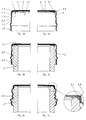
- the capsule 1 is shown in detail in FIG. 2a (left half of a cross section) and that as it looks before it is placed on the bottle neck 3 (see FIG. 2b) becomes.
- it has a flat bottom 1.1 and one essentially cylindrical jacket 1.2.
- the transition area 1.4 between Bottom 1.1 and jacket 1.2 is slightly rounded.
- In the jacket 1.2 is a circumferential Rib 1.3 molded. It protrudes inwards and thereby reduces the free cross section.
- a safety ring 1.5 At the (in Fig. 2a - c lower) edge of the jacket 1.2 is known per se Way prepared a safety ring 1.5.
- a sealing insert 2 made of plastic on the bottom 1.1 appropriate. According to a preferred embodiment, it covers the floor 1.1 completely. In a center area 2.1, it is very thin (e.g. 3/10 mm). In an annular sealing area 2.2, the thickness is approximately twice as much large (e.g. 5/10 - 7/10 mm). According to the invention, the sealing insert extends 2 to the coat 1.2. The transition area 1.4 is thus also covered. In the present example, the edge 2.3 of the sealing insert 2 is even along the Sheath 1.2 (in the representation of Fig. 2a: pulled down).
- sealing insert 2 wherever it is on the inside the capsule (be it at the bottom 1.1, at the transition area 1.4 or at the jacket 1.2), is also attached to it.
- Fig. 2b the capsule 1 is placed on the bottle neck 3.
- the sealing area 2.2 lies on the upper edge 3.1 of the bottle neck 3.
- the transition area 1.4 lies but not yet on the bottleneck 3.
- the bottle neck 3 has a thread 3.2 and a collar 3.3.
- 2c shows the bottle in the closed state.
- the transition area 1.4 has been bent in such a way that it fits with the sealing area 2.2 to the bottle neck 3 hugs.
- the safety ring 1.5 is shaped around the collar 3.3, so it has to be broken to open the clasp.
- the jacket 1.2 is also formed on the thread 3.2 of the bottle neck 3, whereby the capsule 1 comes to a corresponding screw thread 1.6.
- the capsule 4 has essentially the same shape as in the invention. Differently is the sealing insert 5. It has a bulge on the outer edge 5.1 on. In addition, it ends at a certain distance from the jacket 4.2, so that in Transition area 4.4 there is a gap 6.
- the bead 5.1 is crushed. This poses the risk that the plastic cracks and is no longer tight.
- the transition region 4.4 is shown enlarged in FIG. 1c.
- the bead 5.1 likes here Although it lies against the inside of the transition area 4.4, it will not be liable (since it is cold worked). Parts that break off the edge of the sealing insert can fall into the product. This is another important difference from the invention.
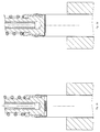
- the starting position is shown in FIG. 3a.
- the capsule 1 rests with its opening on top of a support 7 (presser).
- a portion 12 of the sealing material is deposited in the center of the capsule 1 been.
- the ratio of height H to cross dimension D (diameter) is in on the order of 1 or less so that the portion 12 cannot tip over.
- An embossing stamp is located on the same geometric axis as the carrier 7 8. It has an embossing surface 8.1 on its lower side facing the capsule 1 on and is in a conventional manner with a channel 11 for a cooling or heating liquid Mistake.
- a limiting sleeve 9 is coaxially displaceable stored. It has an edge 9.1, which is opposite in the rest position the embossing surface 8.1 protrudes downwards (for example by 1 - 2 mm). That edge 9.1 is made as thin as possible.
- a spring 10 which the upper (or rear) Encloses part of the stamp 8, presses the limiting sleeve 9 below, so that - in the rest position - with its stop 9.3 on the shoulder 8.2 rests on the outside of the die 8.
- the outer diameter of the limiting sleeve 9 is selected so that it is straight can still be introduced into the capsule 1.
- edge 9.1 is preferred "straight", d. H. cylindrical without gradations or roundings.
- the carrier 7 is now raised against the die 8 (Fig. 3b), the limiting sleeve 9, whose outer diameter is only slightly smaller than the free inner diameter is the capsule 1, penetrates into the capsule 1.
- the portion 12 is now slowly crushed, being more or less even on the floor 1.1 begins to distribute (Fig. 3c). Long before the sealing material hit the edge of the embossing surface 8.1, the edge 9.1 of the limiting sleeve 9 stands on the floor 1.1 on.
- the carrier 7 is now pressed further against the stamp 8, so that the sealing material can flow up to the shell 1.2 of the capsule 1 (Fig. 3f).
- the sealing material can flow up to the shell 1.2 of the capsule 1 (Fig. 3f).
- Fig. 3f Depending on how is strongly pressed and how the outer edge of the edge 9.1 is shaped, climbs the material more or less up along the coat.
- the sealing insert 2 is now finished.
- the carrier 7 is lowered again, so that the capsule 1 can be removed.
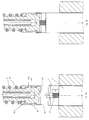
- Fig. 4 shows an example of a device for performing the above described Procedure. A single processing station of a turret is on average shown.
- the already mentioned support 7 is arranged by a (not shown) Controlled curve segment in its vertical movement.
- a scraper 13 can also be moved from below via a guide rod 14. This engages around the limiting sleeve 9 at a point that is straight during the re-embossing lies above the upper edge of the capsule 1. The scraper 13 moves on End of the re-stamping together with the carrier 7 down to prevent that the capsule 1 can stick to the die 8.
- Radially protruding elements are formed on the outside of the limiting sleeve 9, on which a driver 15 can engage to retract the limiting sleeve 9 to enable as part of the re-embossing.
- the driver 15 is in a fork bracket 16 of a two-armed lever 17 held.
- the lever 17 rotates about a horizontal bearing axis 18.
- a transmission rod 20 which is vertical is slidably mounted in the (rotating) turret structure 19.
- a roller guide 21 is attached, which on a curve segment 22 rolls.
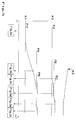
- Fig. 5 again illustrates the movements of the different parts.
- the axis of rotation of the turret is plotted on the abscissa.
- the ordinate gives the vertical Movement of the corresponding parts.
- Curve K1 shows the movement of the carrier 7 and the curve K2 that of the limiting sleeve 9.
- the cycle begins in the Starting position PU or PA (see Fig. 3a).
- the carrier 7 is raised continuously to the PV position (Fig. 3b - d).
- the limiting sleeve 9 which has not moved up to then) in the position PB raised (Fig. 3c - d).
- the post-embossing begins first the limiting sleeve 9 is pulled up to the PC position while the carrier 7 maintains the position PV (Fig. 3d - e), after which (when the Limiting sleeve 9) the carrier 7 again a little upwards in the position Press PN.
- K3 represents the course of the curve segment 22, which is described by the Lever mechanism (roller guide 21, transmission rod 20, lever 17, bearing 18, Fork bracket 16, driver 15) in the desired movement of the limiting sleeve is implemented.
- the embossing force can be somewhat reduced if necessary before the limiting sleeve 9 is withdrawn be reduced.
- the carrier 7 is then correspondingly moved from the position PV (FIG. 3d). slightly lowered, only raised to the PN position during the re-embossing (Fig. 3e - f) to become.
- the stamp does not need to be installed in a fixed position. If necessary, he can be easily vertically movable to be lowered into the capsule will.
- the limiting sleeve can also be actuated by other means instead of mechanical ones will.
- An electromagnet is mentioned as an example, which is used in the post-embossing Current is applied and thus pulls back the sleeve.
- the invention creates a capsule has been, even when using materials that are more difficult to process seals tightly as a sealing insert with high reliability.
Abstract
Description
Die Erfindung betrifft eine Verschlusskapsel, insbesondere für Glas- oder Kunststoffflaschen, mit einer auf einer Innenseite auf einem Boden der Verschlusskapsel angebrachten, geprägten Dichtungseinlage aus Kunststoff. Weiter bezieht sich die Erfindung auf ein Verfahren und eine Vorrichtung zur Herstellung einer solchen Verschlusskapsel. The invention relates to a closure capsule, in particular for glass or plastic bottles, with a capsule attached to the inside of a bottom of the cap, embossed sealing insert made of plastic. The invention further relates to a method and an apparatus for producing such a capsule.
Getränkeflaschen aus Glas oder Kunststoff werden mit einer Metallkapsel (z. B. aus Aluminium) bzw. einer Kunststoffkapsel verschlossen. Auf dem Boden der Kapsel ist eine Dichtung aus Kunststoff angebracht. Diese stellt die Dichtigkeit des Verschlusses sicher. Die Haltbarkeit des Flascheninhalts hängt folglich von der Qualität und der Lebensdauer der Dichtung ab. Es versteht sich, dass die primären Kriterien für die Auswahl des Dichtungsmaterials Geschmacksneutralität und Gesundheitsverträglichkeit sein müssen. Dies bringt es mit sich, dass die Merkmale der Verarbeitbarkeit nicht nach Belieben festgelegt werden können, sondern oft als gegeben hingenommen werden müssen.Beverage bottles made of glass or plastic are made with a metal capsule (e.g. made of Aluminum) or a plastic capsule. On the bottom of the capsule is a plastic seal attached. This ensures the tightness of the closure for sure. The shelf life of the bottle contents therefore depends on the quality and the Life of the seal. It is understood that the primary criteria for the Selection of the sealing material taste neutrality and health compatibility have to be. This entails that the characteristics of workability are not can be determined at will, but are often accepted as given have to.
Beim Anbringen des Verschlusses auf der Getränkeflasche erfährt die Dichtungseinlage der Verschlusskapsel eine starke mechanische Belastung. Entstehen Risse im Material, dann muss die Verschlusskapsel wieder entfernt werden. Die Qualität der Dichtung ist also von zentraler Bedeutung.When the cap is attached to the beverage bottle, the sealing insert is exposed the capsule has a strong mechanical load. Cracks appear in the Material, then the capsule must be removed. The quality of the So poetry is of central importance.
Seit einiger Zeit besteht nun auch das Bestreben, auf die Verwendung von PVC-haltigen Kunststoffen zu verzichten. Die Prozesse zur Verarbeitung von PVC-Kunststoffdichtungen sind aber häufig nicht ohne weiteres auf PVC-freie Kunststoffe umzustellen, da sich die PVC-freien Kunststoffe z. T. ziemlich anders verhalten (z. B. hinsichtlich Fliessfähigkeit). Entsprechend gibt es auch so unterschiedliche Herstellungsverfahren wie z. B. das Schleuder- und das Prägeverfahren.For some time now there has been an effort to use PVC-containing To dispense with plastics. The processes for processing PVC plastic seals Often, however, it is not easy to switch to PVC-free plastics. since the PVC-free plastics z. T. behave quite differently (e.g. regarding Flowability). Accordingly, there are different manufacturing processes such as B. the spin and embossing process.
Eine Vorrichtung zum Anbringen einer Dichtung im Inneren eines Flaschenverschlusses durch Prägen ist z. B. aus der EP 0 499 108 A1 (Japan Crown Cork) bekannt. Der Verschluss (32) wird auf einen vertikal bewegbaren Stössel (206) eines Drehturms gebracht und dort zentriert. Dann wird er nach oben gegen eine in vertikaler Richtung ortsfeste Begrenzungshülse (118) gefahren, welche den äusseren Rand der anzubringenden ringförmigen Dichtung definieren wird. In der Begrenzungshülse (118) ist ein in vertikaler Richtung leicht gefederter Stempel (120) gelagert. Dieser wird das Zentrum der Verschlusskapsel (32) grossflächig abdecken.A device for attaching a seal inside a bottle stopper by stamping z. B. from EP 0 499 108 A1 (Japan Crown Cork) known. Of the Closure (32) is on a vertically movable plunger (206) of a turret brought and centered there. Then he turns up against one in the vertical direction stationary limiting sleeve (118) driven, which the outer edge of the to be attached will define an annular seal. In the limiting sleeve (118) is a Stored lightly sprung stamp (120) in the vertical direction. This becomes the center Cover the capsule (32) over a large area.
Das Dichtungsmaterial (204) wird von oben in einen zwischen Stempel (120) und Begrenzungshülse (118) gebildeten Ringraum eingeführt und durch eine im Ringraum verfahrbare Prägehülse (116) nach unten in die Verschlusskapsel (32) gebracht. Unter dem Druck der Prägehülse (116) verteilt sich das Dichtungsmaterial gleichmässig auf dem Boden der Kapsel. Überschüssiges Material kann sich unter eine anhebbare Überschusskompensationshülse (114) schieben, welche den Ringraum gegen den Stempel (120) hin begrenzt.The sealing material (204) is from above into one between the punch (120) and the limiting sleeve (118) introduced annulus and by one in the annulus movable embossing sleeve (116) brought down into the sealing capsule (32). Under the pressure of the embossing sleeve (116) distributes the sealing material evenly the bottom of the capsule. Excess material can become liftable Slide excess compensation sleeve (114), which the annular space against the Stamp (120) limited.
Ein im Prinzip ähnliches Prägeverfahren ist z. B. auch aus der EP 0 207 385 A3 bekannt. Allerdings wird bei diesem das Dichtungsmaterial in einer vorangehenden Station in Form eines Tropfens im Zentrum der Kapsel deponiert, so dass nicht eine ring-, sondern eine scheibenförmige Dichtungseinlage entsteht.A stamping process which is similar in principle is e.g. B. also known from EP 0 207 385 A3. However, in this the sealing material is in a previous station deposited in the form of a drop in the center of the capsule, so that not a ring, but a disc-shaped sealing insert is created.
Die bekannten Verschlüsse vermögen nach wie vor nicht vollständig zu befriedigen.The known closures are still not completely satisfactory.
Aufgabe der Erfindung ist es daher, einen Verschluss anzugeben, der besser und beständiger als die bekannten ist. Weiter ist es Aufgabe der Erfindung, ein Verfahren und eine Vorrichtung zur Herstellung eines solchen Verschlusses anzugeben.The object of the invention is therefore to provide a closure that is better and more durable than the known one. It is a further object of the invention, a method and to provide a device for producing such a closure.
Die Lösung der Aufgabe ist durch die Merkmale des Anspruchs 1 definiert. Gemäss
der Erfindung zeichnet sich die Verschlusskapsel dadurch aus, dass sich die auf dem
Boden der Kapsel angebrachte Dichtung zumindest bis an den Mantel erstreckt und
dabei flächig haftend mit der Innenseite der Kapsel verbunden ist. Im Unterschied zum
Stand der Technik besteht also kein Abstand zwischen Mantel und Dichtung. Vorzugsweise
ist das Dichtungsmaterial sogar ein wenig am Mantel hochgezogen. The solution to the problem is defined by the features of
Beim Anbringen des Verschlusses auf der Flasche wird der Übergangsbereich zwischen Boden und Mantel verformt (d. h. er wird an die Kontur der Flaschenöffnung angeformt). Indem nun bei der Erfindung die Dichtung sich bis in den Übergangsbereich erstreckt, kann sie verhältnismässig dünn ausgebildet sein. Beim Verformen des Übergangsbereiches kann die Dichtung somit problemlos folgen, ohne die Gefahr von Rissbildung.When the cap is attached to the bottle, the transition area between Bottom and jacket deformed (i.e., it will conform to the contour of the bottle opening molded). In the invention, the seal extends into the transition area extends, it can be made relatively thin. When deforming the The transition area can thus easily follow the seal without the risk of Cracking.
Im Gegensatz dazu ist bei den bekannten Dichtungen ein Wulst vorgesehen, welcher beim Anbringen des Verschlusses stark verformt (insbesondere gequetscht) wird, was zu den oben beschriebenen Problemen (Rissbildung, Bruchgefahr etc.) führen kann.In contrast, a bead is provided in the known seals, which when attaching the closure is deformed (especially crushed) what can lead to the problems described above (cracking, risk of breakage, etc.).
Dadurch dass die Dichtung ganzflächig an der Kapselinnenseite klebt, besteht im übrigen auch nicht die Gefahr, dass Teile aus der Dichtung ausbrechen und in das Füllgut fallen können.The fact that the seal sticks to the inside of the capsule over the entire surface exists there is also no risk of parts breaking out of the seal and into the contents can fall.
Gemäss einer bevorzugten Ausführungsform überzieht das Dichtungsmaterial schichtartig den ganzen Boden. In der Mitte kann die Dicke der Schicht sehr klein sein (z. B. 3/10 mm), da in diesem Bereich keine Dichtungsfunktion realisiert werden muss. Je geringer die Dicke, desto mehr Material kann eingespart werden. In einem ringförmigen Randbereich und im Übergangsbereich (d. h. dort wo der gasdichte Abschluss erstellt werden muss) ist die Schichtdicke grösser (z. B. etwa doppelt so gross) angesetzt (z. B. 5/10 - 7/10 mm).According to a preferred embodiment, the sealing material is coated in layers the whole floor. In the middle, the thickness of the layer can be very small (e.g. 3/10 mm), since no sealing function has to be implemented in this area. Each the smaller the thickness, the more material can be saved. In an annular Edge area and in the transition area (i.e. where the gas-tight seal must be created), the layer thickness is set to be greater (e.g. approximately twice as large) (e.g. 5/10 - 7/10 mm).
Der Mantel der Verschlusskapsel kann über ein Gewinde verfügen, entsprechend demjenigen am Flaschenhals (die Kapsel kann also auf- und zugeschraubt werden). Nur nebenbei sei bemerkt, dass das Gewinde erst zuletzt angebracht wird, nämlich dann wenn der Verschluss auf den Flaschenhals aufgesetzt wird. Damit der Verschluss mit den Fingern gut erfasst werden kann, kann auch eine Rändelung angebracht sein. Diese ist typischerweise durch eine nach innen ragende, umlaufende Sicke begrenzt. Es ist darauf hinzuweisen, dass sich die Dichtung bei der erfindungsgemässen Verschlusskapsel auch dann bis zum Mantel erstreckt, wenn der durch die genannte Sicke definierte freie Innenquerschnitt der Kapsel kleiner ist als der Durchmesser des Bodens.The casing of the capsule can be threaded accordingly the one on the bottle neck (the capsule can therefore be screwed on and off). Incidentally, it should be noted that the thread is only attached last, namely then when the cap is placed on the bottle neck. So that the closure Knurling can also be done with the fingers be. This is typically due to an inwardly projecting, circumferential one Beading limited. It should be noted that the seal in the inventive Sealing capsule also extends to the jacket if the through the called bead defined free inner cross section of the capsule is smaller than the diameter of the floor.
Die Verschlusskapsel besteht z. B. aus Aluminium oder einem anderen gut formbaren Metall. Als Dichtungsmaterial wird mit Vorteil ein PVC-freier Kunststoff verwendet. Dies namentlich aus gesundheits- und umwelttechnischen Gründen.The capsule consists, for. B. made of aluminum or another well formable Metal. A PVC-free plastic is advantageously used as the sealing material. This namely for health and environmental reasons.
Zur Herstellung der genannten Verschlusskapsel wird gemäss der Erfindung wie folgt vorgegangen:According to the invention, the capsule is manufactured as follows proceeded:
Zuerst wird eine Portion Dichtungsmaterial auf dem Boden der Kapsel deponiert. Dann wird das Dichtungsmaterial mit einem Prägestempel mit Begrenzungshülse im Rahmen einer Vorprägung flächig auf dem Boden verteilt. Danach wird die Begrenzungshülse angehoben (d. h. vom Boden der Kapsel abgehoben), um im Rahmen einer Nachprägung das Dichtungsmaterial zumindest bis an den Mantel zu treiben.First, a portion of sealing material is placed on the bottom of the capsule. Then the sealing material with an embossing stamp with a limiting sleeve in the frame an embossing distributed over the floor. Then the limiting sleeve raised (i.e., lifted off the bottom of the capsule) to accommodate a Post-embossing to drive the sealing material at least up to the jacket.
Die Erfindung stellt die Dichtung also mit einem Prägeverfahren her, wobei die Ausformung in zwei Teilschritten erfolgt. Im ersten findet eine gleichmässige Verteilung der (ursprünglich z. B. pfropfenförmigen) Portion statt. Im zweiten wird die Begrenzungshülse gezielt entfernt und das Material bis in den Übergangsbereich (oder sogar geringfügig darüber hinaus) gepresst.The invention therefore produces the seal using an embossing process, the shaping done in two steps. In the first one finds an even distribution of the (originally e.g. plug-shaped) portion instead. In the second, the limiting sleeve deliberately removed and the material into the transition area (or even slightly beyond) pressed.
Das Verfahren lässt sich am besten und effizientesten mit einem Drehturm implementieren. Dabei ist es von Vorteil, die Begrenzungshülse zur Durchführung der Nachprägung mechanisch gesteuert anzuheben.The best and most efficient way to implement the process is with a rotating tower. It is advantageous to use the limiting sleeve to carry out the re-stamping mechanically controlled lifting.
Das Dichtungsmaterial wird an einer Extruderdüse abgeschnitten und möglichst im Zentrum der Kapsel deponiert. Die Portion sollte möglichst flach sein. Da das Material aber zähflüssig ist, kann es nicht gut als dünne Scheibe abgeschnitten werden. Mit Vorteil wird aber darauf geachtet, dass die Länge der wurstförmig extrudierten Portion kleiner als deren Durchmesser ist. Auf diese Weise kann verhindert werden, dass die Portion nach dem Deponieren umkippen kann. Die zentrierte Position stellt nämlich sicher, dass beim nachfolgenden Vorprägen eine gleichmässige Verteilung des Dichtungsmaterials erreicht wird.The sealing material is cut off on an extruder nozzle and if possible in the Center of the capsule deposited. The portion should be as flat as possible. Because the material but is viscous, it cannot be cut off as a thin slice. With However, the advantage is that the length of the sausage-extruded portion is smaller than their diameter. In this way, the Portion can tip over after depositing. The centered position is namely sure that the sealing material is evenly distributed during the subsequent pre-stamping is achieved.
Eine Vorrichtung zur Durchführung des Verfahrens verfügt über einen in die Verschlusskapsel einführbaren Prägestempel mit einer diesen umschliessenden Begrenzungshülse sowie ein Trägerelement für die Verschlusskapsel. Gemäss der Erfindung ist die Verschlusskapsel kontrolliert anhebbar, um bei der Nachprägung das Ausprägen der Dichtung bis in den Übergangsbereich zum Mantel am Rand des Bodens zu ermöglichen.A device for performing the method has one in the sealing capsule insertable embossing stamp with a limiting sleeve surrounding it and a carrier element for the capsule. According to the invention the capsule can be raised in a controlled manner so that it can be embossed during the re-embossing the seal up to the transition area to the jacket at the edge of the floor enable.
Die Begrenzungshülse wird z. B. durch eine Feder in einer gegenüber der Prägefläche des Prägestempels überstehenden Stellung gehalten und kann durch eine Mechanik kontrolliert zurückgezogen werden. Der Prägestempel kann in vertikaler Richtung ortsfest oder leicht gefedert sein. Die Verschlusskapsel wird dann von unten mit dem Trägerelement (Andrücker) zum Prägestempel gebracht. Das Anheben der Begrenzungshülse wird vorzugsweise durch eine Kurvensteuerung kontrolliert. Bei Drehtürmen lassen sich auf diese Weise grosse Verarbeitungsgeschwindigkeiten bei gleichzeitig hoher Präzision erreichen.The limiting sleeve is z. B. by a spring in a compared to the embossing surface the stamping protruding position held and can by a mechanism withdrawn in a controlled manner. The stamp can be in the vertical direction be stationary or slightly sprung. The capsule is then from below with the Carrier element (presser) brought to the embossing stamp. Raising the limiting sleeve is preferably controlled by a curve control. With turrets this way, high processing speeds can be achieved at the same time achieve high precision.
Selbstverständlich sind auch andere Konstruktionen möglich. Die Begrenzungshülse kann z. B. auch elektrisch, magnetisch oder pneumatisch gesteuert bewegt werden. Im übrigen ist nicht ausgeschlossen, dass der Prägestempel verfahrbar ist.Of course, other constructions are also possible. The limiting sleeve can e.g. B. can also be moved electrically, magnetically or pneumatically controlled. in the It is not excluded that the die can be moved.
Die Mechanik zum Betätigen der Begrenzungshülse kann einen Hebelmechanismus umfassen, der an aussenseitig der Hülse vorgesehenen Elementen angreift und der von einer auf der Kurvenschiene laufenden Rolle geführt wird.The mechanism for actuating the limiting sleeve can be a lever mechanism comprise, which engages on the outside of the sleeve provided elements and the is guided by a roller running on the cam track.
Aus der nachfolgenden Detailbeschreibung und der Gesamtheit der Patentansprüche ergeben sich weitere vorteilhafte Ausführungsformen und Merkmalskombinationen der Erfindung. From the following detailed description and the entirety of the claims there are further advantageous embodiments and combinations of features of the Invention.
Die zur Erläuterung des Ausführungsbeispiels verwendeten Zeichnungen zeigen:
- Fig. 1a - c
- Eine schematische Darstellung des bekannten Verschlusses beim Aufbringen auf eine Flasche;
- Fig. 2a - c
- eine schematische Darstellung des erfindungsgemässen Verschlusses beim Aufbringen auf eine Flasche;
- Fig. 3a - f
- eine schematische Darstellung des Verfahrens zur Herstellung der erfindungsgemässen Verschlusskapsel;
- Fig. 4
- eine schematische Darstellung einer Vorrichtung zum Prägen der erfindungsgemässen Dichtung;
- Fig. 5
- eine schematische Darstellung eines Kinematikdiagramms für die Ansteuerung der Vorrichtung gemäss Fig. 4.
- 1a-c
- A schematic representation of the known closure when applied to a bottle;
- 2a-c
- a schematic representation of the closure according to the invention when applied to a bottle;
- 3a-f
- a schematic representation of the method for producing the closure capsule according to the invention;
- Fig. 4
- a schematic representation of a device for embossing the seal according to the invention;
- Fig. 5
- 3 shows a schematic representation of a kinematic diagram for the control of the device according to FIG.
Grundsätzlich sind in den Figuren gleiche Teile mit gleichen Bezugszeichen versehen.In principle, the same parts are provided with the same reference symbols in the figures.
Anhand der Figuren 2a - c soll als erstes das Prinzip des erfindungsgemässen Verschlusses erläutert werden.The principle of the closure according to the invention is intended first of all with reference to FIGS. 2a-c are explained.
In Fig. 2a ist die Kapsel 1 ausschnittsweise (linke Hälfte eines Querschnitts) dargestellt
und zwar so, wie sie aussieht, bevor sie auf den Flaschenhals 3 (vgl. Fig. 2b) aufgesetzt
wird. Im vorliegenden Beispiel verfügt sie über einen flachen Boden 1.1 und einen
im wesentlichen zylindrischen Mantel 1.2. Der Übergangsbereich 1.4 zwischen
Boden 1.1 und Mantel 1.2 ist leicht abgerundet. Im Mantel 1.2 ist eine umlaufende
Sicke 1.3 eingeformt. Sie ragt nach innen und verkleinert dadurch den freien Querschnitt.
Am (in Fig. 2a - c unteren) Rand des Mantels 1.2 ist in an sich bekannter
Weise ein Sicherheitsring 1.5 vorbereitet.The
Innenseitig der Kapsel 1 ist auf dem Boden 1.1 eine Dichtungseinlage 2 aus Kunststoff
angebracht. Gemäss einer bevorzugten Ausführungsform deckt sie den Boden 1.1
vollständig ab. In einem Zentrumsbereich 2.1 ist sie sehr dünn ausgebildet (z. B.
3/10 mm). In einem ringförmigen Dichtungsbereich 2.2 ist die Dicke etwa doppelt so
gross (z. B. 5/10 - 7/10 mm). Gemäss der Erfindung erstreckt sich die Dichtungseinlage
2 bis zum Mantel 1.2. Der Übergangsbereich 1.4 wird somit ebenfalls abgedeckt.
Im vorliegenden Beispiel ist sogar der Rand 2.3 der Dichtungseinlage 2 entlang des
Mantels 1.2 (in der Darstellung der Fig. 2a: nach unten) gezogen.On the inside of the
Es ist zu beachten, dass die Dichtungseinlage 2 überall dort, wo sie an der Innenseite
der Kapsel (sei es am Boden 1.1, am Übergangsbereich 1.4 oder am Mantel 1.2) anliegt,
auch mit ihr haftend verbunden ist.It should be noted that the sealing
In Fig. 2b ist die Kapsel 1 auf den Flaschenhals 3 aufgesetzt. Der Dichtungsbereich
2.2 liegt auf der Oberkante 3.1 des Flaschenhalses 3. Der Übergangsbereich 1.4 liegt
dabei aber noch nicht am Flaschenhals 3 an. In an sich bekannter Weise sind aussenseitig
des Flaschenhalses 3 ein Gewinde 3.2 und ein Kragen 3.3 ausgebildet.In Fig. 2b, the
In Fig. 2c ist die Flasche im verschlossenen Zustand dargestellt. Der Übergangsbereich
1.4 wurde so abgebogen, dass er sich mit dem Dichtungsbereich 2.2 an den Flaschenhals
3 anschmiegt. Der Sicherheitsring 1.5 ist um den Kragen 3.3 herum geformt,
so dass er zum Öffnen des Verschlusses gebrochen werden muss. Schliesslich
ist in Fig. 2c auch der Mantel 1.2 an das Gewinde 3.2 des Flaschenhalses 3 angeformt,
wodurch die Kapsel 1 zu einem entsprechenden Schraubgewinde 1.6 kommt.2c shows the bottle in the closed state. The transition area
1.4 has been bent in such a way that it fits with the sealing area 2.2 to the
In Fig. 1a - c ist zum Vergleich ein Verschluss nach dem Stand der Technik dargestellt.
Die Kapsel 4 hat im wesentlichen dieselbe Form wie bei der Erfindung. Unterschiedlich
ist dagegen die Dichtungseinlage 5. Sie weist nämlich am äusseren Rand einen Wulst
5.1 auf. Zudem endet sie in einem gewissem Abstand zum Mantel 4.2, so dass im
Übergangsbereich 4.4 ein Spalt 6 vorhanden ist. Beim Anformen der Kapsel 4 (vgl.
Fig. 1c und 1d) wird der Wulst 5.1 zerquetscht. Dies bringt die Gefahr mit sich, dass
der Kunststoff Risse bildet und nicht mehr dicht ist.1a-c shows a closure according to the prior art for comparison.
The
In Fig. 1c ist der Übergangsbereich 4.4 vergrössert dargestellt. Der Wulst 5.1 mag hier zwar an der Innenseite des Übergangsbereiches 4.4 anliegen, wird aber nicht haften (da er kaltverformt ist). Teile, die vom Rand der Dichtungseinlage abbrechen, können ins Füllgut fallen. Hierin liegt also ein weiterer wichtiger Unterschied zur Erfindung.The transition region 4.4 is shown enlarged in FIG. 1c. The bead 5.1 likes here Although it lies against the inside of the transition area 4.4, it will not be liable (since it is cold worked). Parts that break off the edge of the sealing insert can fall into the product. This is another important difference from the invention.
Anhand der Fig. 3a - f soll nun das Verfahren zur Herstellung der erfindungsgemässen
Dichtungseinlage 2 erläutert werden.3a-f, the method for producing the
In Fig. 3a ist die Ausgangsstellung gezeigt. Die Kapsel 1 ruht mit ihrer Öffnung nach
oben auf einem Träger 7 (Andrücker). In einem (nicht dargestellten) vorangegangenen
Arbeitsschritt ist eine Portion 12 des Dichtungsmaterials im Zentrum der Kapsel 1 deponiert
worden. Das Verhältnis von Höhe H zu Querabmessung D (Durchmesser) ist in
der Grössenordnung von 1 oder kleiner, damit die Portion 12 nicht umkippen kann.The starting position is shown in FIG. 3a. The
Auf derselben geometrischen Achse wie der Träger 7 befindet sich ein Prägestempel
8. Er weist an seiner unteren, der Kapsel 1 zugewandten Seite eine Prägefläche 8.1
auf und ist in an sich bekannter Weise mit einem Kanal 11 für eine Kühl- oder Heizflüssigkeit
versehen.An embossing stamp is located on the same geometric axis as the
Auf der Mantelseite des Prägestempels 8 ist eine Begrenzungshülse 9 koaxial verschiebbar
gelagert. Sie hat einen Rand 9.1, welcher in der Ruhestellung gegenüber
der Prägefläche 8.1 nach unten vorsteht (um beispielsweise 1 - 2 mm). Dieser Rand
9.1 ist so dünn wie möglich ausgebildet. Eine Feder 10, welche den oberen (bzw. hinteren)
Teil des Prägestempels 8 umschliesst, drückt die Begrenzungshülse 9 nach
unten, so dass sie - in der Ruhestellung - mit ihrem Anschlag 9.3 auf der Schulter 8.2
an der Aussenseite des Prägestempels 8 aufliegt. On the jacket side of the
Der Aussendurchmesser der Begrenzungshülse 9 ist so gewählt, dass diese gerade
noch in die Kapsel 1 hineingeführt werden kann. Innenseitig ist der Rand 9.1 vorzugsweise
"gerade", d. h. ohne Abstufungen oder Abrundungen zylindrisch.The outer diameter of the limiting
Der Träger 7 wird nun gegen den Prägestempel 8 angehoben (Fig. 3b), wobei die Begrenzungshülse
9, deren Aussendurchmesser nur geringfügig kleiner als der freie Innendurchmesser
der Kapsel 1 ist, in die Kapsel 1 eindringt. Die Portion 12 wird nun
langsam zerquetscht, wobei sie sich mehr oder weniger gleichmässig auf dem Boden
1.1 zu verteilen beginnt (Fig. 3c). Noch lange bevor das Dichtungsmaterial den Rand
der Prägefläche 8.1 erreicht, steht der Rand 9.1 der Begrenzungshülse 9 auf dem Boden
1.1 auf.The
Die Bewegung des Trägers 7 geht indessen weiter. Die Begrenzungshülse 9 wird dadurch
aus ihrer Ruhestellung hinaus nach oben gegen die Kraft der Feder 10 geschoben
(Fig. 3d). Schliesslich kommt der Zeitpunkt, wo das Dichtungsmaterial sich innerhalb
der Begrenzungshülse 9 gleichmässig verteilt hat (Fig. 3d). Die Vorprägung ist
damit beendet.The movement of the
Nun folgt die Nachprägung (Fig. 3e und 3f). Die Begrenzungshülse 9 wird dabei zumindest
soweit nach oben gezogen, dass der Rand 9.1 hinter der Prägefläche 8.1 verschwindet.
Der Übergangsbereich 1.4 wird folglich freigegeben.Now the post-embossing follows (Fig. 3e and 3f). The limiting
Der Träger 7 wird jetzt weiter gegen den Prägestempel 8 gepresst, so dass das Dichtungsmaterial
bis zum Mantel 1.2 der Kapsel 1 fliessen kann (Fig. 3f). Je nachdem wie
stark nachgepresst wird und wie die äussere Kante des Randes 9.1 geformt ist, klettert
das Material mehr oder weniger weit am Mantel entlang nach oben.The
Die Dichtungseinlage 2 ist damit fertig. Der Träger 7 wird wieder abgesenkt, so dass
die Kapsel 1 entfernt werden kann. The sealing
Fig. 4 zeigt beispielhaft eine Vorrichtung zur Durchführung des oben beschriebenen Verfahrens. Und zwar ist ein einzelner Bearbeitungsplatz eines Drehturms im Schnitt dargestellt.Fig. 4 shows an example of a device for performing the above described Procedure. A single processing station of a turret is on average shown.
Der bereits erwähnte Träger 7 wird durch ein weiter unten angeordnetes (nicht dargestelltes)
Kurvensegment in seiner vertikaler Bewegung gesteuert.The already mentioned
Ebenfalls von unten ist ein Abstreifer 13 über eine Führungsstange 14 bewegbar. Dieser
umgreift die Begrenzungshülse 9 an einer Stelle, die bei der Nachprägung gerade
oberhalb des oberen Randes der Kapsel 1 liegt. Der Abstreifer 13 bewegt sich am
Ende der Nachprägung zusammen mit dem Träger 7 nach unten, um zu verhindern,
dass die Kapsel 1 am Prägestempel 8 kleben bleiben kann.A
An der Aussenseite der Begrenzungshülse 9 sind radial vorstehende Elemente ausgebildet,
an denen ein Mitnehmer 15 angreifen kann, um ein Zurückziehen der Begrenzungshülse
9 im Rahmen der Nachprägung zu ermöglichen. Der Mitnehmer 15 ist in
einer Gabelhalterung 16 eines zweiarmigen Hebels 17 gehalten. Der Hebel 17 dreht
um eine horizontale Lagerachse 18. Auf das der Gabelhalterung 16 gegenüberliegende
Ende des Hebels 17 kann eine Übertragungsstange 20 drücken, welche vertikal
verschiebbar im (rotierenden) Drehturmaufbau 19 gelagert ist. Am oberen Ende der
Übertragungsstange 20 ist eine Rollenführung 21 angebracht, welche auf einem Kurvensegment
22 abrollt.Radially protruding elements are formed on the outside of the limiting
Fig. 5 veranschaulicht nochmals die Bewegungen der verschiedenen Teile. Auf der
Abszisse ist der Drehwinkel des Drehturms aufgetragen. Die Ordinate gibt die vertikale
Bewegung der entsprechenden Teile an. Die Kurve K1 zeigt die Bewegung des Trägers
7 und die Kurve K2 diejenige der Begrenzungshülse 9. Der Zyklus beginnt in der
Ausgangsstellung PU bzw. PA (vgl. Fig. 3a). Der Träger 7 wird kontinuierlich angehoben
bis zur Stellung PV (Fig. 3b - d). Im letzten Teil dieser Aufwärtsbewegung wird
auch die Begrenzungshülse 9 (welche sich bis dahin nicht bewegt hat) nach oben in
die Stellung PB angehoben (Fig. 3c - d). Dann beginnt die Nachprägung, bei welcher
zunächst die Begrenzungshülse 9 in die Stellung PC nach oben gezogen wird, während
der Träger 7 die Stellung PV beibehält (Fig. 3d - e), um danach (bei zurückgezogener
Begrenzungshülse 9) den Träger 7 nochmals ein Stück nach oben in die Stellung
PN zu pressen.Fig. 5 again illustrates the movements of the different parts. On the
The axis of rotation of the turret is plotted on the abscissa. The ordinate gives the vertical
Movement of the corresponding parts. Curve K1 shows the movement of the
K3 stellt den Verlauf des Kurvensegments 22 dar, welcher durch den beschriebenen
Hebelmechanismus (Rollenführung 21, Übertragungsstange 20, Hebel 17, Lager 18,
Gabelhalterung 16, Mitnehmer 15) in die gewünschte Bewegung der Begrenzungshülse
umgesetzt wird.K3 represents the course of the
Die Prägekraft kann vor dem Zurückziehen der Begrenzungshülse 9 bei Bedarf etwas
reduziert werden. Entsprechend wird dann der Träger 7 aus der Stellung PV (Fig. 3d)
etwas abgesenkt, um erst bei der Nachprägung (Fig. 3e - f) bis zur Stellung PN angehoben
zu werden.The embossing force can be somewhat reduced if necessary before the limiting
Es ist klar, dass sich die beschriebenen Ausführungsbeispiele in verschiedenen
Aspekten modifizieren lassen. Insbesondere ist hervorzuheben, dass die in Fig. 4 gezeigten
konstruktiven Einzelheiten zwar bevorzugt aber nicht unerlässlich sind. Anstelle
des Hebelmechanismus kann z. B. eine Stangenführung sinngemäss zu derjenigen
des Abstreifers 13 vorgesehen sein (während der Abstreifer ebenso gut von oben
angesteuert werden kann).It is clear that the described exemplary embodiments differ in different ways
Have aspects modified. In particular, it should be emphasized that those shown in FIG. 4
constructive details are preferred but not essential. Instead of
the lever mechanism can e.g. B. a rod guide analogous to that
of the
Der Prägestempel braucht nicht in einer fixen Stellung montiert zu sein. Er kann gewünschtenfalls ohne weiteres vertikal verfahrbar sein, um in die Kapsel abgesenkt zu werden.The stamp does not need to be installed in a fixed position. If necessary, he can be easily vertically movable to be lowered into the capsule will.
Die Begrenzungshülse kann statt mit mechanischen auch mit anderen Mitteln betätigt werden. Als Beispiel sei ein Elektromagnet erwähnt, welcher bei der Nachprägung mit Strom beaufschlagt wird und so die Hülse zurückzieht.The limiting sleeve can also be actuated by other means instead of mechanical ones will. An electromagnet is mentioned as an example, which is used in the post-embossing Current is applied and thus pulls back the sleeve.
Während beim bevorzugten Verfahren gemäss Fig. 3a - f eine wurstähnliche Portion im Zentrum der Kapsel plaziert wird, sind auch Verfahren möglich, bei denen eine ringförmige Portion entlang des Randes des Bodens eingelegt wird (vgl. diesbezüglich die EP 0 499 108 A1).While in the preferred method according to FIGS. 3a-f a portion similar to sausage In the center of the capsule, procedures are also possible in which one ring-shaped portion is inserted along the edge of the bottom (cf. EP 0 499 108 A1).
Zusammenfassend ist festzustellen, dass durch die Erfindung eine Kapsel geschaffen worden ist, die auch bei der Verwendung von verarbeitungsmässig schwierigeren Materialien als Dichtungseinlage mit hoher Zuverlässigkeit dicht verschliesst.In summary, it can be stated that the invention creates a capsule has been, even when using materials that are more difficult to process seals tightly as a sealing insert with high reliability.
Claims (11)
dadurch gekennzeichnet, dass
characterized in that
dadurch gekennzeichnet, dass
characterized in that
Applications Claiming Priority (3)
| Application Number | Priority Date | Filing Date | Title |
|---|---|---|---|
| CH27697 | 1997-02-07 | ||
| CH276/97 | 1997-02-07 | ||
| CH27697 | 1997-02-07 |
Publications (2)
| Publication Number | Publication Date |
|---|---|
| EP0857660A1 true EP0857660A1 (en) | 1998-08-12 |
| EP0857660B1 EP0857660B1 (en) | 2002-02-06 |
Family
ID=4183310
Family Applications (1)
| Application Number | Title | Priority Date | Filing Date |
|---|---|---|---|
| EP97811031A Expired - Lifetime EP0857660B1 (en) | 1997-02-07 | 1997-12-30 | Method and apparatus for the manufacture of a closure cap |
Country Status (3)
| Country | Link |
|---|---|
| EP (1) | EP0857660B1 (en) |
| DE (1) | DE59706305D1 (en) |
| ES (1) | ES2171873T3 (en) |
Citations (3)
| Publication number | Priority date | Publication date | Assignee | Title |
|---|---|---|---|---|
| FR2130290A1 (en) * | 1971-03-15 | 1972-11-03 | Metal Closures Ltd | |
| JPS58142806A (en) * | 1982-02-19 | 1983-08-25 | Japan Crown Cork Co Ltd | Liner press forming device |
| DE4217254A1 (en) * | 1992-05-25 | 1993-12-02 | Schmalbach Lubeca | Closure for glass container - comprises screw cover of metal plate with inner varnishing and ring-shaped sealing mass |
Family Cites Families (2)
| Publication number | Priority date | Publication date | Assignee | Title |
|---|---|---|---|---|
| IT1202154B (en) * | 1985-06-24 | 1989-02-02 | Sacmi | EQUIPMENT FOR THE APPLICATION OF A GASKET INSIDE CAPS INCLUDING A BOWL, SUCH AS SCREW AND CROWN CAPS |
| JP3062829B2 (en) * | 1991-02-13 | 2000-07-12 | 日本クラウンコルク株式会社 | Annular liner molding equipment |
-
1997
- 1997-12-30 ES ES97811031T patent/ES2171873T3/en not_active Expired - Lifetime
- 1997-12-30 EP EP97811031A patent/EP0857660B1/en not_active Expired - Lifetime
- 1997-12-30 DE DE59706305T patent/DE59706305D1/en not_active Expired - Lifetime
Patent Citations (3)
| Publication number | Priority date | Publication date | Assignee | Title |
|---|---|---|---|---|
| FR2130290A1 (en) * | 1971-03-15 | 1972-11-03 | Metal Closures Ltd | |
| JPS58142806A (en) * | 1982-02-19 | 1983-08-25 | Japan Crown Cork Co Ltd | Liner press forming device |
| DE4217254A1 (en) * | 1992-05-25 | 1993-12-02 | Schmalbach Lubeca | Closure for glass container - comprises screw cover of metal plate with inner varnishing and ring-shaped sealing mass |
Non-Patent Citations (1)
| Title |
|---|
| PATENT ABSTRACTS OF JAPAN vol. 007, no. 261 (M - 257) 19 November 1983 (1983-11-19) * |
Also Published As
| Publication number | Publication date |
|---|---|
| DE59706305D1 (en) | 2002-03-21 |
| ES2171873T3 (en) | 2002-09-16 |
| EP0857660B1 (en) | 2002-02-06 |
Similar Documents
| Publication | Publication Date | Title |
|---|---|---|
| DE69726750T2 (en) | Method and device for producing a can lid groove | |
| DE60201504T2 (en) | METHOD AND DEVICE FOR INCLUDING THE OPENING OF A CONTAINER | |
| DE3705560C2 (en) | Filling valve mechanism for cans or similar containers | |
| DE2353209A1 (en) | DEEP-DRAWN CONTAINER AND PROCESS FOR ITS MANUFACTURING | |
| EP2058379A1 (en) | Method for manufacturing a closure | |
| DE4016350A1 (en) | METHOD AND DEVICE FOR REMOVING A GUARANTEE TAPE FROM A CAP | |
| DE4425675C3 (en) | Sealing cap | |
| EP0857660B1 (en) | Method and apparatus for the manufacture of a closure cap | |
| EP1107917A1 (en) | Method for producing a closing cap and closing cap produced according to said method | |
| EP0620164A1 (en) | Method for producing a closure for bottles or the like | |
| EP2996855B1 (en) | Method and device for pressing a sealing compound on the inside of a lid for containers | |
| DE1602512A1 (en) | Method and apparatus for manufacturing closure caps with continuations | |
| DE2123865B2 (en) | Filling element | |
| DE19625690C2 (en) | Process for producing a double-walled, cup-shaped glass container | |
| EP2935025B1 (en) | Method and device for applying indicia to containers | |
| CH636814A5 (en) | DEVICE FOR CLOSING A CONTAINER WITH A SEALING LID TO BE CLAMPED ABOVE THE EDGE OF A CONTAINER OPENING. | |
| DE10352672B4 (en) | Dual compound application in a cap, cap and punch | |
| EP1682424A1 (en) | Plastic coating of the end-inner area of a cap | |
| WO2019038237A1 (en) | Method and device for applying a sealing compound to the base and inner side of an annular wall of a cover for containers | |
| DE19545080A1 (en) | Pressing vessels against vessel filling machine | |
| DE3725609A1 (en) | Bottle filling machine in factory - has filler valve opened in two stages by pressure operated device and mechanical device | |
| DE102005031217A1 (en) | Filling element and filling machine of rotating design | |
| DE4411337A1 (en) | Procedure for forming slim container | |
| DE19614019A1 (en) | Formed sealing inlay for deep drawn bottle closure | |
| DE2624969C2 (en) | Screw cap for bottles, processes and mold cores for their production and deep-drawing die with several mold cores |
Legal Events
| Date | Code | Title | Description |
|---|---|---|---|
| PUAI | Public reference made under article 153(3) epc to a published international application that has entered the european phase |
Free format text: ORIGINAL CODE: 0009012 |
|
| AK | Designated contracting states |
Kind code of ref document: A1 Designated state(s): CH DE ES FR GB IT LI |
|
| AX | Request for extension of the european patent |
Free format text: AL;LT;LV;MK;RO;SI |
|
| 17P | Request for examination filed |
Effective date: 19990125 |
|
| AKX | Designation fees paid |
Free format text: CH DE ES FR GB IT LI |
|
| RBV | Designated contracting states (corrected) |
Designated state(s): CH DE ES FR GB IT LI |
|
| 17Q | First examination report despatched |
Effective date: 19991013 |
|
| RTI1 | Title (correction) |
Free format text: METHOD AND APPARATUS FOR THE MANUFACTURE OF A CLOSURE CAP |
|
| GRAG | Despatch of communication of intention to grant |
Free format text: ORIGINAL CODE: EPIDOS AGRA |
|
| GRAG | Despatch of communication of intention to grant |
Free format text: ORIGINAL CODE: EPIDOS AGRA |
|
| GRAH | Despatch of communication of intention to grant a patent |
Free format text: ORIGINAL CODE: EPIDOS IGRA |
|
| GRAH | Despatch of communication of intention to grant a patent |
Free format text: ORIGINAL CODE: EPIDOS IGRA |
|
| GRAA | (expected) grant |
Free format text: ORIGINAL CODE: 0009210 |
|
| REG | Reference to a national code |
Ref country code: GB Ref legal event code: IF02 |
|
| AK | Designated contracting states |
Kind code of ref document: B1 Designated state(s): CH DE ES FR GB IT LI |
|
| REG | Reference to a national code |
Ref country code: CH Ref legal event code: EP |
|
| REG | Reference to a national code |
Ref country code: CH Ref legal event code: NV Representative=s name: KELLER & PARTNER PATENTANWAELTE AG |
|
| REF | Corresponds to: |
Ref document number: 59706305 Country of ref document: DE Date of ref document: 20020321 |
|
| GBT | Gb: translation of ep patent filed (gb section 77(6)(a)/1977) |
Effective date: 20020515 |
|
| ET | Fr: translation filed | ||
| REG | Reference to a national code |
Ref country code: ES Ref legal event code: FG2A Ref document number: 2171873 Country of ref document: ES Kind code of ref document: T3 |
|
| PLBE | No opposition filed within time limit |
Free format text: ORIGINAL CODE: 0009261 |
|
| STAA | Information on the status of an ep patent application or granted ep patent |
Free format text: STATUS: NO OPPOSITION FILED WITHIN TIME LIMIT |
|
| 26N | No opposition filed |
Effective date: 20021107 |
|
| REG | Reference to a national code |
Ref country code: CH Ref legal event code: PFA Owner name: PACKSYS GLOBAL (SWITZERLAND) AG Free format text: OBERBURG ENGINEERING AG#EMMENTALSTRASSE 137#3414 OBERBURG (CH) -TRANSFER TO- PACKSYS GLOBAL (SWITZERLAND) AG#EMMENTALSTRASSE 137#3414 OBERBURG (CH) |
|
| REG | Reference to a national code |
Ref country code: GB Ref legal event code: 732E |
|
| REG | Reference to a national code |
Ref country code: ES Ref legal event code: PC2A |
|
| REG | Reference to a national code |
Ref country code: FR Ref legal event code: TP |
|
| PG25 | Lapsed in a contracting state [announced via postgrant information from national office to epo] |
Ref country code: IT Free format text: LAPSE BECAUSE OF NON-PAYMENT OF DUE FEES Effective date: 20071230 |
|
| PGFP | Annual fee paid to national office [announced via postgrant information from national office to epo] |
Ref country code: GB Payment date: 20101203 Year of fee payment: 14 |
|
| PGFP | Annual fee paid to national office [announced via postgrant information from national office to epo] |
Ref country code: DE Payment date: 20101201 Year of fee payment: 14 |
|
| PGFP | Annual fee paid to national office [announced via postgrant information from national office to epo] |
Ref country code: ES Payment date: 20101230 Year of fee payment: 14 |
|
| PGFP | Annual fee paid to national office [announced via postgrant information from national office to epo] |
Ref country code: IT Payment date: 20101229 Year of fee payment: 14 |
|
| PGRI | Patent reinstated in contracting state [announced from national office to epo] |
Ref country code: IT Effective date: 20110616 |
|
| PGFP | Annual fee paid to national office [announced via postgrant information from national office to epo] |
Ref country code: CH Payment date: 20111118 Year of fee payment: 15 Ref country code: FR Payment date: 20120106 Year of fee payment: 15 |
|
| PG25 | Lapsed in a contracting state [announced via postgrant information from national office to epo] |
Ref country code: IT Free format text: LAPSE BECAUSE OF NON-PAYMENT OF DUE FEES Effective date: 20111230 |
|
| REG | Reference to a national code |
Ref country code: ES Ref legal event code: FD2A Effective date: 20130704 |
|
| PG25 | Lapsed in a contracting state [announced via postgrant information from national office to epo] |
Ref country code: ES Free format text: LAPSE BECAUSE OF NON-PAYMENT OF DUE FEES Effective date: 20111231 |
|
| REG | Reference to a national code |
Ref country code: CH Ref legal event code: PL |
|
| GBPC | Gb: european patent ceased through non-payment of renewal fee |
Effective date: 20121230 |
|
| REG | Reference to a national code |
Ref country code: FR Ref legal event code: ST Effective date: 20130830 |
|
| REG | Reference to a national code |
Ref country code: DE Ref legal event code: R119 Ref document number: 59706305 Country of ref document: DE Effective date: 20130702 |
|
| PG25 | Lapsed in a contracting state [announced via postgrant information from national office to epo] |
Ref country code: DE Free format text: LAPSE BECAUSE OF NON-PAYMENT OF DUE FEES Effective date: 20130702 Ref country code: LI Free format text: LAPSE BECAUSE OF NON-PAYMENT OF DUE FEES Effective date: 20121231 Ref country code: CH Free format text: LAPSE BECAUSE OF NON-PAYMENT OF DUE FEES Effective date: 20121231 |
|
| PG25 | Lapsed in a contracting state [announced via postgrant information from national office to epo] |
Ref country code: FR Free format text: LAPSE BECAUSE OF NON-PAYMENT OF DUE FEES Effective date: 20130102 Ref country code: GB Free format text: LAPSE BECAUSE OF NON-PAYMENT OF DUE FEES Effective date: 20121230 |