EP0856397B1 - Sheet material feeding apparatus - Google Patents
Sheet material feeding apparatus Download PDFInfo
- Publication number
- EP0856397B1 EP0856397B1 EP98250033A EP98250033A EP0856397B1 EP 0856397 B1 EP0856397 B1 EP 0856397B1 EP 98250033 A EP98250033 A EP 98250033A EP 98250033 A EP98250033 A EP 98250033A EP 0856397 B1 EP0856397 B1 EP 0856397B1
- Authority
- EP
- European Patent Office
- Prior art keywords
- plastic bag
- movable
- station
- elongated member
- ultrasonic wave
- Prior art date
- Legal status (The legal status is an assumption and is not a legal conclusion. Google has not performed a legal analysis and makes no representation as to the accuracy of the status listed.)
- Expired - Lifetime
Links
- 239000000463 material Substances 0.000 title claims description 60
- 238000007789 sealing Methods 0.000 claims description 121
- 230000003213 activating effect Effects 0.000 claims description 23
- 238000001816 cooling Methods 0.000 description 18
- 238000010438 heat treatment Methods 0.000 description 3
- 239000007788 liquid Substances 0.000 description 3
- 230000000694 effects Effects 0.000 description 2
- 238000007599 discharging Methods 0.000 description 1
Images


Classifications
-
- B—PERFORMING OPERATIONS; TRANSPORTING
- B65—CONVEYING; PACKING; STORING; HANDLING THIN OR FILAMENTARY MATERIAL
- B65H—HANDLING THIN OR FILAMENTARY MATERIAL, e.g. SHEETS, WEBS, CABLES
- B65H5/00—Feeding articles separated from piles; Feeding articles to machines
- B65H5/08—Feeding articles separated from piles; Feeding articles to machines by grippers, e.g. suction grippers
- B65H5/10—Reciprocating or oscillating grippers, e.g. suction or gripper tables
-
- B—PERFORMING OPERATIONS; TRANSPORTING
- B31—MAKING ARTICLES OF PAPER, CARDBOARD OR MATERIAL WORKED IN A MANNER ANALOGOUS TO PAPER; WORKING PAPER, CARDBOARD OR MATERIAL WORKED IN A MANNER ANALOGOUS TO PAPER
- B31B—MAKING CONTAINERS OF PAPER, CARDBOARD OR MATERIAL WORKED IN A MANNER ANALOGOUS TO PAPER
- B31B70/00—Making flexible containers, e.g. envelopes or bags
- B31B70/02—Feeding or positioning sheets, blanks or webs
-
- B—PERFORMING OPERATIONS; TRANSPORTING
- B31—MAKING ARTICLES OF PAPER, CARDBOARD OR MATERIAL WORKED IN A MANNER ANALOGOUS TO PAPER; WORKING PAPER, CARDBOARD OR MATERIAL WORKED IN A MANNER ANALOGOUS TO PAPER
- B31B—MAKING CONTAINERS OF PAPER, CARDBOARD OR MATERIAL WORKED IN A MANNER ANALOGOUS TO PAPER
- B31B70/00—Making flexible containers, e.g. envelopes or bags
- B31B70/74—Auxiliary operations
- B31B70/81—Forming or attaching accessories, e.g. opening devices, closures or tear strings
- B31B70/84—Forming or attaching means for filling or dispensing contents, e.g. valves or spouts
- B31B70/844—Applying rigid valves, spouts, or filling tubes
-
- Y—GENERAL TAGGING OF NEW TECHNOLOGICAL DEVELOPMENTS; GENERAL TAGGING OF CROSS-SECTIONAL TECHNOLOGIES SPANNING OVER SEVERAL SECTIONS OF THE IPC; TECHNICAL SUBJECTS COVERED BY FORMER USPC CROSS-REFERENCE ART COLLECTIONS [XRACs] AND DIGESTS
- Y10—TECHNICAL SUBJECTS COVERED BY FORMER USPC
- Y10S—TECHNICAL SUBJECTS COVERED BY FORMER USPC CROSS-REFERENCE ART COLLECTIONS [XRACs] AND DIGESTS
- Y10S493/00—Manufacturing container or tube from paper; or other manufacturing from a sheet or web
- Y10S493/916—Pliable container
- Y10S493/927—Reclosable
- Y10S493/929—Reclosable with valve
Definitions
- the invention relates to an apparatus for intermittently and successively feeding sheet materials such as plastic bags into a plurality of sheet material processing stations which are spaced from each other along the feeding passage of sheet material.
- plastic bag including a spout which is made of plastic material and adapted to direct a liquid such as a drink out of the plastic bag.
- the plastic bag has a certain shape including an open end which is obliquely cut at one corner thereof.
- the spout is inserted into the cut corner of the open end, the plastic bag and the spout being heat sealed with each other to adhere the plastic bag to the spout.
- the plastic bag and the spout may be ultrasonic wave sealed with each other to adhere the plastic bag to the spout.
- the liquid is then poured and charged into the plastic bag from the open end thereof, in a liquid charging apparatus.
- GB-A-2 010 784 already discloses an apparatus for use in handling signatures, which comprises a plurality of operating stations, a saddle extending between the operating stations, a carriage, means for supporting the carriage for movement along the saddle, and drive means for moving the carriage along the saddle.
- First clamp means are connected with the carriage for gripping a first signature at a first operating station while the carriage, first clamp means and first signature are moving along the saddle at a first speed.
- Second clamp means are connected with the carriage for gripping a second signature at a second operating station while the carriage and first signature are stationary.
- First actuator means effect operation of the first clamp means to grip the first signature while the carriage, first and second clamp means and first signature are moving along the saddle at the first speed, and second actuator means effect operation of the second clamp means to grip the second signature while the carriage and second signature are stationary.
- first and second clamp means and first signature are moving along the saddle at the first speed
- second actuator means effect operation of the second clamp means to grip the second signature while the carriage and second signature are stationary.
- Another object of the invention is to provide an apparatus which has a miniaturized and simple structure to accomplish the intended purpose.
- the apparatus comprises movable elongated member means extending parallel to the feeding direction of sheet material.
- the movable elongated member means includes sheet material holding means for holding and releasing the sheet materials.
- the apparatus further comprises fixed elongated member means extending parallel to the feeding direction of sheet material and disposed side by side with the movable elongated member means.
- the fixed elongated member means also includes sheet material holding means for holding and releasing the sheet materials.
- Drive means is connected to the movable elongated member means, the movable elongated member means being reciprocatingly moved in the longitudinal direction thereof by the drive means at a stroke corresponding to the distance between the processing stations.
- Activating means is provided for activating the holding means of the movable and fixed elongated member means so that the sheet materials are held by the holding means of the movable elongated member means and released from the holding means of the fixed elongated member means when the movable elongated member means is forwardly moved.
- the sheet materials are held by the holding means of the fixed elongated member means and released from the holding means of the movable member means when the movable member means is reversely and backwardly moved.
- the movable elongated member means may comprise a plurality of movable elongated members.
- the fixed elongated member means may comprise a plurality of fixed elongated members, the movable and fixed elongated members being disposed side by side and alternately with each other.
- the movable and fixed elongated member means comprise movable and fixed lower beam means each including top surface means, the top surface means of the movable and fixed lower beam means being flush with each other.
- the sheet materials are held on the top surface means of the movable or fixed lower beam means.
- At least one of the movable and fixed elongated member means may further comprise movable or fixed upper beam means disposed above the movable or fixed lower beam means.
- the holding means may comprise a plurality of clamp pads opposed to the top surface means of the movable or fixed lower beam means.
- the activating means may comprise drive means mounted on the movable or fixed upper beam means and connected to the clamp pads for moving the clamp pads downward toward the top surface means to clamp and hold the sheet materials between the clamp pads and the top surface means.
- the holding means may comprise a plurality of suction holes formed in the top surface means of at least one of the movable and fixed lower beam means.
- the activating means may comprise vacuum means connected to the suction holes for making the suction holes vacuous to thereby suctionally hold the sheet materials.
- the movable elongated member means comprises movable upper and lower beam means.
- the fixed elongated member means comprises fixed lower beam means.
- the movable upper beam means is disposed above the movable lower beam means and the fixed lower beam means.
- the holding means comprises a plurality of first upper and lower pairs of clamp pads opposed to each other and disposed between the movable upper and lower beam means, and a plurality of second upper and lower pairs of clamp pads opposed to each other and disposed between the movable upper beam means and the fixed lower beam means.
- the activating means comprises a plurality of first upper and lower pairs of drive means and a plurality of second upper and lower pairs of drive means.
- the first upper and lower drive means are mounted on the movable upper and lower beam means and connected to the first upper and lower clamp pads respectively for moving the first upper and lower clamp pads downward and upward toward each other to clamp and hold the sheet materials between the first upper and lower clamp pads.
- the second upper and lower drive means are mounted on the movable upper beam means and the fixed lower beam means and connected to the second upper and lower clamp pads respectively for moving the second upper and lower clamp pads downward and upward toward each other to clamp and hold the sheet materials between the second upper and lower clamp pads, and then moving the second upper clamp pads upward from the second lower clamp pads.
- the second lower clamp pads comprise vacuum pads, vacuum means being connected to the vacuum pads for making the vacuum pads vacuous to suctionally hold the sheet material when and after moving the second upper clamp pads upward from the second lower clamp pads.
- the movable upper beam means may be disposed above the movable lower beam means.
- the fixed elongated member means may comprise fixed upper and lower beam means.
- the fixed upper beam means is disposed above the fixed lower beam means.
- the second upper and lower clamp pads may be disposed between the fixed upper and lower beam means.
- the second upper and lower drive means may be mounted on the fixed upper and lower beam means and connected to the second upper and lower clamp pads respectively for moving the second upper and lower pads downward and upward toward each other to clamp and hold the sheet materials between the second upper and lower clamp pads.
- the apparatus may further comprise sheet material supply and discharge stations positioned at the opposite ends of the movable and fixed elongated member means in the longitudinal direction thereof, first delivery means for holding the sheet material at the supply station, and second delivery means for holding the sheet material at the last processing station.
- the first and second delivery means are mounted on and moved integrally with the movable elongated member means for intermittently and successively feeding the sheet materials into the first processing station from the supply station and into the discharge station from the last processing station.
- the sheet material may comprise a plastic bag which has a certain shape including an open end.
- the processing stations may comprise a plastic bag corner cut station, a plastic bag opening station and a plastic bag heat sealing or ultrasonic wave sealing station.
- the apparatus may be arranged to intermittently and successively feed the plastic bags into the corner cut station, the opening station and the heat sealing or ultrasonic wave sealing station in such a manner that the plastic bags are inclined at an angle with respect to the feeding direction thereof and the open ends comprise the trailing ends of the plastic bags in the feeding direction thereof.
- the apparatus may further comprise a cutter disposed at the corner cut station for obliquely cutting the plastic bag at one corner of the open end of the plastic bag, an opening device for opening the open end of the plastic bag at the opening station, and pickup fingers adapted to grasp an accessary such as a spout for inserting it into the cut corner of the open end.
- the opening device is mounted on and moved integrally with the movable elongated member means to intermittently feed the plastic bag with the open end opened into the heat sealing or ultrasonic wave sealing station.
- the pickup fingers are rotatingly moved with timed relation to the plastic bag in the feeding direction of the plastic bag and toward the open end of the plastic bag to insert the accessary into the cut corner of the open end at the heat sealing or ultrasonic wave station.
- the apparatus may further comprise a heat sealing or ultrasonic wave sealing device disposed at the heat sealing or ultrasonic wave sealing station for heat sealing or ultrasonic wave sealing the plastic bag and the accessary with each other to adhere the plastic bag to the accessary.
- the apparatus may be arranged to intermittently and successively feed the plastic bags into the corner cut station, the opening station and the heat sealing or ultrasonic wave sealing station in such a manner that the plastic bags are inclined at an angle with respect to the feeding direction thereof and the open ends comprise the leading ends of the plastic bags in the feeding direction thereof.
- the accessary may be previously moved by the pickup fingers into a position corresponding to the cut corner of the open end before the plastic bag reaches the heat sealing or ultrasonic wave sealing station, to insert the accessary into the cut corner through the open end when the plastic bag reaches the heat sealing or ultrasonic wave sealing station.
- the apparatus may be arranged to intermittently and successively feed the plastic bags into the opening station and the heat sealing or ultrasonic wave sealing station in such a manner that the plastic bags extend perpendicularly to the feeding direction thereof.
- the pickup fingers may be adapted to grasp an accessary such as a spout including an elongated conduit for inserting it into the open end of the plastic bag.
- the pickup fingers are mounted on and moved integrally with the movable elongated member means and linearly moved toward the open end of the plastic bag to thereby insert the accessary into the open end of the plastic bag at the heat sealing or ultrasonic wave sealing station.
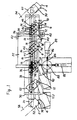
- Fig. 1 illustrates an apparatus for intermittently and successively feeding plastic bags 2 into a plurality of plastic bag processing stations according to the invention.
- the plastic bag 2 has a rectangular shape including an open end 4.
- the processing stations comprise a plastic bag corner cut station 6, a plastic bag opening station 8, a plastic bag heat sealing station 10 and a plastic bag cooling station 12, which are spaced from each other along the feeding passage of plastic bag 2 at a distance.
- the apparatus is arranged to intermittently and successively feed the plastic bags 2 into the corner cut station 6, the opening station 8, the heat sealing station 10 and the cooling station 12 in such a manner that the plastic bags 2 are inclined at an angle of 45 ° with respect to the feeding direction thereof and the open ends 4 comprise the trailing ends of the plastic bags 2 in the feeding direction thereof.
- the apparatus cootprises movable elongated member means extending parallel to the feeding direction of plastic bag 2 and fixed elongated member means extending parallel to the feeding direction of plastic bag 2 and d isposed side by side with the movable elongated member.
- the movable elongated member means comprises two movable lower beams 14 each including top surface, the fixed elongated member means comprising two fixed lower beams 16 each including top surface.
- the movable and fixed lower beams 14 and 16 are disposed side by side and alternately with each other, the top surfaces of the movable and fixed lower beams 14 and 16 being flush with each other.
- the plastic bags 2 are held on the top surfaces of the movable or fixed lower beams 14 and 16, as described later.
- the apparatus further comprises drive means connected to the movable lower beams 14.
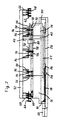
- the drive means includes a screw rod 18 extending parallel to the movable lower beams 14 and connected to a servo motor 20, as shown in Fig. 2.
- the movable lower beams 14 are fixedly mounted on a base 22 including a nut member 24 which is threadedly engaged with the screw rod 18.
- the base 22 is mounted on and supported by carriages 26 which are fitted onto and engaged with guide rails 28 for linearly movement, as shown in Fig. 3.
- the guide rails 28 extend parallel to the movable lower beams 14 and the screw rod 18.
- the screw rod 18 is rotated and then reversely rotated by the servo motor 20 so that the movable lower beams 14 and the base 22 are reciprocatingly moved in the longitudinal direction of the movable lower beams 14 along the guide rails 28 by the screw rod 18 and the nut member 24 at a stroke corresponding to the distance between the processing stations 6 to 12.
- the fixed lower beams 16 are fixedly mounted at opposite ends on supports 30.
- the movable elongated member means includes plastic bag holding means for holding and releasing the plastic bags 2.
- the fixed elongated member means also includes plastic bag holding means for holding and releasing the plastic bags 2.
- the apparatus further comprises activating means for activating the holding means of the movable and fixed elongated member means.
- the movable elongated member means further includes a movable upper beam 32 disposed above and extending parallel to the movable lower beams 14.
- the holding means comprises a plurality of clamp pads 34.
- the movable upper beam 32 includes three holders 36 for clamp pads 34 mounted thereon, two pairs of the clamp pads 34 being positioned at each holder 36.
- One of the pairs of clamp pads 34 are spaced from each other in the feeding direction of plastic bag 2 and opposed to one of the top surfaces of the movable lower beams 14, the other pair of clamp pads 34 being spaced from each other in the feeding direction of plastic bag 2 and opposed to the other top surface of the movable lower beam 14.
- the holders 36 are spaced from each other at a distance which corresponds to the distance between the processing stations 6 to 12 in the feeding direction of the plastic bag, two pairs of clamp pads 34 being carried by each holder 36.
- the activating means comprises a plurality of air or hydraulic cylinders 38, two pairs of which are mounted on each holder 36 and connected to the pairs of clamp pads 34 for moving the clamp pads 34 downward toward the top surfaces of the movable lower beams 14 to clamp and hold the plastic bag 2 between the clamp pads 34 and the top surfaces.
- the movable upper beam 32 is mounted on and supported by a cross member 40 the opposite ends of which are mounted on pillars 42.
- the pillars 42 are fixedly mounted on the base 22 so that the clamp pads 34, the holders 36 and the movable upper beam 32 are moved integrally with the movable lower beams 14 and the base 22.
- the holding means comprises a plurality of suction holes 44 formed in the top surfaces of the fixed lower beams 16, two pairs of the suction holes 44 being positioned at each processing station 6 to 12, as shown in Fig. 4.
- the activating means comprises vacuum means such as a vacuum blower not shown.
- the vacuum blower is connected by means of a switch valve to flow paths formed in the fixed lower beams 16 and communicated with the suction holes 44.
- the switch valve can be actuated for making the suction holes 44 vacuous to thereby suctionally hold the plastic bags 2.
- the holders 36 include a plurality of pusher pads 46, two pairs of pusher pads 46 being carried by each holder 36.
- the holders 36 include a plurality of pusher pads 46, two pairs of pusher pads 46 being carried by each holder 36.
- one of the pairs of pusher pads 46 are spaced from each other in the feeding direction of plastic bag 2 and opposed to one of the top surfaces of the fixed lower beams 16 at positions corresponding to the suction holes 44 therein, the other pair of pusher pads 46 being spaced from each other in the feeding direction of plastic bag 2 and opposed to the other top surface of the fixed lower beam 16 at positions corresponding to the suction holes 44 therein.
- the holders 36 further include a plurality of air or hydraulic cylinders 48, two pairs of which are mounted on each holder 36 and connected to the pairs of pusher pads 46 for moving the pusher pads 46 downward toward the top surfaces of the fixed lower beams 16 to push downward the plastic bag 2 toward the suction holes 44 in the fixed lower beams 16.
- the vacuum blower may be connected only to the flow path formed in one of the fixed lower beams 16, which is disposed between the movable lower beams 14, for making the suction holes 44 vacuous to suctionally hold small plastic bags.
- the pusher pads 46 opposed to the top surface of the other fixed lower beam 16 which is disposed on the outside of the movable lower beams 14 the pusher pads 46 and the cylinders 48 may be removed from the holders 36.
- the apparatus further comprises plastic bag supply and discharge stations 50 and 52 positioned at the opposite ends of the movable and fixed lower beams 14 and 16 in the longitudinal direction thereof.
- a conveyor 54 is provided for intermittently and successively feeding the plastic bags 2 one by one into the supply station 50.
- a conveyor 56 is provided for discharging the plastic bags 2 from the discharge station 52.
- the apparatus includes first delivery means comprising a plurality of suction members 58 for holding the plastic bag 2 at the supply station 50.
- the apparatus further includes second delivery means comprising a plurality of suction members 60 for holding the plastic bag 2 at the last processing station or the cooling station 12.
- the suction members 58 and 60 are mounted on and carried by holders 62 and 64 at positions corresponding to the suction holes 44 in the fixed lower beams 16.
- Air or hydraulic cylinders 66 and 68 are mounted on the movable upper beam 32 and connected to the holders 62 and 64 so that the suction members 58 and 60 are moved integrally with the movable lower and upper beams 14 and 32, for moving the holders 62 and 64 downward toward the plastic bags 2.
- the holders 62 and 64 are spaced from the holder 36 for the clamp pads 34 at a distance which corresponds to the distance between the processing stations 6 to 12 and the stroke at which the movable lower beams 14 are reciprocatingly moved.
- the cylinders 66 and 68 can move the holders 62 and 64 downward toward the plastic bags 2.
- the vacuum blower is connected to the suction members 58 and 60 by means of switch valves. The switch valve can be actuated for making the suction members 58 and 60 vacuous to suctionally hold the plastic bags 2 at the supply station 50 and the cooling station 12.
- the conveyor 54 is inclined at an angle of 45 ° with respect to the movable and fixed lower beams 14 and 16 in the supply station 50, to intermittently and successively feed the plastic bags 2 into the processing stations 6 to 12 so that the plastic bags 2 are inclined at an angle of 45 ° with respect to the feeding direction thereof and the open ends 4 comprise the trailing ends of the plastic bags 2 in the feeding direction thereof.
- the conveyor 56 is also inclined at an angle of 45 ° with respect to the movable and fixed lower beams 14 and 16 .
- a cutter or knife 70 is disposed at the corner cutting station 6 and mounted on a bracket 72.
- a receiving member 74 is disposed and fixed at the corner cutting station 6.
- the bracket 72 is mounted on the cross member 40 so that the cutter 70 cooperates with the receiving member 74 to obliquely cut the plastic bag 2 at one corner of the plastic bag 2 when the movable lower beams 14 are reversely moved, as described later.
- the opening device includes upper and lower suction members 76 opposed to each other and mounted on upper and lower arms 78.
- Air or hydraulic cylinders 80 are connected to the upper and lower arms 78 for moving the upper and lower arms 78 downward and upward toward each other to clamp the plastic bag 2 between the upper and lower suction members 76.
- the vacuum means such as the vacuum blower is connected to the upper and lower suction members 76 by means of a switch valve.
- the switch valve can be actuated for making the upper and lower suction members 76 vacuous to suctionally hold the plastic bag 2.
- the cylinders 80 then move the upper and lower arms 78 upward and downward for opening the open end 4 of the plastic bag 2 at the opening station 8.
- the cylinders 80 are mounted on the pillar 42 so that the opening device is moved integrally with the movable lower and upper beams 14 and 32 to intermittently feed the plastic bag 2 with the open end 4 opened into the heat sealing station 10.
- a spout feeder 82 and pickup fingers 84 are disposed at the heat sealing station 10.
- the spout feeder 82 intermittently and successively feeds spouts 86 one by one.
- the pickup fingers 84 grasp the spout 86 fed by the spout feeder 82.
- the pickup fingers 84 are then driven for rotation counterclockwise about an axis 88 to feed the spout 86 to a pre-heating device 89 from the spout feeder 82.
- the pre-heating device includes upper and lower heaters opposed to each other and clamps the spout 86 between the upper and lower heaters for pre-heating the spout 86.
- the pickup fingers 84 are then again driven for rotation counter clockwise about the axis 88 so that the pickup fingers 84 are rotationally moved with timed relation to the plastic bag 2 in the feeding direction of the plastic bag 2 and toward the open end 4 of the plastic bag 2 to insert the spout 86 into the cut corner of the open end 4 at the heat sealing station 10.
- a heat sealing device 90 is disposed at the heat sealing station 10.
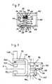
- the heat sealing device 90 includes upper and lower heaters 92H and 92L opposed to each other and mounted on upper and lower bars 94H and 94L, as shown in Fig. 5.
- the upper and lower bars 94H and 94L are fixedly mounted on guide members 96 which are fitted onto and engaged with a pillar 98 for linearly movement.
- the upper and lower bars 94H and 94L are connected to a lever 100 by means of links 102 respectively.
- the lever 100 is mounted on a bracket 104 for swingingly movement about a support 106, the bracket 104 being fixedly mounted on the pillar 98.
- An air or hydraulic cylinder 108 is mounted on a reactive member 110 and connected to the upper bar 94H.
- the reactive member 110 is mounted on and supported by the lower bar 94L so that the cylinder 108 cooperates with the reactive member 110, the links 102 and the lever 100 for moving the upper and lower bars 94H and 94L downward and upward toward each other to clamp the plastic bag 2 and the spout 86 between the upper and lower heaters 92H and 92L.
- the plastic bag 2 and the spout 86 are heated and pressurized by the upper and lower heaters 92H and 92L for heat sealing the plastic bag 2 and the spout 86 with each other to adhere the plastic bag 2 to the spout 86.
- a cooling device 112 is disposed at the cooling station 12.
- the cooling device 112 has the substantially same structure as the heat sealing device 90 except that it includes not the upper and lower heaters 92H and 92L but upper and lower coolers. Accordingly, an air or hydraulic cylinder cooperates with a reactive member, links and a lever for moving upper and lower bars downward and upward toward each other to clamp the plastic bag 2 and the spout 86 between the upper and lower coolers. The coolers and cool the plastic bag 2 and the spout 86.
- the cylinder 66 moves the holder 62 and the suction members 58 downward toward the plastic bag 2 at the supply station 50.
- the switching valve is actuated for making the suction members 58 vacuous to suctionally hold the plastic bag 2.
- the cylinder 66 then moves the holder 62 and the suction members 58 upward to lift the plastic bag 2.
- the screw rod 18 is then rotated by the servo motor 20 so that the movable lower and upper beams 14 and 32 and the base 22 are forwardly moved along the guide rails 28.
- the suction members 58 are moved integrally with the movable lower and upper beams 14 and 32 at a stroke corresponding to the distance between the supply station 50 and the corner cutting station 6 to feed the plastic bag 2 to the corner cutting station 6 from the supply station 50.
- the cylinder 66 moves the suction members 58 downward again at the corner cutting station 6 in the positions corresponding to the suction holes 44 in the fixed lower beams 16 to push the plastic bag 2 against the suction holes 44 in the fixed lower beams 16.
- the switching valve is actuated for making the suction holes 44 vacuous to thereby suctionally hold the plastic bag 2.
- the switching valve is actuated to release the plastic bag 2 from the suction members 58.
- the cylinder 66 then moves the suction members 58 upward from the plastic bag 2.
- the plastic bag 2 is held by the suction holes 44 in the fixed lower beams 16 and released from the suction members 58.
- the screw rod 18 is then rotated by the servo motor 20 so that the movable lower and upper beams 14 and 32 are reversely and backwardly moved along the guide rails 28.
- the suction members 58 are moved integrally with the movable lower and upper beams 14 and 32 to the supply station 50.
- the cylinders 38 then moves the clamp pads 34 downward toward the top surfaces of the movable lower beams 14 to clamp and hold the plastic bag 2 between the clamp pads 34 and the top surfaces at the corner cutting station 6, when the cylinder 66 moves the suction members 58 downward again at the supply station 50 for suctionally holding the plastic bag 2 at the supply station 4.
- the switching valve is actuated for releasing the plastic bag 2 from the suction holes 44.
- the cylinder 66 moves the suction members 58 upward to lift the plastic bag 2 at the supply station 4.
- the plastic bags 2 are held by the clamp pads 34 and the suction members 58 of the movable lower and upper beams 14 and 32 and released from the suction holes 44 in the fixed lower beams 16.
- the movable lower and upper beams 14 and 32 are then forwardly moved.
- the clamp pads 34 are moved integrally with the movable lower and upper beams 14 and 32 to feed the plastic bags 2 to the opening station 8 from the corner cutting station 6 and to the corner cutting station 6 from the supply station 4.
- the cylinder 48 then moves the pusher pads 46 downward at the opening station 8 in the positions corresponding to the suction holes 44 in the fixed lower beams 16 to push the plastic bag 2 against the suction holes 44 in the fixed lower beams 16, when the cylinders 66 move the suction members 58 downward to push the plastic bag 2 against the suction holes 44 at the cutting station 6.
- the switching valves are actuated for making the suction holes 44 vacuous to thereby suctionally hold the plastic bag 2 at the corner cutting station 6 and the opening station 8 and releasing the plastic bag 2 from the suction members 58.
- the cylinder 38, 48 and 66 then moves the clamp pads 34, the pusher pads 46 and the suction members 58 upward from the plastic bag 2.
- the plastic bag 2 is held by the suction holes 44 in the fixed lower beams 16 and released from the clamp pads 34 and the suction members 58 of the movable lower and upper beams 14 and 32.
- the screw rod 18 is then rotated by the servo motor 20 so that the movable lower and upper beams 14 and 32 are reversely and backwardly moved along the guide rails 28.
- the cylinder 68 then moves the holder 64 and the suction members 60 downward toward the plastic bag 2 at the cooling station 12, when the the cylinder 66 moves the suction members 58 downward at the supply station 50 and the cylinders 38 move the clamp pads 34 toward the top surfaces of the movable lower beams 14 at the corner cutting station 6, the opening station 8 and the heat sealing station 10.
- the switching valve is actuated for making the suction members 60 vacuous to suctionally hold the plastic bag 2.
- the cylinders 66 and 68 then move the suction members 58 and 60 upward to lift the plastic bags 2 at the supply station 50 and the cooling station 12.
- the suction members 60 is moved integrally with the movable lower and upper beams 14 and 32 when the movable lower and upper beams 14 and 32 are forwardly moved, to feed the plastic bag 2 to the discharge station 52 from the cooling station 12.
- the switching valve is then actuated for releasing the plastic bag 2 from the suction members 60 at the discharge station 52.
- the plastic bag 2 is discharged from the discharge station 52 by the conveyor 56.
- the apparatus can therefore intermittently and successively feed the plastic bags 2 into the corner cutting station 6, the opening station 8, heat sealing station 10 and the cooling station 12.
- the apparatus also can successively and conveniently stop and hold the plastic bags 2 at the corner cutting station 6, the opening station 8, heat sealing station 10 and the cooling station 12. Accordingly, it can successively and obliquely cut the plastic bags 2 at the corner cutting station 6, and successively heat seal the plastic bags 2 and the spouts 86 with each other to adhere the plastic bags 2 to the spout 86 at the heat sealing station 10.
- the apparatus can be a miniaturized and simple structure to accomplish the intended purpose.
- the cutter 70 is moved integrally with the bracket 72 and the movable lower and upper beams 14 and 32 and travelled along the receiving member 74 at the corner cutting station 4.
- the cutter 70 can therefore cooperate with the receiving member 74 to obliquely cut the plastic bag 2 at one corner of the open end 4 of the plastic bag 2 when the movable lower and upper beams 14 and 32 are backwardly moved.
- the apparatus then feeds the plastic bag 2 to the opening station 8 from the corner cutting station 6.
- the opening device activates the upper and lower suction members 76 to suctionally hold and open the open end 4 of the plastic bag 2 at the opening station 8.
- the opening device is then moved integrally with the movable lower and upper beams 14 and 32 when the movable lower and upper beams 14 and 32 are forwardly moved along the guide rails 28, to intermittently feed the plastic bag 2 with the open end 4 opened into the heat sealing station 10.
- the pickup fingers 84 are rotationally moved with timed relation to the plastic bag 2 in the feeding direction of the plastic bag 2 and toward the open end 4 of the plastic bag 2 to insert the spout 86 into the cut corner of the open end 4, as shown in Fig. 6, at the heat sealing station 10.
- the upper and lower suction members 76 then release the plastic bag 2.
- the heat sealing device 90 heat seals the plastic bag 2 and the spout 86 with each other to adhere the plastic bag 2 to the spout 86 at the heat sealing station 10.
- the apparatus then feeds the plastic bag 2 to the cooling station 12 from the heat sealing station 10.
- the cooling device 112 cools the plastic bag 2 and the spout 96 at the cooling station 12.
- the apparatus then feed the plastic bag 2 to the discharge station 52 from the cooling station 12.
- the conveyor 56 discharges the plastic bag 2 from the discharge station 52.
- the fixed elongated member means may further comprise fixed upper beam means disposed above the fixed lower beams 16.
- the holding means may comprise a plurality of clamp pads opposed to the top surfaces of the fixed lower beams 16.
- the activating means may comprise drive means mounted on the fixed upper beam means and connected to the clamp pads for moving the clamp pads downward toward the top surfaces to clamp and hold the plastic bags 2 between the clamp pads and the top surfaces.
- the holding means may comprise a plurality of suction holes formed in the top surfaces of the movable lower beams 14.
- the activating means may comprise vacuum means connected to the suction holes for making the suction holes vacuous to thereby suctionally hold the plastic bags 2.
- a ultrasonic wave sealing device may be substituted for the heat sealing device 90 and disposed at a ultrasonic wave station corresponding to the heat sealing station 10, for ultrasonic wave sealing the plastic bag 2 and the spout 86 to adhere the plastic bag 2 to the spout 86. In the case, it is not required to cool the plastic bag 2 and spout 86.
- the cooling station 12 and the cooling device device 112 can be removed.
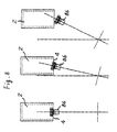
- the apparatus may be arranged to intermittently and successively feed the plastic bags 2 into the corner cut station 6, the opening station 8 and the heat sealing or ultrasonic wave sealing station 10 in such a manner that the plastic bags 2 are inclined at an angle with respect to the feeding direction thereof and the open ends 4 comprise not the trailing ends but the leading ends of the plastic bags 2 in the feeding direction thereof, as shown in Fig. 7.
- the spout 86 may be previously moved by the pickup fingers into a position corresponding to the cut corner of the open end 4 before the plastic bag 2 reaches the heat sealing or ultrasonic wave sealing station 10, to insert the spout 86 into the cut corner through the open end 4 when the plastic bag 2 reaches the heat sealing or ultrasonic wave sealing station 10.
- the apparatus may be arranged to intermittently and successively feed the plastic bags 2 into the opening station 8 and the heat sealing or ultrasonic wave sealing station 10 in such a manner that the plastic bags 2 extend perpendicularly to the feeding direction thereof, as shown in Fig. 8.
- the pickup fingers 84 may be rotationally moved with timed relation to the plastic bag 2 in the feeding direction of the plastic bag 2 and toward the open end 4 of the plastic bag 2 to insert the spout 86 into the the open end 4 of the plastic bag 2 at the heat sealing or ultrasonic wave sealing station 10.
- the pickup fingers are mounted on and moved integrally with the movable elongated member means and linearly moved toward the open end 4 of the plastic bag 2 to thereby insert the spout 86 into the open end 4 of the plastic bag 2 at the heat sealing or ultrasonic wave sealing station 10.
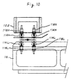
- the movable upper beam 32 is disposed above the movable lower beams 14 and the fixed lower beams 16.
- the holding means comprises a plurality of first upper and lower pairs of clamp pads 114H and 114L opposed to each other and disposed between the movable upper and lower beams 32 and 14.
- the holding means further comprises a plurality of second upper and lower pairs of clamp pads 116H and 116L opposed to each other and disposed between the movable upper beams 32 and the fixed lower beam means 16.
- the activating means includes a plurality of first upper and lower pairs of drive means comprising air or hydraulic cylinders 118H and 118L.
- the upper and lower cylinders 118H and 118L are mounted on the movable upper and lower beams 32 and 14 and connected to the first upper and lower clamp pads 114H and 114L respectively for moving the f irst upper and lower clamp pads 114H and 114L downward and upward toward each other to clamp and hold the plastic bags 2 between the first upper and lower clamp pads 114H and 114L.
- the activating means further includes a plurality of second upper and lower pairs of drive means comprising air or hydraulic cylinders 120H and 120L.
- the upper and lower cylinders 120H and 120L are mounted on the movable upper beam 32 and the fixed lower beams 16 and connected to the second upper and lower clamp pads 116H and 1161 respectively for moving the second upper and lower clamp pads 116H and 1161 downward and upward toward each other to clamp and hold the plastic bags 2 between the second upper and lower clamp pads 116H and 1161, and then moving the second upper clamp pads 116H upward from the second lower clamp pads 116L.
- the second lower clamp pads 116L comprise vacuum pads, vacuum means being connected to the vacuum pads 116L for making the vacuum pads 116L vacuous to suctionally hold the material when and after moving the second upper clamp pads 116H upward from the second lower clamp pads 116L.
- the plastic bags 2 can be held by the first upper and lower clamp pads 114H and 114L of the movable upper and lower beams 32 and 14 and released from the second lower clamp pads 116L of the fixed lower beam 16 when the movable upper and lower beams 32 and 14 is forwardly moved, to intermittently and successively feed the plastic bags 2.
- the plastic bags 2 can be held by the second lower clamp pads 116L of the fixed lower beam 16 and released from the first upper and lower clamp pads 114H and 114L of the movable upper and lower beams 32 and 14 when the movable upper and lower beams 32 and 14 is reversely and backwardly moved, to successively and conveniently hold the plastic bags 2.
- the embodiment can clamp and hold the plastic bags 2 between the first upper and lower clamp pads 114H and 114L or the second upper and lower clamp pads 116H and 116L, without engaging the plastic bag 2 with the movable or fixed upper and lower beams. It is convenient to insert the spout 86 including the elongated conduit 113 into the open end of the plastic bag 2 shown in Fig. 9, and heat seal or ultrasonic wave seal the plastic bag 2 and the spout 86 with each other.
Landscapes
- Engineering & Computer Science (AREA)
- Mechanical Engineering (AREA)
- Making Paper Articles (AREA)
Description
- The invention relates to an apparatus for intermittently and successively feeding sheet materials such as plastic bags into a plurality of sheet material processing stations which are spaced from each other along the feeding passage of sheet material.
- There has been recently commercially available a plastic bag including a spout which is made of plastic material and adapted to direct a liquid such as a drink out of the plastic bag. The plastic bag has a certain shape including an open end which is obliquely cut at one corner thereof. The spout is inserted into the cut corner of the open end, the plastic bag and the spout being heat sealed with each other to adhere the plastic bag to the spout. The plastic bag and the spout may be ultrasonic wave sealed with each other to adhere the plastic bag to the spout. The liquid is then poured and charged into the plastic bag from the open end thereof, in a liquid charging apparatus.
- Under the circumstances, it has been intended to intermittently and successively feed plastic bags into a plastic bag corner cutting station, and successively and obliquely cut the plastic bags at one corners of the open ends of the plastic bags at the corner cutting station, in an apparatus. It has been also intended to then intermittently and successively feed the plastic bags into a plastic bag heat sealing or ultrasonic wave sealing station, and successively heat seal or ultrasonic wave seal the plastic bags and the spouts with each other at the sealing station, in the apparatus. However, in this case, it is required not only to intermittently and successively feed plastic bags into the corner cutting station and the sealing station, but also to successively and conveniently stop and hold the plastic bags at the corner cutting station and the sealing station. It therefore has a problem that the apparatus has to be large-sized and complicated.
- GB-A-2 010 784 already discloses an apparatus for use in handling signatures, which comprises a plurality of operating stations, a saddle extending between the operating stations, a carriage, means for supporting the carriage for movement along the saddle, and drive means for moving the carriage along the saddle. First clamp means are connected with the carriage for gripping a first signature at a first operating station while the carriage, first clamp means and first signature are moving along the saddle at a first speed. Second clamp means are connected with the carriage for gripping a second signature at a second operating station while the carriage and first signature are stationary. First actuator means effect operation of the first clamp means to grip the first signature while the carriage, first and second clamp means and first signature are moving along the saddle at the first speed, and second actuator means effect operation of the second clamp means to grip the second signature while the carriage and second signature are stationary. When the carriage arrives at the end of the forward stroke, both of the signatures are released. After that, the carriage returns to its initial position for gripping and conveying the second and a third signature. This apparatus, however, only comprises means for conveying the signatures between the operating stations, but no means for handling the signatures in the respective operating stations
- It is therefore an object of the invention to provide a novel and improved apparatus for intermittently and successively feeding sheet materials such as plastic bags into a plurality of sheet material processing stations which are spaced from each other along the feeding passage of the sheet material, and for successively and conveniently stop and hold the sheet materials at the sheet material processing stations.
- Another object of the invention is to provide an apparatus which has a miniaturized and simple structure to accomplish the intended purpose.
- This object according to the invention is solved by an apparatus comprising the features of claim 1. Preferred embodiments of this apparatus are defined in the subclaims
- The apparatus comprises movable elongated member means extending parallel to the feeding direction of sheet material. The movable elongated member means includes sheet material holding means for holding and releasing the sheet materials. The apparatus further comprises fixed elongated member means extending parallel to the feeding direction of sheet material and disposed side by side with the movable elongated member means. The fixed elongated member means also includes sheet material holding means for holding and releasing the sheet materials.
- Drive means is connected to the movable elongated member means, the movable elongated member means being reciprocatingly moved in the longitudinal direction thereof by the drive means at a stroke corresponding to the distance between the processing stations. Activating means is provided for activating the holding means of the movable and fixed elongated member means so that the sheet materials are held by the holding means of the movable elongated member means and released from the holding means of the fixed elongated member means when the movable elongated member means is forwardly moved. The sheet materials are held by the holding means of the fixed elongated member means and released from the holding means of the movable member means when the movable member means is reversely and backwardly moved.
- The movable elongated member means may comprise a plurality of movable elongated members. The fixed elongated member means may comprise a plurality of fixed elongated members, the movable and fixed elongated members being disposed side by side and alternately with each other.
- In a preferred embodiment, the movable and fixed elongated member means comprise movable and fixed lower beam means each including top surface means, the top surface means of the movable and fixed lower beam means being flush with each other. The sheet materials are held on the top surface means of the movable or fixed lower beam means.
- At least one of the movable and fixed elongated member means may further comprise movable or fixed upper beam means disposed above the movable or fixed lower beam means. The holding means may comprise a plurality of clamp pads opposed to the top surface means of the movable or fixed lower beam means. The activating means may comprise drive means mounted on the movable or fixed upper beam means and connected to the clamp pads for moving the clamp pads downward toward the top surface means to clamp and hold the sheet materials between the clamp pads and the top surface means.
- The holding means may comprise a plurality of suction holes formed in the top surface means of at least one of the movable and fixed lower beam means. The activating means may comprise vacuum means connected to the suction holes for making the suction holes vacuous to thereby suctionally hold the sheet materials.
- In other embodiment, the movable elongated member means comprises movable upper and lower beam means. The fixed elongated member means comprises fixed lower beam means. The movable upper beam means is disposed above the movable lower beam means and the fixed lower beam means. The holding means comprises a plurality of first upper and lower pairs of clamp pads opposed to each other and disposed between the movable upper and lower beam means, and a plurality of second upper and lower pairs of clamp pads opposed to each other and disposed between the movable upper beam means and the fixed lower beam means. The activating means comprises a plurality of first upper and lower pairs of drive means and a plurality of second upper and lower pairs of drive means. The first upper and lower drive means are mounted on the movable upper and lower beam means and connected to the first upper and lower clamp pads respectively for moving the first upper and lower clamp pads downward and upward toward each other to clamp and hold the sheet materials between the first upper and lower clamp pads. The second upper and lower drive means are mounted on the movable upper beam means and the fixed lower beam means and connected to the second upper and lower clamp pads respectively for moving the second upper and lower clamp pads downward and upward toward each other to clamp and hold the sheet materials between the second upper and lower clamp pads, and then moving the second upper clamp pads upward from the second lower clamp pads. The second lower clamp pads comprise vacuum pads, vacuum means being connected to the vacuum pads for making the vacuum pads vacuous to suctionally hold the sheet material when and after moving the second upper clamp pads upward from the second lower clamp pads.
- The movable upper beam means may be disposed above the movable lower beam means. The fixed elongated member means may comprise fixed upper and lower beam means. The fixed upper beam means is disposed above the fixed lower beam means. The second upper and lower clamp pads may be disposed between the fixed upper and lower beam means. The second upper and lower drive means may be mounted on the fixed upper and lower beam means and connected to the second upper and lower clamp pads respectively for moving the second upper and lower pads downward and upward toward each other to clamp and hold the sheet materials between the second upper and lower clamp pads.
- The apparatus may further comprise sheet material supply and discharge stations positioned at the opposite ends of the movable and fixed elongated member means in the longitudinal direction thereof, first delivery means for holding the sheet material at the supply station, and second delivery means for holding the sheet material at the last processing station. The first and second delivery means are mounted on and moved integrally with the movable elongated member means for intermittently and successively feeding the sheet materials into the first processing station from the supply station and into the discharge station from the last processing station.
- The sheet material may comprise a plastic bag which has a certain shape including an open end. The processing stations may comprise a plastic bag corner cut station, a plastic bag opening station and a plastic bag heat sealing or ultrasonic wave sealing station. The apparatus may be arranged to intermittently and successively feed the plastic bags into the corner cut station, the opening station and the heat sealing or ultrasonic wave sealing station in such a manner that the plastic bags are inclined at an angle with respect to the feeding direction thereof and the open ends comprise the trailing ends of the plastic bags in the feeding direction thereof. The apparatus may further comprise a cutter disposed at the corner cut station for obliquely cutting the plastic bag at one corner of the open end of the plastic bag, an opening device for opening the open end of the plastic bag at the opening station, and pickup fingers adapted to grasp an accessary such as a spout for inserting it into the cut corner of the open end. The opening device is mounted on and moved integrally with the movable elongated member means to intermittently feed the plastic bag with the open end opened into the heat sealing or ultrasonic wave sealing station. The pickup fingers are rotatingly moved with timed relation to the plastic bag in the feeding direction of the plastic bag and toward the open end of the plastic bag to insert the accessary into the cut corner of the open end at the heat sealing or ultrasonic wave station. The apparatus may further comprise a heat sealing or ultrasonic wave sealing device disposed at the heat sealing or ultrasonic wave sealing station for heat sealing or ultrasonic wave sealing the plastic bag and the accessary with each other to adhere the plastic bag to the accessary.
- The apparatus may be arranged to intermittently and successively feed the plastic bags into the corner cut station, the opening station and the heat sealing or ultrasonic wave sealing station in such a manner that the plastic bags are inclined at an angle with respect to the feeding direction thereof and the open ends comprise the leading ends of the plastic bags in the feeding direction thereof. The accessary may be previously moved by the pickup fingers into a position corresponding to the cut corner of the open end before the plastic bag reaches the heat sealing or ultrasonic wave sealing station, to insert the accessary into the cut corner through the open end when the plastic bag reaches the heat sealing or ultrasonic wave sealing station.
- The apparatus may be arranged to intermittently and successively feed the plastic bags into the opening station and the heat sealing or ultrasonic wave sealing station in such a manner that the plastic bags extend perpendicularly to the feeding direction thereof.
- The pickup fingers may be adapted to grasp an accessary such as a spout including an elongated conduit for inserting it into the open end of the plastic bag. The pickup fingers are mounted on and moved integrally with the movable elongated member means and linearly moved toward the open end of the plastic bag to thereby insert the accessary into the open end of the plastic bag at the heat sealing or ultrasonic wave sealing station.
-
- Fig. 1 is a plan view of a preferred embodiment of the invention.
- Fig. 2 is a side view of the apparatus in Fig. 1.
- Fig. 3 is cross sectional view of the apparatus in Fig. 1.
- Fig. 4 is a plan view of the movable and fixed lower beams in Fig. 1.
- Fig. 5 is a schematic view of the heat sealing device in Fig. 1.
- Fig. 6 is a schematic view of a spout inserted into the cut corner of the open end of a plastic bag in Fig. 1.
- Fig. 7 is a schematic view of other embodiment.
- Fig. 8 is a schematic view of other embodiment.
- Fig. 9 is a schematic view of other embodiment.
- Fig. 10 is a side view showing first upper and lower clamp pads of other embodiment.
- Fig. 11 is a side view showing second upper and lower clamp pads of the apparatus in Fig. 10.
- Fig. 12 is a cross sectional view of the apparatus in Figs. 10 and 11.
-
- Turning now to the drawings, Fig. 1 illustrates an apparatus for intermittently and successively feeding
plastic bags 2 into a plurality of plastic bag processing stations according to the invention. Theplastic bag 2 has a rectangular shape including anopen end 4. The processing stations comprise a plastic bag corner cutstation 6, a plastic bag opening station 8, a plastic bagheat sealing station 10 and a plasticbag cooling station 12, which are spaced from each other along the feeding passage ofplastic bag 2 at a distance. The apparatus is arranged to intermittently and successively feed theplastic bags 2 into the corner cutstation 6, the opening station 8, theheat sealing station 10 and thecooling station 12 in such a manner that theplastic bags 2 are inclined at an angle of 45 ° with respect to the feeding direction thereof and the open ends 4 comprise the trailing ends of theplastic bags 2 in the feeding direction thereof. - The apparatus cootprises movable elongated member means extending parallel to the feeding direction of
plastic bag 2 and fixed elongated member means extending parallel to the feeding direction ofplastic bag 2 and d isposed side by side with the movable elongated member. The movable elongated member means comprises two movablelower beams 14 each including top surface, the fixed elongated member means comprising two fixedlower beams 16 each including top surface. The movable and fixedlower beams lower beams plastic bags 2 are held on the top surfaces of the movable or fixedlower beams - The apparatus further comprises drive means connected to the movable lower beams 14. The drive means includes a
screw rod 18 extending parallel to the movablelower beams 14 and connected to aservo motor 20, as shown in Fig. 2. The movablelower beams 14 are fixedly mounted on a base 22 including anut member 24 which is threadedly engaged with thescrew rod 18. Thebase 22 is mounted on and supported bycarriages 26 which are fitted onto and engaged withguide rails 28 for linearly movement, as shown in Fig. 3. The guide rails 28 extend parallel to the movablelower beams 14 and thescrew rod 18. Thescrew rod 18 is rotated and then reversely rotated by theservo motor 20 so that the movablelower beams 14 and the base 22 are reciprocatingly moved in the longitudinal direction of the movablelower beams 14 along the guide rails 28 by thescrew rod 18 and thenut member 24 at a stroke corresponding to the distance between theprocessing stations 6 to 12. The fixedlower beams 16 are fixedly mounted at opposite ends on supports 30. - The movable elongated member means includes plastic bag holding means for holding and releasing the
plastic bags 2. The fixed elongated member means also includes plastic bag holding means for holding and releasing theplastic bags 2. In this connection, the apparatus further comprises activating means for activating the holding means of the movable and fixed elongated member means. - In the embodiment, the movable elongated member means further includes a movable
upper beam 32 disposed above and extending parallel to the movable lower beams 14. The holding means comprises a plurality ofclamp pads 34. The movableupper beam 32 includes threeholders 36 forclamp pads 34 mounted thereon, two pairs of theclamp pads 34 being positioned at eachholder 36. One of the pairs ofclamp pads 34 are spaced from each other in the feeding direction ofplastic bag 2 and opposed to one of the top surfaces of the movablelower beams 14, the other pair ofclamp pads 34 being spaced from each other in the feeding direction ofplastic bag 2 and opposed to the other top surface of the movablelower beam 14. Theholders 36 are spaced from each other at a distance which corresponds to the distance between theprocessing stations 6 to 12 in the feeding direction of the plastic bag, two pairs ofclamp pads 34 being carried by eachholder 36. The activating means comprises a plurality of air orhydraulic cylinders 38, two pairs of which are mounted on eachholder 36 and connected to the pairs ofclamp pads 34 for moving theclamp pads 34 downward toward the top surfaces of the movablelower beams 14 to clamp and hold theplastic bag 2 between theclamp pads 34 and the top surfaces. The movableupper beam 32 is mounted on and supported by across member 40 the opposite ends of which are mounted onpillars 42. Thepillars 42 are fixedly mounted on the base 22 so that theclamp pads 34, theholders 36 and the movableupper beam 32 are moved integrally with the movablelower beams 14 and thebase 22. - As to the fixed
lower beams 16, the holding means comprises a plurality of suction holes 44 formed in the top surfaces of the fixedlower beams 16, two pairs of the suction holes 44 being positioned at eachprocessing station 6 to 12, as shown in Fig. 4. At eachprocessing station 6 to 12, one of the pairs of suction holes 44 are spaced from each other in the feeding direction ofplastic bag 2 and formed in one of the top surfaces of the fixedlower beams 16, the other pair of suction holes 44 being spaced from each other in the feeding direction ofplastic bag 2 and formed in the other top surface of the fixedlower beam 16. The activating means comprises vacuum means such as a vacuum blower not shown. The vacuum blower is connected by means of a switch valve to flow paths formed in the fixedlower beams 16 and communicated with the suction holes 44. The switch valve can be actuated for making the suction holes 44 vacuous to thereby suctionally hold theplastic bags 2. - In addition, the
holders 36 include a plurality ofpusher pads 46, two pairs ofpusher pads 46 being carried by eachholder 36. On eachholder 36, one of the pairs ofpusher pads 46 are spaced from each other in the feeding direction ofplastic bag 2 and opposed to one of the top surfaces of the fixedlower beams 16 at positions corresponding to the suction holes 44 therein, the other pair ofpusher pads 46 being spaced from each other in the feeding direction ofplastic bag 2 and opposed to the other top surface of the fixedlower beam 16 at positions corresponding to the suction holes 44 therein. Theholders 36 further include a plurality of air orhydraulic cylinders 48, two pairs of which are mounted on eachholder 36 and connected to the pairs ofpusher pads 46 for moving thepusher pads 46 downward toward the top surfaces of the fixedlower beams 16 to push downward theplastic bag 2 toward the suction holes 44 in the fixed lower beams 16. - By the way, the vacuum blower may be connected only to the flow path formed in one of the fixed
lower beams 16, which is disposed between the movablelower beams 14, for making the suction holes 44 vacuous to suctionally hold small plastic bags. In the case, as to thepusher pads 46 opposed to the top surface of the other fixedlower beam 16 which is disposed on the outside of the movablelower beams 14, thepusher pads 46 and thecylinders 48 may be removed from theholders 36. - The apparatus further comprises plastic bag supply and
discharge stations 50 and 52 positioned at the opposite ends of the movable and fixedlower beams conveyor 54 is provided for intermittently and successively feeding theplastic bags 2 one by one into thesupply station 50. Aconveyor 56 is provided for discharging theplastic bags 2 from the discharge station 52. In addition, the apparatus includes first delivery means comprising a plurality ofsuction members 58 for holding theplastic bag 2 at thesupply station 50. The apparatus further includes second delivery means comprising a plurality ofsuction members 60 for holding theplastic bag 2 at the last processing station or thecooling station 12. Thesuction members holders hydraulic cylinders upper beam 32 and connected to theholders suction members upper beams holders plastic bags 2. Theholders holder 36 for theclamp pads 34 at a distance which corresponds to the distance between theprocessing stations 6 to 12 and the stroke at which the movablelower beams 14 are reciprocatingly moved. Thecylinders holders plastic bags 2. In addition, the vacuum blower is connected to thesuction members suction members plastic bags 2 at thesupply station 50 and thecooling station 12. - The
conveyor 54 is inclined at an angle of 45 ° with respect to the movable and fixedlower beams supply station 50, to intermittently and successively feed theplastic bags 2 into theprocessing stations 6 to 12 so that theplastic bags 2 are inclined at an angle of 45 ° with respect to the feeding direction thereof and the open ends 4 comprise the trailing ends of theplastic bags 2 in the feeding direction thereof. Theconveyor 56 is also inclined at an angle of 45 ° with respect to the movable and fixedlower beams - A cutter or
knife 70 is disposed at thecorner cutting station 6 and mounted on abracket 72. A receiving member 74 is disposed and fixed at thecorner cutting station 6. Thebracket 72 is mounted on thecross member 40 so that thecutter 70 cooperates with the receiving member 74 to obliquely cut theplastic bag 2 at one corner of theplastic bag 2 when the movablelower beams 14 are reversely moved, as described later. - An opening device is disposed at the opening station 8. The opening device includes upper and
lower suction members 76 opposed to each other and mounted on upper andlower arms 78. Air orhydraulic cylinders 80 are connected to the upper andlower arms 78 for moving the upper andlower arms 78 downward and upward toward each other to clamp theplastic bag 2 between the upper andlower suction members 76. The vacuum means such as the vacuum blower is connected to the upper andlower suction members 76 by means of a switch valve. The switch valve can be actuated for making the upper andlower suction members 76 vacuous to suctionally hold theplastic bag 2. Thecylinders 80 then move the upper andlower arms 78 upward and downward for opening theopen end 4 of theplastic bag 2 at the opening station 8. Thecylinders 80 are mounted on thepillar 42 so that the opening device is moved integrally with the movable lower andupper beams plastic bag 2 with theopen end 4 opened into theheat sealing station 10. - A
spout feeder 82 andpickup fingers 84 are disposed at theheat sealing station 10. Thespout feeder 82 intermittently and successively feedsspouts 86 one by one. Thepickup fingers 84 grasp thespout 86 fed by thespout feeder 82. Thepickup fingers 84 are then driven for rotation counterclockwise about anaxis 88 to feed thespout 86 to apre-heating device 89 from thespout feeder 82. The pre-heating device includes upper and lower heaters opposed to each other and clamps thespout 86 between the upper and lower heaters for pre-heating thespout 86. Thepickup fingers 84 are then again driven for rotation counter clockwise about theaxis 88 so that thepickup fingers 84 are rotationally moved with timed relation to theplastic bag 2 in the feeding direction of theplastic bag 2 and toward theopen end 4 of theplastic bag 2 to insert thespout 86 into the cut corner of theopen end 4 at theheat sealing station 10. - A
heat sealing device 90 is disposed at theheat sealing station 10. Theheat sealing device 90 includes upper andlower heaters lower bars lower bars guide members 96 which are fitted onto and engaged with apillar 98 for linearly movement. The upper andlower bars lever 100 by means oflinks 102 respectively. Thelever 100 is mounted on abracket 104 for swingingly movement about asupport 106, thebracket 104 being fixedly mounted on thepillar 98. An air orhydraulic cylinder 108 is mounted on areactive member 110 and connected to theupper bar 94H. Thereactive member 110 is mounted on and supported by thelower bar 94L so that thecylinder 108 cooperates with thereactive member 110, thelinks 102 and thelever 100 for moving the upper andlower bars plastic bag 2 and thespout 86 between the upper andlower heaters plastic bag 2 and thespout 86 are heated and pressurized by the upper andlower heaters plastic bag 2 and thespout 86 with each other to adhere theplastic bag 2 to thespout 86. - A
cooling device 112 is disposed at thecooling station 12. Thecooling device 112 has the substantially same structure as theheat sealing device 90 except that it includes not the upper andlower heaters plastic bag 2 and thespout 86 between the upper and lower coolers. The coolers and cool theplastic bag 2 and thespout 86. - In the apparatus, in the first place, the
cylinder 66 moves theholder 62 and thesuction members 58 downward toward theplastic bag 2 at thesupply station 50. The switching valve is actuated for making thesuction members 58 vacuous to suctionally hold theplastic bag 2. Thecylinder 66 then moves theholder 62 and thesuction members 58 upward to lift theplastic bag 2. - The
screw rod 18 is then rotated by theservo motor 20 so that the movable lower andupper beams suction members 58 are moved integrally with the movable lower andupper beams supply station 50 and thecorner cutting station 6 to feed theplastic bag 2 to thecorner cutting station 6 from thesupply station 50. - The
cylinder 66 moves thesuction members 58 downward again at thecorner cutting station 6 in the positions corresponding to the suction holes 44 in the fixedlower beams 16 to push theplastic bag 2 against the suction holes 44 in the fixed lower beams 16. The switching valve is actuated for making the suction holes 44 vacuous to thereby suctionally hold theplastic bag 2. As to thesuction members 58, the switching valve is actuated to release theplastic bag 2 from thesuction members 58. Thecylinder 66 then moves thesuction members 58 upward from theplastic bag 2. - Accordingly, the
plastic bag 2 is held by the suction holes 44 in the fixedlower beams 16 and released from thesuction members 58. Thescrew rod 18 is then rotated by theservo motor 20 so that the movable lower andupper beams suction members 58 are moved integrally with the movable lower andupper beams supply station 50. - The
cylinders 38 then moves theclamp pads 34 downward toward the top surfaces of the movablelower beams 14 to clamp and hold theplastic bag 2 between theclamp pads 34 and the top surfaces at thecorner cutting station 6, when thecylinder 66 moves thesuction members 58 downward again at thesupply station 50 for suctionally holding theplastic bag 2 at thesupply station 4. As to the suction holes 44 in the fixedlower beams 16, the switching valve is actuated for releasing theplastic bag 2 from the suction holes 44. Thecylinder 66 moves thesuction members 58 upward to lift theplastic bag 2 at thesupply station 4. - Accordingly, the
plastic bags 2 are held by theclamp pads 34 and thesuction members 58 of the movable lower andupper beams upper beams clamp pads 34 are moved integrally with the movable lower andupper beams plastic bags 2 to the opening station 8 from thecorner cutting station 6 and to thecorner cutting station 6 from thesupply station 4. - The
cylinder 48 then moves thepusher pads 46 downward at the opening station 8 in the positions corresponding to the suction holes 44 in the fixedlower beams 16 to push theplastic bag 2 against the suction holes 44 in the fixedlower beams 16, when thecylinders 66 move thesuction members 58 downward to push theplastic bag 2 against the suction holes 44 at the cuttingstation 6. The switching valves are actuated for making the suction holes 44 vacuous to thereby suctionally hold theplastic bag 2 at thecorner cutting station 6 and the opening station 8 and releasing theplastic bag 2 from thesuction members 58. Thecylinder clamp pads 34, thepusher pads 46 and thesuction members 58 upward from theplastic bag 2. - Accordingly, the
plastic bag 2 is held by the suction holes 44 in the fixedlower beams 16 and released from theclamp pads 34 and thesuction members 58 of the movable lower andupper beams screw rod 18 is then rotated by theservo motor 20 so that the movable lower andupper beams - The
cylinder 68 then moves theholder 64 and thesuction members 60 downward toward theplastic bag 2 at thecooling station 12, when the thecylinder 66 moves thesuction members 58 downward at thesupply station 50 and thecylinders 38 move theclamp pads 34 toward the top surfaces of the movablelower beams 14 at thecorner cutting station 6, the opening station 8 and theheat sealing station 10. The switching valve is actuated for making thesuction members 60 vacuous to suctionally hold theplastic bag 2. Thecylinders suction members plastic bags 2 at thesupply station 50 and thecooling station 12. - The
suction members 60 is moved integrally with the movable lower andupper beams upper beams plastic bag 2 to the discharge station 52 from thecooling station 12. The switching valve is then actuated for releasing theplastic bag 2 from thesuction members 60 at the discharge station 52. Theplastic bag 2 is discharged from the discharge station 52 by theconveyor 56. - The apparatus can therefore intermittently and successively feed the
plastic bags 2 into thecorner cutting station 6, the opening station 8,heat sealing station 10 and thecooling station 12. The apparatus also can successively and conveniently stop and hold theplastic bags 2 at thecorner cutting station 6, the opening station 8,heat sealing station 10 and thecooling station 12. Accordingly, it can successively and obliquely cut theplastic bags 2 at thecorner cutting station 6, and successively heat seal theplastic bags 2 and thespouts 86 with each other to adhere theplastic bags 2 to thespout 86 at theheat sealing station 10. The apparatus can be a miniaturized and simple structure to accomplish the intended purpose. - In the apparatus, the
cutter 70 is moved integrally with thebracket 72 and the movable lower andupper beams corner cutting station 4. Thecutter 70 can therefore cooperate with the receiving member 74 to obliquely cut theplastic bag 2 at one corner of theopen end 4 of theplastic bag 2 when the movable lower andupper beams - The apparatus then feeds the
plastic bag 2 to the opening station 8 from thecorner cutting station 6. The opening device activates the upper andlower suction members 76 to suctionally hold and open theopen end 4 of theplastic bag 2 at the opening station 8. The opening device is then moved integrally with the movable lower andupper beams upper beams plastic bag 2 with theopen end 4 opened into theheat sealing station 10. - In addition, the
pickup fingers 84 are rotationally moved with timed relation to theplastic bag 2 in the feeding direction of theplastic bag 2 and toward theopen end 4 of theplastic bag 2 to insert thespout 86 into the cut corner of theopen end 4, as shown in Fig. 6, at theheat sealing station 10. The upper andlower suction members 76 then release theplastic bag 2. - The
heat sealing device 90 heat seals theplastic bag 2 and thespout 86 with each other to adhere theplastic bag 2 to thespout 86 at theheat sealing station 10. The apparatus then feeds theplastic bag 2 to thecooling station 12 from theheat sealing station 10. Thecooling device 112 cools theplastic bag 2 and thespout 96 at thecooling station 12. The apparatus then feed theplastic bag 2 to the discharge station 52 from thecooling station 12. Theconveyor 56 discharges theplastic bag 2 from the discharge station 52. - As to the holding means and the activating means of the fixed elongated member means, the fixed elongated member means may further comprise fixed upper beam means disposed above the fixed lower beams 16. The holding means may comprise a plurality of clamp pads opposed to the top surfaces of the fixed lower beams 16. The activating means may comprise drive means mounted on the fixed upper beam means and connected to the clamp pads for moving the clamp pads downward toward the top surfaces to clamp and hold the
plastic bags 2 between the clamp pads and the top surfaces. - On the other hand, as to the holding means and the activating means of the movable elongated member means, the holding means may comprise a plurality of suction holes formed in the top surfaces of the movable lower beams 14. The activating means may comprise vacuum means connected to the suction holes for making the suction holes vacuous to thereby suctionally hold the
plastic bags 2. - A ultrasonic wave sealing device may be substituted for the
heat sealing device 90 and disposed at a ultrasonic wave station corresponding to theheat sealing station 10, for ultrasonic wave sealing theplastic bag 2 and thespout 86 to adhere theplastic bag 2 to thespout 86. In the case, it is not required to cool theplastic bag 2 andspout 86. Thecooling station 12 and thecooling device device 112 can be removed. - The apparatus may be arranged to intermittently and successively feed the
plastic bags 2 into the corner cutstation 6, the opening station 8 and the heat sealing or ultrasonicwave sealing station 10 in such a manner that theplastic bags 2 are inclined at an angle with respect to the feeding direction thereof and the open ends 4 comprise not the trailing ends but the leading ends of theplastic bags 2 in the feeding direction thereof, as shown in Fig. 7. Thespout 86 may be previously moved by the pickup fingers into a position corresponding to the cut corner of theopen end 4 before theplastic bag 2 reaches the heat sealing or ultrasonicwave sealing station 10, to insert thespout 86 into the cut corner through theopen end 4 when theplastic bag 2 reaches the heat sealing or ultrasonicwave sealing station 10. - The apparatus may be arranged to intermittently and successively feed the
plastic bags 2 into the opening station 8 and the heat sealing or ultrasonicwave sealing station 10 in such a manner that theplastic bags 2 extend perpendicularly to the feeding direction thereof, as shown in Fig. 8. Thepickup fingers 84 may be rotationally moved with timed relation to theplastic bag 2 in the feeding direction of theplastic bag 2 and toward theopen end 4 of theplastic bag 2 to insert thespout 86 into the theopen end 4 of theplastic bag 2 at the heat sealing or ultrasonicwave sealing station 10. - It can be intended to insert a
spout 86 including anelongated conduit 113 into the open end of theplastic bag 2, as shown in Fig. 9. In the embodiment, the pickup fingers are mounted on and moved integrally with the movable elongated member means and linearly moved toward theopen end 4 of theplastic bag 2 to thereby insert thespout 86 into theopen end 4 of theplastic bag 2 at the heat sealing or ultrasonicwave sealing station 10. - In other embodiment as shown in Fig. 10, 11 and 12, the movable
upper beam 32 is disposed above the movablelower beams 14 and the fixed lower beams 16. The holding means comprises a plurality of first upper and lower pairs ofclamp pads lower beams clamp pads upper beams 32 and the fixed lower beam means 16. - The activating means includes a plurality of first upper and lower pairs of drive means comprising air or
hydraulic cylinders lower cylinders lower beams lower clamp pads lower clamp pads plastic bags 2 between the first upper andlower clamp pads - The activating means further includes a plurality of second upper and lower pairs of drive means comprising air or
hydraulic cylinders lower cylinders upper beam 32 and the fixedlower beams 16 and connected to the second upper andlower clamp pads 116H and 1161 respectively for moving the second upper andlower clamp pads 116H and 1161 downward and upward toward each other to clamp and hold theplastic bags 2 between the second upper andlower clamp pads 116H and 1161, and then moving the secondupper clamp pads 116H upward from the secondlower clamp pads 116L. The secondlower clamp pads 116L comprise vacuum pads, vacuum means being connected to thevacuum pads 116L for making thevacuum pads 116L vacuous to suctionally hold the material when and after moving the secondupper clamp pads 116H upward from the secondlower clamp pads 116L. - Accordingly, the
plastic bags 2 can be held by the first upper andlower clamp pads lower beams lower clamp pads 116L of the fixedlower beam 16 when the movable upper andlower beams plastic bags 2. Theplastic bags 2 can be held by the secondlower clamp pads 116L of the fixedlower beam 16 and released from the first upper andlower clamp pads lower beams lower beams plastic bags 2. - The embodiment can clamp and hold the
plastic bags 2 between the first upper andlower clamp pads lower clamp pads plastic bag 2 with the movable or fixed upper and lower beams. It is convenient to insert thespout 86 including theelongated conduit 113 into the open end of theplastic bag 2 shown in Fig. 9, and heat seal or ultrasonic wave seal theplastic bag 2 and thespout 86 with each other.
Claims (12)
- An apparatus for intermittently and successively feeding sheet materials (2) such as plastic bags into a plurality of sheet material processing stations (6, 8, 10, 12) which are spaced from each other along the feeding passage of sheet material (2), said apparatus comprising movable elongated member means (14, 32) extending parallel to the feeding direction of sheet material (2), said movable elongated member means (14, 32) including sheet material holding means (34) for holding and releasing said sheet materials (2), fixed elongated member means (16) extending parallel to said feeding direction of sheet material (2) and disposed side by side with said movable elongated member means (14), drive means (18, 20) connected to said movable elongated member means (14, 32), said movable elongated member means (14, 32) being reciprocatingly moved in said feeding direction of sheet material (2) by said drive means (18, 20) at a stroke corresponding to the distance between said processing stations (6, 8, 10, 12), and activating means (38) for activating said holding means (34) of the movable elongated member means (14, 32) so that said sheet materials (2) are held by said holding means (34) when said movable elongated member means (14, 32) is forwardly moved and released from said holding means (34) when said movable elongated member means (14, 32) is reversely and backwardly moved, said apparatus being characterized in that
said fixed elongated member means (16) includes sheet material holding means (44) for holding and releasing said sheet materials (2), and that said apparatus further comprises activating means (38) for activating said holding means (44) of the fixed elongated member means (16) so that said sheet materials (2) are released from said holding means (44) of the fixed elongated member means (16) when said movable elongated member means (14, 32) is forwardly moved, and said sheet materials (2) being held by said holding means (44) of the fixed elongated member means (16) when said movable elongated member means (14, 32) is reversely and backwardly moved. - The apparatus as set forth in claim 1 wherein said movable elongated member means comprises a plurality of movable elongated members (14), said fixed elongated member means comprising a plurality of fixed elongated members (16), said movable and fixed elongated members (14,16) being disposed side by side and alternately with each other.
- The apparatus as set forth in claim 1 or 2 wherein said movable and fixed elongated member means comprise movable and fixed lower beam means (14,16) each including top surface means, the top surface means of said movable and fixed lower beam means (14, 16) being flush with each other, said sheet materials (2) being held on said top surface means of said movable or fixed lower beam means (14, 16).
- The apparatus as set forth in claim 3 wherein at least one of said movable and fixed elongated member means further comprises movable or fixed upper beam means (32) disposed above said movable or fixed lower beam means (14), said holding means comprising a plurality of clamp pads (34) opposed to said top surface means of the movable or fixed lower beam means (14), said activating means comprising drive means (38) mounted on said movable or fixed upper beam means (32) and connected to said clamp pads (34) for moving said clamp pads (34) downward toward said top surface means to clamp and hold said sheet materials (2) between said clamp pads (34) and said top surface means.
- The apparatus as set forth in claim 3 wherein said holding means comprises a plurality of suction holes (44) formed in said top surface means of at least one of said movable and fixed lower beam means (16), Said activating means comprising vacuum means connected to said suction holes (44) for making said suction holes (44) vacuous to thereby suctionally hold said sheet materials (2).
- The apparatus as set forth in claim 1 or 2 wherein said movable elongated member means comprises movable upper and lower beam means (14, 32), said movable upper beam means (32) being disposed above said movable lower beam means (14), said fixed elongated member means comprising fixed lower beam means (16), said holding means comprising a plurality of first upper and lower pairs of clamp pads (114H, 114L) opposed to each other and disposed between said movable upper and lower beam means (14, 32), and a plurality of second upper and lower pairs of clamp pads (116H, 116L) opposed to each other and disposed between said movable upper beam means (32) and said fixed lower beam means (16), said activating means comprising a plurality of first upper and lower pairs of drive means (118H, 118L) and a plurality of second upper and lower pairs of drive means (120H, 120L), said first upper and lower drive means (118H, 118L) being mounted on said movable upper and lower beam means (14, 32) and connected to said first upper and lower clamp pads (114H, 114L) respectively for moving said first upper and lower clamp pads (114H, 114L) downward and upward toward each other to clamp and hold said sheet materials (2) between said first upper and lower clamp pads (114H, 114L), said second upper and lower drive means (120H, 120L) being mounted on said movable upper beam means (32) and said fixed lower beam means (16) and connected to said second upper and lower clamp pads (116H, 116L) respectively for moving said second upper and lower clamp pads (116H, 116L) downward and upward toward each other to clamp and hold said sheet materials (2) between said second upper and lower clamp pads (116H, 116L) and then moving said second upper clamp pads (116H) upward from said second lower clamp pads (116L), said second lower clamp pads comprising vacuum pads (116L), vacuum means being connected to the vacuum pads (116L) for making said vacuum pads (116L) vacuous to suctionally hold said sheet materials (2) when and after moving said second upper clamp pads (116H) upward from said second lower clamp pads (116L).
- The apparatus as set forth in claim 1 or 2 wherein said movable elongated member means comprises movable upper and lower beam means (14, 32), said movable upper beam means (32) being disposed above said movable lower beam means (14), said fixed elongated member means comprising fixed upper and lower beam means (16), said fixed upper beam means'being disposed above said fixed lower beam means (16), said holding means comprising a plurality of first upper and lower pairs of clamp pads (114H, 114L) opposed to each other and disposed between said movable upper and lower beam means (14, 32), and a plurality of second upper and lower pairs of clamp pads (116H, 116L) opposed to each other and disposed between said fixed upper and lower beam means (16), said activating means comprising a plurality of first upper and lower pairs of drive means (118H, 118L) and a plurality of second upper and lower pairs of drive means (120H, 120L), said first upper and lower drive means (118H, 118L) being mounted an said movable upper and lower beam means (14, 32) and connected to said first upper and lower clamp pads (114H, 114L) respectively for moving said first upper and lower clamp pads (114H, 114L) downward and upward toward each other to clamp and hold said sheet materials (2) between said first upper and lower clamp pads (114H, 114L), said second upper and lower drive means (120H, 120L) being mounted on said fixed upper and lower beam means (16) and connected to said second upper and lower clamp pads (116H, 116L) respectively for moving said second upper and lower clamp pads (116H, 116L) downward and upward toward each other to clamp and hold said sheet materials (2) between said second upper and lower clamp pads (116H, 116L).
- The apparatus as set forth in claim 1 or 2 further comprising sheet material supply and discharge stations (50, 52) positioned at the opposite ends of said movable and fixed elongated member means (14, 16, 32) in the longitudinal direction thereof, first delivery means (58) for holding said sheet material (2) at said supply station (50), and second delivery means (60) for holding said sheet material (2) at the last processing station (12), said first and second delivery means (58, 60) being mounted on and moved integrally with said movable elongated member means (32) for intermittently and successively feeding said sheet materials (2) into the first processing station (6) from said supply station (50) and into said discharge station (52) from said last processing station (12).
- The apparatus as set forth in claim 1 or 2 wherein said sheet material comprises a plastic bag (2) which has a certain shape including an open end (4), said processing stations comprising a plastic bag corner cut station (6), a plastic bag opening station (8) and a plastic bag heat sealing or ultrasonic wave sealing station (10), said apparatus being arranged to intermittently and successively feed said plastic bags (2) into said corner cut station (6), said opening station (8) and said heat sealing or ultrasonic wave sealing station (10) so that said plastic bags (2) are inclined at an angle with respect to the feeding direction thereof and said open ends (4) comprise the trailing ends of the plastic bags (2) in the feeding direction thereof, said apparatus further comprising a cutter (70) disposed at said corner cut station (6) for obliquely cutting said plastic bag (2) at one corner of said open end (4) of the plastic bag (2), an opening device (76) for opening said open end (4) of the plastic bag (2) at said opening station (8), and pickup fingers (84) adapted to grasp an accessary (86) such as a spout for inserting it into the cut corner of said open end (4), said opening device (76) being mounted on and moved integrally with said movable elongated member means (14, 32) to intermittently feed said plastic bag (2) with said open end (4) opened into said heat sealing or ultrasonic wave sealing station (10), said pickup fingers (84) being rotatingly moved with timed relation to said plastic bag (2) in the feeding direction of the plastic bag (2) and toward said open end (4) of the plastic bag (2) to insert said accessary (86) into said cut corner of said open end (4) at said heat sealing or ultrasonic wave station (10), said apparatus further comprising a heat sealing or ultrasonic wave sealing device (90) disposed at said heat sealing or ultrasonic wave sealing station (10) for heat sealing or ultrasonic wave sealing said plastic bag (2) and said accessary (86) with each other to adhere said plastic bag (2) to said accessary (86).
- The apparatus as set forth in claim 1 or 2 wherein said sheet material comprises a plastic bag (2) which has a certain shape including an open end (4), said processing stations comprising a plastic bag corner cut station (6), a plastic bag opening station (8) and a plastic bag heat sealing or ultrasonic wave sealing station (10), said apparatus being arranged to intermittently and successively feed said plastic bags (2) into said corner cut station (6), said opening station (8) and said heat sealing or ultrasonic wave sealing station (10) so that said plastic bags (2) are inclined at an angle with respect to the feeding direction thereof and said open ends (4) comprise the leading ends of the plastic bags (2) in the feeding direction thereof, said apparatus further comprising a cutter (70) disposed at said corner cut station (6) for obliquely cutting said plastic bag (2) at one corner of said open end (4) of the plastic bag (2), an opening device (76) for opening said open end (4) of the plastic bag (2) at said opening station (8), and pickup fingers (84) adapted to grasp an accessary (86) such as a spout for inserting it into the cut corner of said open end (4), said opening device (76) being mounted on and moved integrally with said movable elongated member means (14, 32) to intermittently feed said plastic bag (2) with said open end (4) opened into said heat sealing or ultrasonic wave sealing station (10), said accessary (86) being previously moved by said pickup fingers (84) into a position corresponding to said cut corner of said open end (4) before said plastic bag (2) reaches said heat sealing or ultrasonic wave sealing station (10), to insert said accessary (86) into said cut corner through said open end (4) when said plastic bag (2) reaches said heat sealing or ultrasonic wave sealing station (10), said apparatus further comprising a heat sealing or ultrasonic wave sealing device (90) disposed at said heat sealing or ultrasonic wave sealing station (10) for heat sealing or ultrasonic wave sealing said plastic bag (2) and said accessary (86) with each other to adhere said plastic bag (2) to said accessary (86).
- The apparatus as set forth in claim 1 or 2 wherein said sheet material comprises a plastic bag (2) which has a certain shape including an open end (4), said processing stations comprising a plastic bag opening station (8) and a plastic bag heat sealing or ultrasonic wave sealing station (10), said apparatus being arranged to intermittently and successively feed said plastic bags (2) into said opening station (8) and said heat sealing or ultrasonic wave sealing station (10) so that said plastic bags (2) extend perpendicularly to the feeding direction thereof, said apparatus further comprising an opening device (76) for opening said open end (4) of the plastic bag (2) at said opening station (8), and pickup fingers (84) adapted to grasp an accessary (86) such as a spout for inserting it into said open end (4) of the plastic bag (2), said opening device (76) being mounted on and moved integrally with said movable elongated member means (14, 32) to intermittently feed said plastic bag (2) with said open end (4) opened into said heat sealing or ultrasonic wave sealing station (10), said pickup fingers (84) being rotatingly moved with timed relation to said plastic bag (2) in the feeding direction of the plastic bag (2) and toward said open end (4) of the plastic bag (2) to insert said accessary (86) into said open end (4) of the plastic bag (2) at said heat sealing or ultrasonic wave sealing station (10), said apparatus further comprising a heat sealing or ultrasonic wave sealing device (90) disposed at said heat sealing or ultrasonic wave sealing station (10) for heat sealing or ultrasonic wave sealing said plastic bag (2) and said accessary (86) with each other to adhere said plastic bag (2) to said accessary (86).
- The apparatus as set forth in claim 1 or 2 wherein said sheet material comprises a plastic bag (2) which has a certain shape including an open end (4), said processing stations comprising a plastic bag opening station (8) and a plastic bag heat sealing or ultrasonic wave sealing station (10), said apparatus being arranged to intermittently and successively feed said plastic bags (2) into said opening station (8) and said heat sealing or ultrasonic wave sealing station (10) so that said plastic bags (2) extend perpendicularly to the feeding direction thereof, said apparatus further comprising an opening device (76) for opening said open end (4) of the plastic bag (2) at said opening station (8), and pickup fingers adapted to grasp an accessary (86) such as a spout including an elongated conduit (113) for inserting it into said open end (4) of the plastic bag (2), said opening device (76) being mounted on and moved integrally with said movable elongated member means (14, 32) to intermittently feed said plastic bag (2) with said open end (4) opened into said heat sealing or ultrasonic wave sealing station (10), said pickup fingers being mounted on and moved integrally with said movable elongated member means (14, 32) and linearly moved toward said open end (4) of the plastic bag (2) to thereby insert said accessary (86) into said open end (4) of the plastic bag (2) at said heat sealing or ultrasonic wave sealing station (10), said apparatus further comprising a heat sealing or ultrasonic wave sealing device (90) disposed at said heat sealing or ultrasonic wave sealing station (10) for heat sealing or ultrasonic wave sealing said plastic bag (2) and said accessary (86) with each other to adhere said plastic bag (2) to said accessary (86).
Applications Claiming Priority (3)
| Application Number | Priority Date | Filing Date | Title |
|---|---|---|---|
| JP33264/97 | 1997-01-30 | ||
| JP3326497 | 1997-01-30 | ||
| JP3326497 | 1997-01-30 |
Publications (3)
| Publication Number | Publication Date |
|---|---|
| EP0856397A2 EP0856397A2 (en) | 1998-08-05 |
| EP0856397A3 EP0856397A3 (en) | 1999-11-03 |
| EP0856397B1 true EP0856397B1 (en) | 2003-12-17 |
Family
ID=12381672
Family Applications (1)
| Application Number | Title | Priority Date | Filing Date |
|---|---|---|---|
| EP98250033A Expired - Lifetime EP0856397B1 (en) | 1997-01-30 | 1998-01-29 | Sheet material feeding apparatus |
Country Status (4)
| Country | Link |
|---|---|
| US (1) | US6045493A (en) |
| EP (1) | EP0856397B1 (en) |
| DE (1) | DE69820503T2 (en) |
| ES (1) | ES2212220T3 (en) |
Families Citing this family (12)
| Publication number | Priority date | Publication date | Assignee | Title |
|---|---|---|---|---|
| JP4350275B2 (en) * | 2000-06-15 | 2009-10-21 | 東洋自動機株式会社 | Spout insertion device |
| JP3623157B2 (en) * | 2000-06-15 | 2005-02-23 | トタニ技研工業株式会社 | Bag making machine |
| JP4497258B2 (en) * | 2000-06-15 | 2010-07-07 | 東洋自動機株式会社 | Spout sealing method and sealing device |
| US6435332B1 (en) | 2000-11-03 | 2002-08-20 | Sig Pack, Inc., Doboy Division | Conveyor module for simultaneous translation and rotation of products |
| US6460238B1 (en) | 2001-07-24 | 2002-10-08 | Pactiv Corporation | Plastic bag slider and end termination installation assembly and method |
| TWI235111B (en) * | 2002-10-29 | 2005-07-01 | Showa Denko Plastic Prod Co | Bag-making method |
| JP4566628B2 (en) * | 2004-06-25 | 2010-10-20 | 株式会社フジシールインターナショナル | Spout wearing method and spout wearing device |
| JP2014080013A (en) * | 2012-09-26 | 2014-05-08 | Toyo Jidoki Co Ltd | Method and apparatus for producing spout-provided bag |
| US10053255B2 (en) * | 2014-05-02 | 2018-08-21 | SN Maschinenbau GmbH | Fitment delivery system |
| US10589882B2 (en) * | 2014-07-16 | 2020-03-17 | Dow Global Technologies Llc | Flexible container with fitment and process for producing same |
| AU2017271083B2 (en) * | 2016-05-24 | 2019-10-03 | Bobst Mex Sa | A register, a processing machine and a method for placing plate-like elements |
| CN114455158A (en) * | 2022-01-28 | 2022-05-10 | 蔡阳光 | Automatic packaging method of nozzle bag |
Family Cites Families (12)
| Publication number | Priority date | Publication date | Assignee | Title |
|---|---|---|---|---|
| US3477558A (en) * | 1966-10-27 | 1969-11-11 | Fred J Fleischauer | Air lift and vacuum conveyors and foraminous belt means therefor |
| US3684081A (en) * | 1970-09-14 | 1972-08-15 | Masaharu Matsuo | Sheet transfer device |
| US3850287A (en) * | 1973-02-05 | 1974-11-26 | Mesta Machine Co | Transfer beam conveyor |
| US3888395A (en) * | 1973-08-16 | 1975-06-10 | Int Paper Co | Machine for handling sheet material |
| US4108712A (en) * | 1977-02-22 | 1978-08-22 | Harry Bala | Heat sealing machine with cooling means |
| CH627422A5 (en) * | 1977-12-22 | 1982-01-15 | Harris Corp | DEVICE FOR THE TREATMENT OF DOCUMENTS PROVIDED BETWEEN TREATMENT STATIONS. |
| US4452441A (en) * | 1981-09-17 | 1984-06-05 | Rockwell International Corporation | Newspaper stream forming device |
| US4646911A (en) * | 1985-09-05 | 1987-03-03 | Gerber Garment Technology, Inc. | Conveyorized vacuum table for feeding sheet material |
| JPH0829520B2 (en) * | 1989-11-22 | 1996-03-27 | 日本石油化学株式会社 | Sheet pallet manufacturing method and manufacturing apparatus thereof |
| EP0541188B1 (en) * | 1991-10-09 | 1998-02-18 | Totani Giken Kogyo Co., Ltd. | An apparatus for heat sealing two superposed layers of plastic film |
| DE69514972T2 (en) * | 1994-09-19 | 2000-07-20 | Totani Giken Kogyo Co. Ltd., Kyoto | Bag making machine |
| JPH0911331A (en) * | 1995-06-30 | 1997-01-14 | Fab Toyama:Kk | Spout welding equipment |
-
1998
- 1998-01-29 ES ES98250033T patent/ES2212220T3/en not_active Expired - Lifetime
- 1998-01-29 DE DE69820503T patent/DE69820503T2/en not_active Expired - Lifetime
- 1998-01-29 EP EP98250033A patent/EP0856397B1/en not_active Expired - Lifetime
- 1998-01-30 US US09/016,650 patent/US6045493A/en not_active Expired - Lifetime
Also Published As
| Publication number | Publication date |
|---|---|
| US6045493A (en) | 2000-04-04 |
| DE69820503D1 (en) | 2004-01-29 |
| ES2212220T3 (en) | 2004-07-16 |
| EP0856397A2 (en) | 1998-08-05 |
| DE69820503T2 (en) | 2004-11-04 |
| EP0856397A3 (en) | 1999-11-03 |
Similar Documents
| Publication | Publication Date | Title |
|---|---|---|
| EP0856397B1 (en) | Sheet material feeding apparatus | |
| US8572937B2 (en) | Device and method for filling of a container | |
| CN211996366U (en) | Full-automatic double-station bagging sealing packaging machine | |
| KR102097364B1 (en) | Packing bag automatic packing device | |
| CN112296673B (en) | An assembly equipment integrating shaping and assembly | |
| CN101132967B (en) | Packaging machine for automated packaging of products into cardboard boxes | |
| CN108860853B (en) | Battery packaging line | |
| CN108688902B (en) | Packaging system | |
| US5711135A (en) | Heat-shrinkable band application machine | |
| PL333519A1 (en) | Apparatus for and method of making and packaging plastic film bags in particular those intended to be used as beverage holding containers | |
| KR102537857B1 (en) | Filling device for filling flexible pouch type packages | |
| CN210192019U (en) | Automatic packaging film corner cutting machine for packaging box | |
| AU2003291785A1 (en) | Vacuum packaging machine and loading system | |
| JPH06179023A (en) | Metal sheet feeding mechanism | |
| JP3920441B2 (en) | Intermittent feeder | |
| CN1321037C (en) | Labelling tube inlaid device | |
| CN215038096U (en) | Packaging system | |
| CN212196220U (en) | Automatic folding and conveying device of high-speed bag making and packaging machine | |
| US4971119A (en) | Arrangement for closing valves of valve bags which are filled by filling machine | |
| CN223591130U (en) | Continuous packaging bag transfer mechanism | |
| JP2707187B2 (en) | Film packaging method and apparatus for packaged object containing food | |
| US5348462A (en) | Apparatus for removing a flashing from a manufactured article | |
| KR200286318Y1 (en) | Automatic sealing apparatus for spout for pouch-type liquid storage container | |
| JP2525392Y2 (en) | Cable band cutting / removal device | |
| CN220281936U (en) | Cutting device for packaging film |
Legal Events
| Date | Code | Title | Description |
|---|---|---|---|
| PUAI | Public reference made under article 153(3) epc to a published international application that has entered the european phase |
Free format text: ORIGINAL CODE: 0009012 |
|
| AK | Designated contracting states |
Kind code of ref document: A2 Designated state(s): DE ES FR IT |
|
| AX | Request for extension of the european patent |
Free format text: AL;LT;LV;MK;RO;SI |
|
| PUAL | Search report despatched |
Free format text: ORIGINAL CODE: 0009013 |
|
| AK | Designated contracting states |
Kind code of ref document: A3 Designated state(s): AT BE CH DE DK ES FI FR GB GR IE IT LI LU MC NL PT SE |
|
| AX | Request for extension of the european patent |
Free format text: AL;LT;LV;MK;RO;SI |
|
| 17P | Request for examination filed |
Effective date: 20000218 |
|
| AKX | Designation fees paid |
Free format text: DE ES FR IT |
|
| 17Q | First examination report despatched |
Effective date: 20020614 |
|
| GRAH | Despatch of communication of intention to grant a patent |
Free format text: ORIGINAL CODE: EPIDOS IGRA |
|
| GRAS | Grant fee paid |
Free format text: ORIGINAL CODE: EPIDOSNIGR3 |
|
| GRAA | (expected) grant |
Free format text: ORIGINAL CODE: 0009210 |
|
| AK | Designated contracting states |
Kind code of ref document: B1 Designated state(s): DE ES FR IT |
|
| REF | Corresponds to: |
Ref document number: 69820503 Country of ref document: DE Date of ref document: 20040129 Kind code of ref document: P |
|
| REG | Reference to a national code |
Ref country code: ES Ref legal event code: FG2A Ref document number: 2212220 Country of ref document: ES Kind code of ref document: T3 |
|
| ET | Fr: translation filed | ||
| PLBE | No opposition filed within time limit |
Free format text: ORIGINAL CODE: 0009261 |
|
| STAA | Information on the status of an ep patent application or granted ep patent |
Free format text: STATUS: NO OPPOSITION FILED WITHIN TIME LIMIT |
|
| 26N | No opposition filed |
Effective date: 20040920 |
|
| REG | Reference to a national code |
Ref country code: FR Ref legal event code: PLFP Year of fee payment: 19 |
|
| REG | Reference to a national code |
Ref country code: DE Ref legal event code: R079 Ref document number: 69820503 Country of ref document: DE Free format text: PREVIOUS MAIN CLASS: B31B0019020000 Ipc: B31B0070020000 |
|
| REG | Reference to a national code |
Ref country code: FR Ref legal event code: PLFP Year of fee payment: 20 |
|
| PGFP | Annual fee paid to national office [announced via postgrant information from national office to epo] |
Ref country code: DE Payment date: 20170120 Year of fee payment: 20 Ref country code: FR Payment date: 20170120 Year of fee payment: 20 |
|
| PGFP | Annual fee paid to national office [announced via postgrant information from national office to epo] |
Ref country code: IT Payment date: 20170124 Year of fee payment: 20 Ref country code: ES Payment date: 20170113 Year of fee payment: 20 |
|
| REG | Reference to a national code |
Ref country code: DE Ref legal event code: R071 Ref document number: 69820503 Country of ref document: DE |
|
| REG | Reference to a national code |
Ref country code: ES Ref legal event code: FD2A Effective date: 20180508 |
|
| PG25 | Lapsed in a contracting state [announced via postgrant information from national office to epo] |
Ref country code: ES Free format text: LAPSE BECAUSE OF EXPIRATION OF PROTECTION Effective date: 20180130 |