EP0856332A1 - Adapter for mounting a fluid handling device on a catheter tubing - Google Patents
Adapter for mounting a fluid handling device on a catheter tubing Download PDFInfo
- Publication number
- EP0856332A1 EP0856332A1 EP98300705A EP98300705A EP0856332A1 EP 0856332 A1 EP0856332 A1 EP 0856332A1 EP 98300705 A EP98300705 A EP 98300705A EP 98300705 A EP98300705 A EP 98300705A EP 0856332 A1 EP0856332 A1 EP 0856332A1
- Authority
- EP
- European Patent Office
- Prior art keywords
- catheter
- adapter
- latch
- receptacle
- respect
- Prior art date
- Legal status (The legal status is an assumption and is not a legal conclusion. Google has not performed a legal analysis and makes no representation as to the accuracy of the status listed.)
- Withdrawn
Links
Images


Classifications
-
- F—MECHANICAL ENGINEERING; LIGHTING; HEATING; WEAPONS; BLASTING
- F16—ENGINEERING ELEMENTS AND UNITS; GENERAL MEASURES FOR PRODUCING AND MAINTAINING EFFECTIVE FUNCTIONING OF MACHINES OR INSTALLATIONS; THERMAL INSULATION IN GENERAL
- F16L—PIPES; JOINTS OR FITTINGS FOR PIPES; SUPPORTS FOR PIPES, CABLES OR PROTECTIVE TUBING; MEANS FOR THERMAL INSULATION IN GENERAL
- F16L33/00—Arrangements for connecting hoses to rigid members; Rigid hose connectors, i.e. single members engaging both hoses
-
- A—HUMAN NECESSITIES
- A61—MEDICAL OR VETERINARY SCIENCE; HYGIENE
- A61M—DEVICES FOR INTRODUCING MEDIA INTO, OR ONTO, THE BODY; DEVICES FOR TRANSDUCING BODY MEDIA OR FOR TAKING MEDIA FROM THE BODY; DEVICES FOR PRODUCING OR ENDING SLEEP OR STUPOR
- A61M39/00—Tubes, tube connectors, tube couplings, valves, access sites or the like, specially adapted for medical use
- A61M39/10—Tube connectors; Tube couplings
- A61M39/12—Tube connectors; Tube couplings for joining a flexible tube to a rigid attachment
-
- A—HUMAN NECESSITIES
- A61—MEDICAL OR VETERINARY SCIENCE; HYGIENE
- A61M—DEVICES FOR INTRODUCING MEDIA INTO, OR ONTO, THE BODY; DEVICES FOR TRANSDUCING BODY MEDIA OR FOR TAKING MEDIA FROM THE BODY; DEVICES FOR PRODUCING OR ENDING SLEEP OR STUPOR
- A61M39/00—Tubes, tube connectors, tube couplings, valves, access sites or the like, specially adapted for medical use
- A61M39/10—Tube connectors; Tube couplings
- A61M2039/1077—Adapters, e.g. couplings adapting a connector to one or several other connectors
Definitions
- the present invention is generally related to the field of catheters and more particularly to adapters for mounting a fluid handling device on a catheter tubing.
- Catheters are elongate hollow tubes that are used to transmit fluids into or out of the body of a patient.
- proximal is the direction away from the patient and toward the practitioner and the term “distal” refers to the direction toward the patient and away from the practitioner.
- distal refers to the direction toward the patient and away from the practitioner.
- catheters There are many types of catheters currently used in medical practice. Some catheters are sufficiently strong and rigid to be introduced by themselves, urinany catheters are examples of this type of catheter. Another catheter type is positioned on the outside of a sharp introducer needle and slid down over the needle into the patient's body using the needle to make the penetration and provide a guide to placement of the catheter, many intravenous catheters are of this type.
- This disclosure is related to yet another type, a catheter that is introduced into the patient through the bore of a sharp introducer needle.
- Through-the-needle catheters are further separated into two types by the introducer needle.
- the introducer needle cannot be slid off the proximal end of the catheter.
- Catheters with fixed hubs either are used with a splittable introducer needle or the needle must be left on the catheter.
- One important application of catheters in medical practice is the use of long flexible catheters to introduce medicaments, often anesthetic or analgesic formulations, into the spine of a patient.
- the long (50-75 cm) flexible catheter tubing ( generally 19-21 gauge) is introduced into the patient's epidural space through the bore of an introducer needle.
- an epidural anesthetic is described in obstetric practice.
- the epidural anesthetic procedure is useful in many other type of procedures.
- the epidural catheter is often placed early in the patient's labor with the patient lying on her side then the patient is placed on her back with the knees elevated for the rest of the delivery. Since the patient is on her back, the introducer needle generally must be removed.
- Most epidural catheters do not have fixed hubs thus allowing the introducer needle to be slid proximally off of the catheter and removed.
- the Tuohy-Borst adapter was developed for this application.
- the Tuohy-Borst adapter allows a fluid handling device with a male luer fitting to be mounted onto a small diameter (generally 19-21 gauge: Nominal Outside Diameters for these 19 to 21 gauges are between about 1.10mm [19 gauge] to about 0.8mm [21 gauge] ) flexible catheter tube.
- the original Tuohy-Borst adapter is formed from metal and is considered reusable.
- the thermoplastic adapters are generally supplied sterile and are considered single-use and disposable.
- the Tuohy-Borst type adapters all depend in some degree on a threaded collar being screwed down around the catheter to compress a resilient plug contained in a body portion. The seal around the catheter is formed by compressing the tip of the resilient plug into a cavity around the catheter tube by screwing the collar down onto the plug. In most of these adapters, it is easy for a practitioner to inadvertently over-tighten the threaded collar and occlude the catheter lumen.
- the adapter may leak or may even come off of the catheter tube.
- Most of the available adapters are generally cylindrical, may include a releasable latch mechanism and require at least about one-half rotation of the collar portion with respect to the body portion to secure the adapter onto the catheter.
- a widely used adapter available from B. Braun, Bethlehem, PA, has a collar and a body portion.
- the Braun adapter is capable of almost four complete rotations of the collar with respect to the body portion from the initial engagement of the threads. Additionally, if this collar of the B. Braun adapter is fully unthreaded from the body portion, it may detach and allow disassembly of the adapter.
- Another widely used adapter is the disposable successor to the reusable Tuohy-Borst available from Becton Dickinson and Company, Franklin Lakes, NJ. The collar of this successor adapter is fully seated on the body after only about two and one half rotations of the collar with respect to the body. Additionally, unlike the B.
- An adapter of the present invention for attaching a fluid handling device to a catheter tubing includes a body with a proximal end, a distal end and a passageway therethrough that defines a longitudinal axis.
- the proximal end of the adapter includes a fitting for attaching a fluid handling device and the distal end of the body includes a receptacle to accept and to form a releasable, substantially fluid-tight connection to a preselected catheter tube that has an outside diameter.
- the adapter of the invention has a latch member disposed over the receptacle.
- the latch member has an axial access port therein with an inside surface to allow placement of a proximal end of a catheter tube into the receptacle.
- the latch member is disposed for rotatable movement with respect to the body between an insertion position wherein the receptacle is accessible to the catheter and a latched position to retain the catheter in the adapter.
- the adapter of the invention is constructed so that it is visually and tactily indicative of the position of the latch member with respect to the body, thereby enabling the practitioner to easily discern whether the adapter is in the insertion position and ready to receive the catheter and when the adapter is latched to retain the catheter.
- Catheters intended for placement through the bore of an introducer needle are widely used in treatments requiring fluid transmission into the patients' spinal column.
- the introducer needle is generally removed after the catheter is positioned and the treatment is begun.
- the introducer needle is withdrawn from the patient, slid back to the proximal end of the catheter and removed.
- conventional introducer needles are generally preferred by practitioners.
- the catheter cannot have a proximal fixed bonded hub, because the needle must pass over the proximal end of the catheter.
- Many adapters have been developed to attach fluid handling devices to the catheters.
- the catheter adapter of the present invention provides practitioners with an easily attached adapter that is more easily correctly positioned on the catheter and securely latched to retain the adapter on the catheter than previously disclosed adapters.
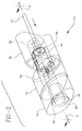
- an adapter 10 of the present invention for attaching a fluid handling device to a catheter 12 includes a body 14 with a proximal end 16, a distal end 18 and a passageway 20 therethrough defining a longitudinal axis A and an outside surface 21.
- Proximal end 16 includes a fitting 22, preferably a female luer fitting 24, to attach a fluid handling device.
- Distal end 18 of body 14 includes a receptacle 26 with an interior surface 27 to accept, and to form a releasable substantially fluid tight connection to preselected catheter tube 12 with an outside diameter "a".
- Adapter 10 has a latch member 30 disposed over receptacle 26.
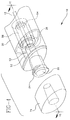
- Latch member 30 has an axial access port 32 therein with an inside surface 34 to receive a proximal end 36 of catheter tube 12 for placement into receptacle 26, latch member 30 is disposed for rotatable movement with to respect to body 14 between an insertion position, best seen in Figs 1, 2 and 6, where receptacle 26 is accessible to catheter 12 and a latched position, best seen in Figs. 4 and 7 to retain catheter 12 in receptacle 26. As shown in Fig.
- latch 30 and body 14 are preferably each formed in shape of an elongate tube with substantially identical elliptical cross-sections, each shape having a long axis "x, x' ", respectively, and a short axis “y,y' “, respectively, and disposed so that when latch 30 is in the latched position with respect to body 14, as seen in Fig. 4, long axes x,x' and short axes y,y' are substantially aligned and when latch 30 is in the insertion position as seen in Fig.
- short axis y of body 14 is substantially aligned with long axis x' of latch 30 with long axis x of the body being substantially aligned with short axis y' of latch 30, thereby providing a visual and tactile indication of the position of latch 30 with respect to body 14 and leverage to facilitate the practitioner's rotatable movement of latch 30 with respect to body 14.
- Many other shapes having asymmetric cross-sections, in addition to the preferred elliptical shape, for adapter 10 may be envisioned and are considered to be within the scope of the invention.
- an additional benefit of the preferred elongate elliptical shape for the adapter of the invention is that the preferred shape is less likely than the currently available adapters to cause discomfort to the patient by being pressed into the patient's flesh while providing an enlarged surface area for the practitioner to apply tape for securing the adapter to the patient.
- Adapter 10 of the invention is substantially easier for a gloved practitioner to handle than most currently available adapters because of the preferred elongate eliptical shape.
- Receptacle 26 is generally coaxial with passageway 20 with an open distal end 38 and has a closed bottom 40 defining a catheter seat 42 for fluidly connecting a lumen 44 of catheter 12 to proximal fitting 24.
- Receptacle 26 has a depth "d” and an inside diameter "e”.
- Catheter seat 42 includes an axial recess 48 therein that has an axial opening 50 in closed bottom 40 of receptacle 26.
- Recess 48 is sized to receive proximal end 36 of the catheter.
- Receptacle 26 includes a generally cylindrical resilient member 56 that is disposed substantially coaxially within the receptacle.
- Resilient member 56 has a proximal end 58, a distal end 60 and has an axial bore 61 therethrough.
- Resilient member 56 has an outside diameter "f” sized to fit within receptacle 26 and a length "g” substantially equal to depth "d” of receptacle 26.
- Axial bore 61 of resilient member 56 has an inside diameter "h” that is larger than outside diameter "a” of preselected catheter 12. While the outside surface of the body and the latch of the adapter may have a textured surface to facilitate handling by a gloved practitioner, preferably, as seen in Figs.
- body 14 has a substantially transparent viewing area 52 so that when the proximal end 36 of the catheter is properly positioned in recess 48 of catheter seat 42 with lumen 44 of the catheter substantially aligned with opening 50, proximal end 36 of the catheter is visible to the practitioner through area 52.
- transparent viewing area 52 is preferably formed into a shape 53, such as a cylinder lens or any other shape to provide an enlarged image of recess 48, thereby enhancing the practitioner's visualization of proper placement of the catheter.
- outside surface 21 of body 14 includes at least one, preferably two recessed, camming surfaces 62 and latch member 30 includes at least one, preferably two projecting, cam followers 64 disposed to engage camming surfaces 62.
- latch member 30 also has a compression member 66 disposed to engage resilient member 56.
- receptacle 26 further includes a washer 54 disposed proximally to compression member 66 with resilient member 56 proximal to washer 54.
- latch member 30 is advanced proximally from a distance "m” distal to body 14 to a distance "n” distal to body 14.
- latch member 30 is substantially in contact with body 14, i.e., distance "n” is substantially zero.
- compression member 66 applying a compressive force against washer 54 to compress resilient member 56 against closed bottom 40 and inside surface 27 of receptacle 26 and thereby reduce inside diameter "h" of axial bore 61.
- washer 54 provides a surface 55 for distal end 60 of the resilient member to be compressed against and allows for rotation of latch member 30 with respect to the resilient member during compression to substantially reduce any tendency of the resilient member twist and to occlude the catheter lumen.
- a profile 68 of camming surfaces 62 is selected so that the rotatable movement of latch 30 with respect to body 14 is less than about one half turn and, preferably, only about one quarter turn.
- Camming surfaces 62 further preferably include at least one protuberance 70 that is sized and positioned to releasably retain cam followers 64 when latch 30 is moved to the latched position, thus retaining adapter 10 on catheter 12 until the practitioner desires its release.
- protuberances 70 are sized and shaped so as to produce a "snap" when latch 30 is moved between the unlatched and the latched position to provide the practitioner with a positive aural and tactile indication that the movement from one position to another is complete.
- axial access port 32 provides that a force for inserting preselected catheter tube 12 into adapter 10 is less than a force for withdrawal of catheter tube 12 from the adapter before latch 30 is moved with respect to body 14, thereby substantially reducing inadvertent catheter tube withdrawal from the adapter prior to latching.
- this differential withdrawal force of the catheter is provided by having at least one inward projection 72 on inside surface 34 of axial access port 32.
- Projection 72 is preferably disposed to facilitate proximal motion of catheter tube 12 and to provide a resistance to distal motion of catheter tube 12.
- inside surface 34 of access port 32 preferably has two inward projections.
- resilient member 56 is preferably provided with flexible flaps 73 that partially obstruct the axial bore 61 at proximal end 58.
- Flexible flaps 73 result from the gate used to fill a cavity for forming resilient member 56 when an injection molding process is selected for the formation.
- Flexible flaps 73 deflect as the catheter is inserted and contribute to the retention of catheter 12 in the adapter prior to latching.
- flexible flaps 73 are illustrated proximally in the adapter. The retention function of flaps 73 is also seen when the orientation of resilient member results in the flaps being positioned distally, thus substantially eliminating the need to proximally or distally orient the placement of the resilient member during assembly of adapter 10.
- epidural catheters are sized between about 19 gauge to about 21 gauge (outside diameter between about 1.1 mm to about 0.8 mm) and the adapter of the invention is preferably sized to accept these sizes.
- Other sizes of catheter tubing may be required for other applications from between about 16 gauge to about 30 gauge (outside diameter between about 1.65 mm to about 0.3 mm) and adapter 10 may be sized to accept these sizes or to accept other sizes for any other particular application.
- adapter 10 is preferably supplied with a cap 74 over luer fitting 24.
- cap 74 is formed with substantially the same cross-sectional shape that is selected for the adapter to facilitate handling by the practitioner.
- Body 14, cap 74 and latch member 30 may be formed from thermoplastics such as polypropylene, polycarbonate, polyamide, polyester, polyethylene, acrylonitrile/butadiene/styrene (ABS) and the like, but preferably, at least body 14 is formed from a substantially transparent material such as polycarbonate and the like to ensure that the proximal end of the catheter is readily visible through viewing area 52.
- Resilient member 56 may be formed from either thermoform or thermoset elastomeric materials including, but not limited to natural rubber, ethylene propylene dimer rubber (EPDM), styrene butadiene rubber (SBR), silastic rubber and the like that have a Shore A durometer preferably between about 30 and 80.
- Preferably resilient member 56 is formed from a latex free natural rubber.
- Washer 54 may be formed from a metallic material, stainless steel or the like, or other material with a low coefficient of sliding friction with either the body or the resilient member. Polycarbonate is preferred as a material for forming washer 54. All of the materials selected to form adapter 10 should be resistant to and compatible with body fluids and medications. Additionally, when material selection is made for body 14 and latch member 30, the coefficient of sliding friction between the body and latch materials should be considered so that latch 30 is readily rotatable between the latched and the unlatched position. Additionally, since preferably, the adapter of the invention is generally supplied pre-sterilized to the practitioner, either as a separate item in a package or as a component in a procedure kit, the materials selected for adapter 10 should be compatible with the particular sterilization conditions selected.
- the adapter of the invention provides a practitioner with an easy-to-use adapter that is readily fitted onto a catheter tube. Proper placement of the tube on the catheter seat is readily apparent to the practitioner through the viewing area and, because of the projections in the access port and the flaps in the resilient member, the catheter tube is less likely to fall out of the adapter of the invention before if is latched. Further, the invention provides the practitioner with positive indications that the adapter is ready to receive the catheter, when the catheter is properly positioned in the adapter and when the adapter is fully engaged to retain the catheter.
- the preferred elongate elliptical shape of the adapter of the invention is more easily handled by a gloved practitioner than the mostly cylindrical adapters currently available.
Applications Claiming Priority (2)
| Application Number | Priority Date | Filing Date | Title |
|---|---|---|---|
| US79264097A | 1997-01-31 | 1997-01-31 | |
| US792640 | 1997-01-31 |
Publications (1)
| Publication Number | Publication Date |
|---|---|
| EP0856332A1 true EP0856332A1 (en) | 1998-08-05 |
Family
ID=25157572
Family Applications (1)
| Application Number | Title | Priority Date | Filing Date |
|---|---|---|---|
| EP98300705A Withdrawn EP0856332A1 (en) | 1997-01-31 | 1998-01-30 | Adapter for mounting a fluid handling device on a catheter tubing |
Country Status (4)
| Country | Link |
|---|---|
| EP (1) | EP0856332A1 (ja) |
| JP (1) | JP2904275B2 (ja) |
| AU (1) | AU5284998A (ja) |
| CA (1) | CA2227942A1 (ja) |
Cited By (12)
| Publication number | Priority date | Publication date | Assignee | Title |
|---|---|---|---|---|
| WO1999013938A1 (en) * | 1997-09-17 | 1999-03-25 | Becton, Dickinson And Company | Adapter for mounting a fluid handling device on a catheter tubing |
| EP1181946A1 (en) * | 2000-08-04 | 2002-02-27 | Alan David Mogg | Catheter adapter |
| WO2006099306A2 (en) | 2005-03-10 | 2006-09-21 | Custom Medical Applications, Inc. | Catheter connection hub |
| WO2011018092A1 (en) * | 2009-08-14 | 2011-02-17 | Coloplast A/S | An anal probe and a complementary connector |
| WO2012049532A1 (en) * | 2010-12-16 | 2012-04-19 | Becton Dickinson France | Adaptor and drug delivery device |
| US8366648B2 (en) | 2007-11-16 | 2013-02-05 | Gambro Lundia Ab | Medical connector able to connect specific medical tube and input port |
| US9333323B2 (en) | 2011-10-28 | 2016-05-10 | Custom Medical Applications, Inc. | Stylet assemblies, catheter kits and assemblies including stylet asssemblies, and related methods |
| USD781416S1 (en) | 2014-04-25 | 2017-03-14 | Custom Medical Applications, Inc. | Medical device handle |
| EP3145571A1 (en) * | 2014-05-20 | 2017-03-29 | Avent, Inc. | Catheter connector insert |
| CN111450407A (zh) * | 2015-06-12 | 2020-07-28 | 贝克顿迪金森有限公司 | 注射器适配器 |
| US11013865B2 (en) | 2013-10-15 | 2021-05-25 | Becton Dickinson France | Tip cap assembly for closing an injection system |
| WO2021224585A1 (en) * | 2020-05-04 | 2021-11-11 | Smiths Medical International Limited | Closed-system suction catheter assemblies and methods |
Families Citing this family (2)
| Publication number | Priority date | Publication date | Assignee | Title |
|---|---|---|---|---|
| JP4894524B2 (ja) * | 2007-01-15 | 2012-03-14 | ニプロ株式会社 | 簡易注出具 |
| KR20110033892A (ko) * | 2009-12-23 | 2011-04-01 | 신현순 | 카데터 및 카데터 조립체 |
Citations (4)
| Publication number | Priority date | Publication date | Assignee | Title |
|---|---|---|---|---|
| US5053015A (en) | 1989-08-30 | 1991-10-01 | The Kendall Company | Locking catheter adapter |
| US5224939A (en) * | 1992-05-22 | 1993-07-06 | Scimed Life Systems, Inc. | Self locking guide catheter |
| US5226898A (en) | 1989-08-30 | 1993-07-13 | The Kendall Company | Catheter adapter with strain relief |
| EP0658358A1 (en) * | 1993-11-19 | 1995-06-21 | Novoste Corporation | Fluid access and flow control valve |
-
1998
- 1998-01-26 CA CA 2227942 patent/CA2227942A1/en not_active Abandoned
- 1998-01-28 JP JP10014703A patent/JP2904275B2/ja not_active Expired - Lifetime
- 1998-01-30 AU AU52849/98A patent/AU5284998A/en not_active Abandoned
- 1998-01-30 EP EP98300705A patent/EP0856332A1/en not_active Withdrawn
Patent Citations (4)
| Publication number | Priority date | Publication date | Assignee | Title |
|---|---|---|---|---|
| US5053015A (en) | 1989-08-30 | 1991-10-01 | The Kendall Company | Locking catheter adapter |
| US5226898A (en) | 1989-08-30 | 1993-07-13 | The Kendall Company | Catheter adapter with strain relief |
| US5224939A (en) * | 1992-05-22 | 1993-07-06 | Scimed Life Systems, Inc. | Self locking guide catheter |
| EP0658358A1 (en) * | 1993-11-19 | 1995-06-21 | Novoste Corporation | Fluid access and flow control valve |
Cited By (23)
| Publication number | Priority date | Publication date | Assignee | Title |
|---|---|---|---|---|
| WO1999013938A1 (en) * | 1997-09-17 | 1999-03-25 | Becton, Dickinson And Company | Adapter for mounting a fluid handling device on a catheter tubing |
| US5992899A (en) * | 1997-09-17 | 1999-11-30 | Becton, Dickinson And Company | Adapter for mounting a fluid handling device on a catheter tubing |
| EP1181946A1 (en) * | 2000-08-04 | 2002-02-27 | Alan David Mogg | Catheter adapter |
| US6676652B2 (en) | 2000-08-04 | 2004-01-13 | Alan David Mogg | Catheter adapter |
| WO2006099306A2 (en) | 2005-03-10 | 2006-09-21 | Custom Medical Applications, Inc. | Catheter connection hub |
| EP1855738A2 (en) * | 2005-03-10 | 2007-11-21 | Custom Medical Applications, Inc. | Catheter connection hub |
| EP1855738A4 (en) * | 2005-03-10 | 2010-07-21 | Custom Med Applications Inc | CATHETER CONNECTOR |
| US8500715B2 (en) | 2005-03-10 | 2013-08-06 | Custom Medical Applications, Inc. | Catheter connection hub |
| US8038667B2 (en) | 2005-03-10 | 2011-10-18 | Custom Medical Applications, Inc. | Catheter connection hub |
| US8366648B2 (en) | 2007-11-16 | 2013-02-05 | Gambro Lundia Ab | Medical connector able to connect specific medical tube and input port |
| WO2011018092A1 (en) * | 2009-08-14 | 2011-02-17 | Coloplast A/S | An anal probe and a complementary connector |
| WO2012049532A1 (en) * | 2010-12-16 | 2012-04-19 | Becton Dickinson France | Adaptor and drug delivery device |
| US11383039B2 (en) | 2010-12-16 | 2022-07-12 | Becton Dickinson France | Adaptor and drug delivery device |
| US9717855B2 (en) | 2010-12-16 | 2017-08-01 | Becton Dickinson France | Adaptor and drug delivery device |
| US10391248B2 (en) | 2010-12-16 | 2019-08-27 | Becton Dickinson France | Adaptor and drug delivery device |
| US9333323B2 (en) | 2011-10-28 | 2016-05-10 | Custom Medical Applications, Inc. | Stylet assemblies, catheter kits and assemblies including stylet asssemblies, and related methods |
| US11013865B2 (en) | 2013-10-15 | 2021-05-25 | Becton Dickinson France | Tip cap assembly for closing an injection system |
| USD781416S1 (en) | 2014-04-25 | 2017-03-14 | Custom Medical Applications, Inc. | Medical device handle |
| EP3145571B1 (en) * | 2014-05-20 | 2021-06-23 | Avent, Inc. | Catheter connector insert |
| EP3145571A1 (en) * | 2014-05-20 | 2017-03-29 | Avent, Inc. | Catheter connector insert |
| CN111450407A (zh) * | 2015-06-12 | 2020-07-28 | 贝克顿迪金森有限公司 | 注射器适配器 |
| CN111450407B (zh) * | 2015-06-12 | 2023-02-10 | 贝克顿迪金森有限公司 | 注射器适配器 |
| WO2021224585A1 (en) * | 2020-05-04 | 2021-11-11 | Smiths Medical International Limited | Closed-system suction catheter assemblies and methods |
Also Published As
| Publication number | Publication date |
|---|---|
| JPH10211288A (ja) | 1998-08-11 |
| JP2904275B2 (ja) | 1999-06-14 |
| MX9800785A (es) | 1998-10-31 |
| CA2227942A1 (en) | 1998-07-31 |
| AU5284998A (en) | 1998-08-06 |
Similar Documents
| Publication | Publication Date | Title |
|---|---|---|
| US5992899A (en) | Adapter for mounting a fluid handling device on a catheter tubing | |
| EP0941743B1 (en) | Adapter for mounting a fluid handling device on a catheter tubing | |
| CN103140258B (zh) | 非鲁尔连接器 | |
| US10046155B2 (en) | Luer connector | |
| US9539419B2 (en) | Male connector and transfusion line connection apparatus equipped with male connector | |
| EP0856332A1 (en) | Adapter for mounting a fluid handling device on a catheter tubing | |
| US5292308A (en) | Three piece intravenous line connector | |
| EP0419620B1 (en) | Pre-slit injection site and tapered cannula | |
| US6676652B2 (en) | Catheter adapter | |
| CA2926024C (en) | Catheter connector | |
| GB2537356A (en) | Fluid transfer devices | |
| JP2002000722A (ja) | チューブ、継管具、接続口作製具および継管システム | |
| WO1995005863A1 (en) | Needleless iv medical delivery system | |
| MXPA98000785A (en) | Adapter to install, in a catheter pipe, a device for the handling of flui | |
| CA2170237A1 (en) | Needleless iv medical delivery system | |
| EP0715528A1 (en) | Needleless iv medical delivery system |
Legal Events
| Date | Code | Title | Description |
|---|---|---|---|
| PUAI | Public reference made under article 153(3) epc to a published international application that has entered the european phase |
Free format text: ORIGINAL CODE: 0009012 |
|
| AK | Designated contracting states |
Kind code of ref document: A1 Designated state(s): DE ES FR GB IT |
|
| AX | Request for extension of the european patent |
Free format text: AL;LT;LV;MK;RO;SI |
|
| 17P | Request for examination filed |
Effective date: 19990203 |
|
| AKX | Designation fees paid |
Free format text: DE ES FR GB IT |
|
| RBV | Designated contracting states (corrected) |
Designated state(s): DE ES FR GB IT |
|
| STAA | Information on the status of an ep patent application or granted ep patent |
Free format text: STATUS: THE APPLICATION IS DEEMED TO BE WITHDRAWN |
|
| 18D | Application deemed to be withdrawn |
Effective date: 20000801 |