EP0855729A1 - Hochempfindliches Relais und Verfahren zum Beschichten von Kontaktoberläche eines hochempfindliches Relais - Google Patents
Hochempfindliches Relais und Verfahren zum Beschichten von Kontaktoberläche eines hochempfindliches Relais Download PDFInfo
- Publication number
- EP0855729A1 EP0855729A1 EP98400006A EP98400006A EP0855729A1 EP 0855729 A1 EP0855729 A1 EP 0855729A1 EP 98400006 A EP98400006 A EP 98400006A EP 98400006 A EP98400006 A EP 98400006A EP 0855729 A1 EP0855729 A1 EP 0855729A1
- Authority
- EP
- European Patent Office
- Prior art keywords
- pallet
- cylinder head
- relay
- magnetic
- polar
- Prior art date
- Legal status (The legal status is an assumption and is not a legal conclusion. Google has not performed a legal analysis and makes no representation as to the accuracy of the status listed.)
- Granted
Links
- 238000000576 coating method Methods 0.000 title claims description 38
- 239000011248 coating agent Substances 0.000 title claims description 29
- 238000000034 method Methods 0.000 title claims description 8
- OKTJSMMVPCPJKN-UHFFFAOYSA-N Carbon Chemical compound [C] OKTJSMMVPCPJKN-UHFFFAOYSA-N 0.000 claims abstract description 18
- 229910052799 carbon Inorganic materials 0.000 claims abstract description 18
- 229910003460 diamond Inorganic materials 0.000 claims abstract description 16
- 239000010432 diamond Substances 0.000 claims abstract description 16
- 238000006073 displacement reaction Methods 0.000 claims abstract description 3
- 238000005229 chemical vapour deposition Methods 0.000 claims abstract 2
- 230000005291 magnetic effect Effects 0.000 claims description 31
- 230000035945 sensitivity Effects 0.000 claims description 19
- 238000004804 winding Methods 0.000 claims description 7
- 239000000696 magnetic material Substances 0.000 claims description 5
- 239000004215 Carbon black (E152) Substances 0.000 claims description 2
- 238000001514 detection method Methods 0.000 claims description 2
- 229930195733 hydrocarbon Natural products 0.000 claims description 2
- 150000002430 hydrocarbons Chemical class 0.000 claims description 2
- 239000000463 material Substances 0.000 claims description 2
- 238000004026 adhesive bonding Methods 0.000 claims 1
- 230000001131 transforming effect Effects 0.000 claims 1
- 238000000151 deposition Methods 0.000 abstract description 2
- 230000008021 deposition Effects 0.000 abstract description 2
- 238000000407 epitaxy Methods 0.000 abstract 1
- 239000010410 layer Substances 0.000 description 11
- 239000011247 coating layer Substances 0.000 description 10
- 230000007797 corrosion Effects 0.000 description 9
- 238000005260 corrosion Methods 0.000 description 9
- PXHVJJICTQNCMI-UHFFFAOYSA-N Nickel Chemical compound [Ni] PXHVJJICTQNCMI-UHFFFAOYSA-N 0.000 description 8
- 229910000990 Ni alloy Inorganic materials 0.000 description 5
- VYZAMTAEIAYCRO-UHFFFAOYSA-N Chromium Chemical compound [Cr] VYZAMTAEIAYCRO-UHFFFAOYSA-N 0.000 description 4
- 229910045601 alloy Inorganic materials 0.000 description 4
- 239000000956 alloy Substances 0.000 description 4
- 150000001875 compounds Chemical class 0.000 description 4
- 229910052751 metal Inorganic materials 0.000 description 4
- 239000002184 metal Substances 0.000 description 4
- 229910052759 nickel Inorganic materials 0.000 description 4
- KDLHZDBZIXYQEI-UHFFFAOYSA-N Palladium Chemical compound [Pd] KDLHZDBZIXYQEI-UHFFFAOYSA-N 0.000 description 3
- 229910001252 Pd alloy Inorganic materials 0.000 description 3
- RTAQQCXQSZGOHL-UHFFFAOYSA-N Titanium Chemical compound [Ti] RTAQQCXQSZGOHL-UHFFFAOYSA-N 0.000 description 3
- 229910052804 chromium Inorganic materials 0.000 description 3
- 239000011651 chromium Substances 0.000 description 3
- 239000007789 gas Substances 0.000 description 3
- 229910001004 magnetic alloy Inorganic materials 0.000 description 3
- 230000007257 malfunction Effects 0.000 description 3
- 230000003647 oxidation Effects 0.000 description 3
- 238000007254 oxidation reaction Methods 0.000 description 3
- 229910052719 titanium Inorganic materials 0.000 description 3
- 239000010936 titanium Substances 0.000 description 3
- NRTOMJZYCJJWKI-UHFFFAOYSA-N Titanium nitride Chemical compound [Ti]#N NRTOMJZYCJJWKI-UHFFFAOYSA-N 0.000 description 2
- UORVGPXVDQYIDP-UHFFFAOYSA-N borane Chemical compound B UORVGPXVDQYIDP-UHFFFAOYSA-N 0.000 description 2
- 150000001722 carbon compounds Chemical class 0.000 description 2
- 238000005234 chemical deposition Methods 0.000 description 2
- 230000007423 decrease Effects 0.000 description 2
- 230000004907 flux Effects 0.000 description 2
- 230000007935 neutral effect Effects 0.000 description 2
- BSIDXUHWUKTRQL-UHFFFAOYSA-N nickel palladium Chemical compound [Ni].[Pd] BSIDXUHWUKTRQL-UHFFFAOYSA-N 0.000 description 2
- 239000012808 vapor phase Substances 0.000 description 2
- 229910001020 Au alloy Inorganic materials 0.000 description 1
- ATJFFYVFTNAWJD-UHFFFAOYSA-N Tin Chemical compound [Sn] ATJFFYVFTNAWJD-UHFFFAOYSA-N 0.000 description 1
- 125000004429 atom Chemical group 0.000 description 1
- 229910000085 borane Inorganic materials 0.000 description 1
- 125000004432 carbon atom Chemical group C* 0.000 description 1
- 230000015556 catabolic process Effects 0.000 description 1
- 238000006243 chemical reaction Methods 0.000 description 1
- 230000008878 coupling Effects 0.000 description 1
- 238000010168 coupling process Methods 0.000 description 1
- 238000005859 coupling reaction Methods 0.000 description 1
- 238000006731 degradation reaction Methods 0.000 description 1
- 230000006866 deterioration Effects 0.000 description 1
- 239000002019 doping agent Substances 0.000 description 1
- 238000005868 electrolysis reaction Methods 0.000 description 1
- 239000003302 ferromagnetic material Substances 0.000 description 1
- PCHJSUWPFVWCPO-UHFFFAOYSA-N gold Chemical compound [Au] PCHJSUWPFVWCPO-UHFFFAOYSA-N 0.000 description 1
- 229910052737 gold Inorganic materials 0.000 description 1
- 239000010931 gold Substances 0.000 description 1
- 229910052739 hydrogen Inorganic materials 0.000 description 1
- 239000001257 hydrogen Substances 0.000 description 1
- 125000004435 hydrogen atom Chemical class [H]* 0.000 description 1
- 150000002739 metals Chemical class 0.000 description 1
- 150000004767 nitrides Chemical class 0.000 description 1
- 239000012071 phase Substances 0.000 description 1
- 239000011253 protective coating Substances 0.000 description 1
- 230000002829 reductive effect Effects 0.000 description 1
- 230000000284 resting effect Effects 0.000 description 1
- 239000000126 substance Substances 0.000 description 1
Images
Classifications
-
- H—ELECTRICITY
- H01—ELECTRIC ELEMENTS
- H01H—ELECTRIC SWITCHES; RELAYS; SELECTORS; EMERGENCY PROTECTIVE DEVICES
- H01H71/00—Details of the protective switches or relays covered by groups H01H73/00 - H01H83/00
- H01H71/10—Operating or release mechanisms
- H01H71/12—Automatic release mechanisms with or without manual release
- H01H71/24—Electromagnetic mechanisms
- H01H71/32—Electromagnetic mechanisms having permanently magnetised part
- H01H71/327—Manufacturing or calibrating methods, e.g. air gap treatments
Definitions
- the invention relates to a high sensitivity relay. and a method of coating contact surfaces a high sensitivity relay.
- the invention applies to a high sensitivity relay constituting a mechanical actuator for a circuit breaker or a Differential Switch.
- Such high sensitivity relays are realized in the form of a magnetic circuit comprising a cylinder head and a pallet made of ferromagnetic material weak coercive field.
- the magnetic circuit which presents for example a rectangular shape has a cylinder head having the shape of a C with two branches parallel have end portions constituting polar surfaces to which apply two contact areas of the pallet made under the shape of a flat blade, in the closed position of the relay.
- the cylinder head and the pallet are made up of magnetic parts made of a nickel alloy such as 50% alloy or 80% nickel alloy. These parts are processed at high temperature (at a temperature above 1000 ° C in a neutral or reducing atmosphere) so that the magnetic pieces have very weak coercive fields and for example coercive fields less than or equal to 150mA / cm).
- a permanent magnet associated with the cylinder head and coupled to the magnetic circuit allows to exert a force of attraction on the pallet, so that it is held against the end parts of the cylinder head comprising the polar surfaces.
- a spring for example helical fixed at one of its ends on the pallet in the vicinity of a first contact area of the pallet with a first polar surface of the cylinder head and at its other end on a part secured to the cylinder head allows to exert on the pallet a restoring force in a direction tending to move the second contact zone away from the pallet of the second polar surface of the cylinder head by pivoting the pallet around an axis of rotation located at the first polar surface.
- a coil is placed around part of the breech close to its second polar surface.
- the winding is supplied with electric current via a magnetic torus ensuring the detection of faults in the electrical circuit on which the circuit breaker.
- the magnetic flux generated by the magnet decreases, which results in a decrease in the bonding effort exerted by the magnet on the pallet, so that the force exerted by the spring becomes predominant; the spring is then able to move the pallet, by pivot, to an open position. Move of the pallet from its closed circuit position magnetic to an open position allows actuation the mechanical circuit breaker control device.
- the movement of the pallet by pivoting between its position closing and its open position is accompanied a certain slip between the first bearing surface of the pallet and the first polar surface of the breech when rotating around the edge of the first polar surface.
- the resulting friction may cause some wear of the magnetic parts.
- the second contact area of the pallet which comes to rest against the second polar surface of the cylinder head undergoes some wear during operation successive stages of the relay.
- the magnetic parts of the relay i.e. the cylinder head and pallet must have a coercive field very weak and always less than 150mA / cm.
- the relays must be able to carry out a very large number of operations without their performance are significantly degraded.
- the air gap between the magnetic pieces in their position closing must be kept low and constant.
- the polar surfaces of the cylinder head and the contact surfaces of the pallet must have a very good surface condition, so they must undergo a minimal degradation and wear during operation of the relay.
- the surfaces of the magnetic parts must withstand the climatic tests described in the French standard NFC.EN.61009.
- magnetic alloys based on nickel used especially when processed thermally to present a weak coercive field, have low hardness and low wear resistance.
- these nickel alloys are not stainless and their resistance to corrosion under conditions of use of the relay is insufficient. So we proposed improve the hardness and wear resistance of contact surfaces of the magnetic parts of the relays producing metallic coatings on these surfaces which also increase corrosion resistance contact surfaces.
- These protective coatings can be produced by a process such as electrolysis, chemical deposition vapor phase (CVD) or chemical phase deposition plasma activated steam (PECVD).
- CVD chemical deposition vapor phase
- PECVD chemical phase deposition plasma activated steam
- the choice of metal deposited to constitute the coating layer must allow certain conditions with regard to the characteristics of the coating layer.
- the layer must be thick limited so that we can get an air gap between the contact areas of the pallet and the polar surfaces of the cylinder head of a perfectly defined thickness and less than a low value of the order of 5 ⁇ m.
- the hardness of the coating layer must be high to limit wear on the contact between the pallet and the cylinder head, during a use resulting in a very large number of relay operations.
- the coefficient of friction of the surfaces of contact with each other must be weak, especially because the hinge axis of the pallet can be at one of the polar surfaces of the cylinder head.
- the hardness of the deposited layers is not generally not sufficient to provide long duration of the relay.
- the object of the invention is to propose a relay high sensitivity with magnetic circuit
- a relay high sensitivity with magnetic circuit comprising a cylinder head of magnetic material having a first and second polar surfaces and a palette consisting of a blade, made of a magnetic material, having on one of its faces or bearing face, a first and a second respective contact zone with the first and the second polar surface of the breech, in a closed position of the magnetic circuit, means of attraction of the pallet towards the closed position and means for recalling and moving the pallet by pivoting about an axis which can be located on the first polar surface of the cylinder head, towards a position opening in which the second contact area of the pallet is separated from the second polar surface of the cylinder head, this relay can have a very large air gap weak and perfectly defined between the surfaces of contact of the pallet and the cylinder head, a very large resistance to wear and oxidation and a coefficient very low friction between the contact surfaces.
- At least one of the bearing surfaces constituted by the support surface of the pallet of a part and the polar surfaces of the cylinder head on the other hand, is covered by a coating containing carbon in the form of a diamond.
- the invention also relates to a method for coating the contact surfaces of a high relay sensitivity.
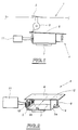
- Figure 1 is a schematic view of a circuit breaker comprising a high sensitivity relay according to the invention.
- Figure 2 is a perspective view of a high sensitivity relay according to the invention.
- a contactor 2 On a line of network 1 is placed a contactor 2 which can be moved by a mechanical device 3 actuated by a high sensitivity relay 4, to cut current flow in network 1, the whole comprising the contactor 2, the mechanical device 3, the relay 4 and a malfunction detector 11 of network 1 constituting the differential circuit breaker.
- the relay 4 consists of a magnetic circuit which comprises a yoke 5 made of magnetic material having the shape of a C and a pallet 6 consisting of a blade plane which ensures the closing of the magnetic circuit in a closed position shown in Figure 2.
- the cylinder head 5 has two branches substantially parallels 5a and 5b, the end parts of which constitute the polar surfaces of the cylinder head 5.
- the palette 6 has a bearing surface 6a (lower surface of the pallet in Figure 2) which comes into contact with the polar surfaces of the cylinder head 5, at the end of the branches 5a and 5b of the cylinder head, in the position of closing of the relay shown in figure 2.
- a permanent magnet 7 is fixed on the branch central cylinder head 5 joining the two branches parallel 5a and 5b and ensures by magnetic coupling with cylinder head 5, the attraction and bonding of the pallet 6 on the polar surfaces of the cylinder head, in the closed position of the relay.
- a return spring 8 formed in the form a coil spring is attached to one of its ends on an end part of the pallet, in the vicinity a first contact area of the pallet made up on its bearing surface coming into contact with the first polar surface of the breech at the end of branch 5a.
- Spring 8 is fixed at its second end on a fixing piece 9 fixed to the body of the relay or on the cylinder head.
- Spring 8 exerts a force on the pallet 6 in the opposite direction to the force of attraction of the second contact area of the pallet coming to rest on the second pole surface at the end of branch 5b of the cylinder head.
- a coil 10 surrounds the second branch 5b of the cylinder head 5.
- the winding 10 is supplied with current electric via fault detector 11 of operation of the electrical network 1 which can be constituted by a toroid detector capable of sending a current to the winding 10, in the case of the appearance a malfunction on the network 1.
- Pallet 6 of the relay in the open position activates the mechanism 3, so as to unlock it.
- Mechanism 3 exercises then a large force on the contactor blade 2 to ensure its displacement and the interruption of the current flow in the electrical network 1.
- Relay 4 must have a high sensitivity, the electrical triggering power of the relay in front be less than 250 ⁇ VA and preferably between 50 and 100 ⁇ VA. For this it is necessary to use to constitute the cylinder head 5 and the pallet 6 of the circuit relay 4, a high magnetic alloy performance whose coercive field is less than 150mA / cm. Generally a nickel alloy is used. 50 or 80% nickel. This alloy is further processed thermally at high temperature under neutral atmosphere or reductive.
- the alloys of used nickel have low wear resistance. In besides these alloys are not stainless.
- the spring 8 ensures the movement of the pallet 6 by pivoting around an axis 12 (see Figure 2) located on the first polar surface of the breech at the end of the branch 5a.
- the movement of the pallet 6 between its position however, its open position is not not purely a pivoting movement, some slip occurring between the first area of contact of the bearing surface 6a of the pallet and the first polar surface of the cylinder head 5. It occurs therefore a friction between the contact surfaces of the relay and, during successive uses of the relay, a wear of these contact areas.
- the maneuvers opening and closing of the relay cause a wear of the second contact area of the bearing surface 6a of the pallet against the second polar surface of the breech at the end of the branch 5b.
- the air gap high sensitivity relay i.e.
- the sum of air gaps between the first contact area of pallet 6 and the first polar surface of the cylinder head 5 on the one hand and the second contact zone of the pallet 6 and the second polar surface of the cylinder head 5 else hand, must have a very low value and perfectly constant to ensure satisfactory performance of relay over time.
- the relay air gap corresponding to the sum of air gaps at the contact zones of this relay must be as constant as possible and less than or equal at 5 ⁇ m.
- the polar surfaces of the cylinder head and the surface contact areas support 6a of the pallet have a very low roughness. These areas can for example be subject to rectification and running-in.
- the coefficient of friction of the palette on the cylinder head, especially at the first contact area of the pallet 6 resting on the first polar surface of the cylinder head must be very low.
- the resistance to wear and therefore the hardness of contact surfaces must also be very high.
- the high sensitivity relay according to the invention meets all of these conditions, because at least one of the bearing surfaces constituted by the bearing surface 6a of the pallet 6 on the one hand and by the polar surfaces at the end of branches 5a and 5b of the cylinder head on the other hand is covered with a layer of coating containing carbon in the form of a diamond.
- the relay according to the invention has a coating layer on only one of the bearing surfaces, the best results being obtained by making a coating layer containing carbon in the form of diamond on the bearing surface 6a of the pallet only.
- the polar surfaces of the cylinder head 5 are then simply rectified or lapped. Of course, it is also possible to donate both the polar surfaces of the cylinder head and the surfaces pallet support.
- the coating of the contact surface (s) of the relay is achieved by a chemical deposition process in vapor phase assisted by a plasma (PECVD process).
- the part to be coated for example the heat treated magnetic alloy constituting the pallet 6 is introduced into a chamber in which we can create a vacuum.
- the room is evacuated and we introduces into the chamber a gas containing carbon, for example a hydrocarbon.
- a doping agent such as a borane.
- Such a compound is known by the name D.L.C. or under the trade name Diamolith Carbon.
- the duration of the coating treatment is set so as to obtain a coating with a thickness desirable.
- a coating layer containing a high proportion of carbon in the form of diamond having a thickness close to 1 ⁇ m. So more general, we will aim for a coating thickness between 0.5 and 2 ⁇ m.
- the last column of the table relates to a coating of a contact surface of a next relay the invention.
- Corrosion resistance tests have been carried out according to French standard NFC.EN.61009.
- the relay is placed in the closed position and exposed, during 24 hour exposure cycles to an atmosphere containing 100% humidity, at a temperature of 70 ° C, for twenty-eight days.
- the coating layer according to the invention has a hardness significantly higher than the hardness other coatings including coatings titanium nitride and carbonitride.
- the contact surfaces of the following relays the invention therefore exhibit resistance to wear significantly higher than the wear resistance relays with metallic coatings of the type known.
- This resistance to wear and the operation of the relays are also improved by the fact that the coefficient friction between the coated contact surfaces of a diamond-like carbon compound is much lower than the coefficient of friction of coatings metallic.
- Coating of relay contact surfaces according to the invention also has a critical charge chipping and tear resistance satisfactory, these characteristics not being superior, for coatings according to the prior art, only in the hard chrome. Additionally, as noted above, the minimum coating thickness of the coating to be produced on the contact surfaces of a relay is substantially lower in the case of a relay according to the invention (0.5 ⁇ m) if compared to surface coatings of relay contact according to the prior art (thickness 1 or 2 ⁇ m).
- Relays according to the invention comprising on their contact surface a thin deposit perfectly smooth carbon compound in the form of diamond, therefore have very characteristic superior to known high-sensitivity relays the contact surfaces of which are coated with a layer metallic.
- a low deposit thickness and perfectly controlled provides a perfectly air gap constant and limited to a low value.
- the relay has a very strong resistance to oxidation, even in the case of using a deposit of thin.
- the high hardness of the coating makes on the other hand the relay according to the invention practically insensitive to wear, following a very large number of maneuvers.
- the low coefficient of friction between the contact surfaces helps limit deterioration of these contact surfaces, at the pivot axis of the pallet of the first polar zone of the breech.
- the coating which is carried out at a very moderate temperature does not deteriorate properties parts of the relay.
- the next relay the invention therefore has a triggering power which can be set to a low value and in particular less than 250 ⁇ VA.
- the invention is not limited to the embodiment that has been described.
- the invention applies to relays with high sensitivity different from relays constituting actuators for a circuit breaker or a differential switch of an electrical network.
Landscapes
- Engineering & Computer Science (AREA)
- Manufacturing & Machinery (AREA)
- Physics & Mathematics (AREA)
- Electromagnetism (AREA)
- Application Of Or Painting With Fluid Materials (AREA)
- Manufacture Of Switches (AREA)
- Electromagnets (AREA)
- Chemical Vapour Deposition (AREA)
- Magnetic Treatment Devices (AREA)
- Reciprocating, Oscillating Or Vibrating Motors (AREA)
- Contacts (AREA)
- Non-Silver Salt Photosensitive Materials And Non-Silver Salt Photography (AREA)
Applications Claiming Priority (2)
| Application Number | Priority Date | Filing Date | Title |
|---|---|---|---|
| FR9700798A FR2758904B1 (fr) | 1997-01-24 | 1997-01-24 | Relais a haute sensibilite et procede de revetement de surfaces de contact d'un relais a haute sensibilite |
| FR9700798 | 1997-01-24 |
Publications (2)
| Publication Number | Publication Date |
|---|---|
| EP0855729A1 true EP0855729A1 (de) | 1998-07-29 |
| EP0855729B1 EP0855729B1 (de) | 2001-03-28 |
Family
ID=9502966
Family Applications (1)
| Application Number | Title | Priority Date | Filing Date |
|---|---|---|---|
| EP98400006A Expired - Lifetime EP0855729B1 (de) | 1997-01-24 | 1998-01-05 | Hochempfindliches Relais und Verfahren zum Beschichten von Kontaktoberfläche eines hochempfindliches Relais |
Country Status (6)
| Country | Link |
|---|---|
| EP (1) | EP0855729B1 (de) |
| AT (1) | ATE200163T1 (de) |
| DE (1) | DE69800631T2 (de) |
| ES (1) | ES2157641T3 (de) |
| FR (1) | FR2758904B1 (de) |
| HU (1) | HU222292B1 (de) |
Cited By (2)
| Publication number | Priority date | Publication date | Assignee | Title |
|---|---|---|---|---|
| EP1109188A3 (de) * | 1999-12-14 | 2003-04-16 | GE Power Controls Iberica, S.L. | Verfahren zur Verlängerung der Lebensdauer eines elekromagnetischen Relais |
| CN110541150A (zh) * | 2019-08-22 | 2019-12-06 | 沈阳科友真空技术有限公司 | 一种干簧管继电器触点用多层膜结构及其制备方法 |
Families Citing this family (2)
| Publication number | Priority date | Publication date | Assignee | Title |
|---|---|---|---|---|
| US7863534B2 (en) | 2008-04-15 | 2011-01-04 | General Electric Company | Spring discharge mechanism for circuit breaker |
| DE102012009665B4 (de) * | 2012-05-12 | 2022-04-07 | Doepke Schaltgeräte GmbH | Elektrisches Auslöserelais für einen Schalter, insbesondere für einen Schutzschalter zum Überwachen elektrischer Netze |
Citations (3)
| Publication number | Priority date | Publication date | Assignee | Title |
|---|---|---|---|---|
| DE2836572A1 (de) * | 1978-08-21 | 1980-03-06 | Siemens Ag | Magnetisch betaetigbare kontakteinrichtung |
| JPH03276707A (ja) * | 1990-03-27 | 1991-12-06 | Matsushita Electric Works Ltd | 電磁石 |
| US5544774A (en) * | 1994-08-26 | 1996-08-13 | Aiwa Research And Development, Inc. | Method of eliminating pole recession in a thin film magnetic head |
-
1997
- 1997-01-24 FR FR9700798A patent/FR2758904B1/fr not_active Expired - Fee Related
-
1998
- 1998-01-05 DE DE69800631T patent/DE69800631T2/de not_active Expired - Lifetime
- 1998-01-05 AT AT98400006T patent/ATE200163T1/de not_active IP Right Cessation
- 1998-01-05 EP EP98400006A patent/EP0855729B1/de not_active Expired - Lifetime
- 1998-01-05 ES ES98400006T patent/ES2157641T3/es not_active Expired - Lifetime
- 1998-01-23 HU HU9800122A patent/HU222292B1/hu not_active IP Right Cessation
Patent Citations (3)
| Publication number | Priority date | Publication date | Assignee | Title |
|---|---|---|---|---|
| DE2836572A1 (de) * | 1978-08-21 | 1980-03-06 | Siemens Ag | Magnetisch betaetigbare kontakteinrichtung |
| JPH03276707A (ja) * | 1990-03-27 | 1991-12-06 | Matsushita Electric Works Ltd | 電磁石 |
| US5544774A (en) * | 1994-08-26 | 1996-08-13 | Aiwa Research And Development, Inc. | Method of eliminating pole recession in a thin film magnetic head |
Non-Patent Citations (1)
| Title |
|---|
| PATENT ABSTRACTS OF JAPAN vol. 16, no. 97 (E - 1176) 10 March 1992 (1992-03-10) * |
Cited By (3)
| Publication number | Priority date | Publication date | Assignee | Title |
|---|---|---|---|---|
| EP1109188A3 (de) * | 1999-12-14 | 2003-04-16 | GE Power Controls Iberica, S.L. | Verfahren zur Verlängerung der Lebensdauer eines elekromagnetischen Relais |
| CN110541150A (zh) * | 2019-08-22 | 2019-12-06 | 沈阳科友真空技术有限公司 | 一种干簧管继电器触点用多层膜结构及其制备方法 |
| CN110541150B (zh) * | 2019-08-22 | 2024-05-03 | 沈阳科友真空技术有限公司 | 一种干簧管继电器触点用多层膜结构及其制备方法 |
Also Published As
| Publication number | Publication date |
|---|---|
| FR2758904A1 (fr) | 1998-07-31 |
| HU222292B1 (hu) | 2003-06-28 |
| EP0855729B1 (de) | 2001-03-28 |
| FR2758904B1 (fr) | 1999-04-23 |
| DE69800631D1 (de) | 2001-05-03 |
| HU9800122D0 (en) | 1998-03-30 |
| ATE200163T1 (de) | 2001-04-15 |
| HUP9800122A3 (en) | 1999-11-29 |
| DE69800631T2 (de) | 2001-07-05 |
| ES2157641T3 (es) | 2001-08-16 |
| HUP9800122A2 (hu) | 1998-08-28 |
Similar Documents
| Publication | Publication Date | Title |
|---|---|---|
| CA2662734C (fr) | Procede pour deposer sur un substrat une couche mince d'alliage metallique et un alliage metallique sous forme de couche mince | |
| FR2664015A1 (fr) | Element d'obturation de robinet. | |
| FR2742917A1 (fr) | Dispositif miniature pour executer une fonction predeterminee, notamment microrelais | |
| EP0855729B1 (de) | Hochempfindliches Relais und Verfahren zum Beschichten von Kontaktoberfläche eines hochempfindliches Relais | |
| EP0119459B1 (de) | Stück, das ein mit einem harten und korrosionsfesten Überzug versehenes Substrat enthält | |
| CA2807067C (fr) | Dispositif de detection et de signalement du changement d'etat d'un bouton-poussoir | |
| KR20110040884A (ko) | 변색방지 은 합금 | |
| GB2130795A (en) | Electrical contacts | |
| EP0738787B1 (de) | Verfahren zur Herstellung eines diamantbeschichteten Metallkörpers | |
| FR2765724A1 (fr) | Alliage magnetique doux du type fe-ni-cr-ti pour circuit magnetique d'un relais a haute sensibilite | |
| EP0301935B1 (de) | Hochempfindlicher elektromagnetischer Auslöser und dessen Herstellung | |
| WO1990013685A1 (en) | Electric contact material, method of producing said material, and electric contact produced therefrom | |
| EP3309624B1 (de) | Montageverfahren für uhrenkomponenten | |
| WO2020148626A1 (fr) | Procédé de brasage de composants horlogers | |
| FR2823003A1 (fr) | Dispositif de declenchement en cas de phase ouverte et de surcharge pour un disjoncteur | |
| EP0838830B1 (de) | Elektromagnetischen Auslöser mit einer amorphen Kohlenstoffbeschichtung und sein Fertigungsverfahren | |
| EP0209433B1 (de) | Kontaktträger, insbesondere für Schutzschalter | |
| EP2311056B1 (de) | Fernsteuerungsvorrichtung für einen schalter mit einem verstärkungsmechanismus und einem drehgenerator und mit einer derartigen vorrichtung ausgestatteter schalter | |
| WO1984001662A1 (fr) | Percuteur a grande sensibilite | |
| EP4174584A1 (de) | Magnetischer mechanismus zur steuerung und/oder zum antrieb durch ein armbanduhrengehäuse | |
| EP3642496B1 (de) | Mechanisches modulteil | |
| FR2458732A1 (fr) | Mecanisme de securite electromagnetique | |
| EP1420083B1 (de) | Verfahren zur Abscheidung einer Oberflächenbeschichtung, die mindestens ein dünnen, homogenen Film aus Metall und kohlenstoff enthält, und dadurch hergestellte Oberflächenbeschichtung | |
| EP1647041B1 (de) | Mit einer testschaltung ausgestatteter differenz-schalter | |
| FR2793947A1 (fr) | Relais a haute sensibilite, et procede pour sa fabrication |
Legal Events
| Date | Code | Title | Description |
|---|---|---|---|
| PUAI | Public reference made under article 153(3) epc to a published international application that has entered the european phase |
Free format text: ORIGINAL CODE: 0009012 |
|
| 17P | Request for examination filed |
Effective date: 19980508 |
|
| AK | Designated contracting states |
Kind code of ref document: A1 Designated state(s): AT BE CH DE DK ES FI FR GB GR IE IT LI LU MC NL PT SE |
|
| AX | Request for extension of the european patent |
Free format text: AL;LT;LV;MK;RO;SI |
|
| AKX | Designation fees paid |
Free format text: AT BE CH DE DK ES FI FR GB GR IE IT LI LU MC NL PT SE |
|
| RBV | Designated contracting states (corrected) |
Designated state(s): AT BE CH DE DK ES FI FR GB GR IE IT LI LU MC NL PT SE |
|
| GRAG | Despatch of communication of intention to grant |
Free format text: ORIGINAL CODE: EPIDOS AGRA |
|
| 17Q | First examination report despatched |
Effective date: 20000613 |
|
| GRAG | Despatch of communication of intention to grant |
Free format text: ORIGINAL CODE: EPIDOS AGRA |
|
| GRAH | Despatch of communication of intention to grant a patent |
Free format text: ORIGINAL CODE: EPIDOS IGRA |
|
| GRAH | Despatch of communication of intention to grant a patent |
Free format text: ORIGINAL CODE: EPIDOS IGRA |
|
| GRAA | (expected) grant |
Free format text: ORIGINAL CODE: 0009210 |
|
| AK | Designated contracting states |
Kind code of ref document: B1 Designated state(s): AT BE CH DE DK ES FI FR GB GR IE IT LI LU MC NL PT SE |
|
| PG25 | Lapsed in a contracting state [announced via postgrant information from national office to epo] |
Ref country code: NL Free format text: LAPSE BECAUSE OF FAILURE TO SUBMIT A TRANSLATION OF THE DESCRIPTION OR TO PAY THE FEE WITHIN THE PRESCRIBED TIME-LIMIT Effective date: 20010328 Ref country code: IE Free format text: LAPSE BECAUSE OF FAILURE TO SUBMIT A TRANSLATION OF THE DESCRIPTION OR TO PAY THE FEE WITHIN THE PRESCRIBED TIME-LIMIT Effective date: 20010328 Ref country code: GB Free format text: LAPSE BECAUSE OF FAILURE TO SUBMIT A TRANSLATION OF THE DESCRIPTION OR TO PAY THE FEE WITHIN THE PRESCRIBED TIME-LIMIT Effective date: 20010328 Ref country code: FI Free format text: LAPSE BECAUSE OF FAILURE TO SUBMIT A TRANSLATION OF THE DESCRIPTION OR TO PAY THE FEE WITHIN THE PRESCRIBED TIME-LIMIT Effective date: 20010328 |
|
| REF | Corresponds to: |
Ref document number: 200163 Country of ref document: AT Date of ref document: 20010415 Kind code of ref document: T |
|
| ITF | It: translation for a ep patent filed | ||
| REG | Reference to a national code |
Ref country code: CH Ref legal event code: EP |
|
| REG | Reference to a national code |
Ref country code: IE Ref legal event code: FG4D Free format text: FRENCH |
|
| REF | Corresponds to: |
Ref document number: 69800631 Country of ref document: DE Date of ref document: 20010503 |
|
| PG25 | Lapsed in a contracting state [announced via postgrant information from national office to epo] |
Ref country code: SE Free format text: LAPSE BECAUSE OF FAILURE TO SUBMIT A TRANSLATION OF THE DESCRIPTION OR TO PAY THE FEE WITHIN THE PRESCRIBED TIME-LIMIT Effective date: 20010628 Ref country code: PT Free format text: LAPSE BECAUSE OF FAILURE TO SUBMIT A TRANSLATION OF THE DESCRIPTION OR TO PAY THE FEE WITHIN THE PRESCRIBED TIME-LIMIT Effective date: 20010628 Ref country code: DK Free format text: LAPSE BECAUSE OF FAILURE TO SUBMIT A TRANSLATION OF THE DESCRIPTION OR TO PAY THE FEE WITHIN THE PRESCRIBED TIME-LIMIT Effective date: 20010628 |
|
| PG25 | Lapsed in a contracting state [announced via postgrant information from national office to epo] |
Ref country code: GR Free format text: LAPSE BECAUSE OF FAILURE TO SUBMIT A TRANSLATION OF THE DESCRIPTION OR TO PAY THE FEE WITHIN THE PRESCRIBED TIME-LIMIT Effective date: 20010629 |
|
| REG | Reference to a national code |
Ref country code: ES Ref legal event code: FG2A Ref document number: 2157641 Country of ref document: ES Kind code of ref document: T3 |
|
| NLV1 | Nl: lapsed or annulled due to failure to fulfill the requirements of art. 29p and 29m of the patents act | ||
| GBV | Gb: ep patent (uk) treated as always having been void in accordance with gb section 77(7)/1977 [no translation filed] |
Effective date: 20010328 |
|
| REG | Reference to a national code |
Ref country code: IE Ref legal event code: FD4D |
|
| PLBE | No opposition filed within time limit |
Free format text: ORIGINAL CODE: 0009261 |
|
| STAA | Information on the status of an ep patent application or granted ep patent |
Free format text: STATUS: NO OPPOSITION FILED WITHIN TIME LIMIT |
|
| 26N | No opposition filed | ||
| PG25 | Lapsed in a contracting state [announced via postgrant information from national office to epo] |
Ref country code: MC Free format text: LAPSE BECAUSE OF NON-PAYMENT OF DUE FEES Effective date: 20020801 |
|
| PGFP | Annual fee paid to national office [announced via postgrant information from national office to epo] |
Ref country code: LU Payment date: 20031217 Year of fee payment: 7 |
|
| PG25 | Lapsed in a contracting state [announced via postgrant information from national office to epo] |
Ref country code: LU Free format text: LAPSE BECAUSE OF NON-PAYMENT OF DUE FEES Effective date: 20050105 |
|
| PGFP | Annual fee paid to national office [announced via postgrant information from national office to epo] |
Ref country code: CH Payment date: 20061215 Year of fee payment: 10 Ref country code: AT Payment date: 20061215 Year of fee payment: 10 |
|
| PGFP | Annual fee paid to national office [announced via postgrant information from national office to epo] |
Ref country code: ES Payment date: 20070123 Year of fee payment: 10 |
|
| PGFP | Annual fee paid to national office [announced via postgrant information from national office to epo] |
Ref country code: BE Payment date: 20070201 Year of fee payment: 10 |
|
| PGFP | Annual fee paid to national office [announced via postgrant information from national office to epo] |
Ref country code: IT Payment date: 20070607 Year of fee payment: 10 |
|
| BERE | Be: lapsed |
Owner name: *MECAGIS Effective date: 20080131 |
|
| REG | Reference to a national code |
Ref country code: CH Ref legal event code: PL |
|
| PG25 | Lapsed in a contracting state [announced via postgrant information from national office to epo] |
Ref country code: LI Free format text: LAPSE BECAUSE OF NON-PAYMENT OF DUE FEES Effective date: 20080131 Ref country code: CH Free format text: LAPSE BECAUSE OF NON-PAYMENT OF DUE FEES Effective date: 20080131 |
|
| PG25 | Lapsed in a contracting state [announced via postgrant information from national office to epo] |
Ref country code: AT Free format text: LAPSE BECAUSE OF NON-PAYMENT OF DUE FEES Effective date: 20080105 |
|
| PG25 | Lapsed in a contracting state [announced via postgrant information from national office to epo] |
Ref country code: BE Free format text: LAPSE BECAUSE OF NON-PAYMENT OF DUE FEES Effective date: 20080131 |
|
| REG | Reference to a national code |
Ref country code: ES Ref legal event code: FD2A Effective date: 20080108 |
|
| PG25 | Lapsed in a contracting state [announced via postgrant information from national office to epo] |
Ref country code: ES Free format text: LAPSE BECAUSE OF NON-PAYMENT OF DUE FEES Effective date: 20080108 |
|
| PG25 | Lapsed in a contracting state [announced via postgrant information from national office to epo] |
Ref country code: IT Free format text: LAPSE BECAUSE OF NON-PAYMENT OF DUE FEES Effective date: 20080105 |
|
| REG | Reference to a national code |
Ref country code: FR Ref legal event code: PLFP Year of fee payment: 18 |
|
| PGFP | Annual fee paid to national office [announced via postgrant information from national office to epo] |
Ref country code: DE Payment date: 20150109 Year of fee payment: 18 |
|
| PGFP | Annual fee paid to national office [announced via postgrant information from national office to epo] |
Ref country code: FR Payment date: 20150202 Year of fee payment: 18 |
|
| REG | Reference to a national code |
Ref country code: DE Ref legal event code: R119 Ref document number: 69800631 Country of ref document: DE |
|
| REG | Reference to a national code |
Ref country code: FR Ref legal event code: ST Effective date: 20160930 |
|
| PG25 | Lapsed in a contracting state [announced via postgrant information from national office to epo] |
Ref country code: DE Free format text: LAPSE BECAUSE OF NON-PAYMENT OF DUE FEES Effective date: 20160802 |
|
| PG25 | Lapsed in a contracting state [announced via postgrant information from national office to epo] |
Ref country code: FR Free format text: LAPSE BECAUSE OF NON-PAYMENT OF DUE FEES Effective date: 20160201 |