EP0855312A2 - A wiring harness arranging construction - Google Patents
A wiring harness arranging construction Download PDFInfo
- Publication number
- EP0855312A2 EP0855312A2 EP97122966A EP97122966A EP0855312A2 EP 0855312 A2 EP0855312 A2 EP 0855312A2 EP 97122966 A EP97122966 A EP 97122966A EP 97122966 A EP97122966 A EP 97122966A EP 0855312 A2 EP0855312 A2 EP 0855312A2
- Authority
- EP
- European Patent Office
- Prior art keywords
- wiring harness
- container casing
- door
- harness
- opening
- Prior art date
- Legal status (The legal status is an assumption and is not a legal conclusion. Google has not performed a legal analysis and makes no representation as to the accuracy of the status listed.)
- Withdrawn
Links
Images


Classifications
-
- B—PERFORMING OPERATIONS; TRANSPORTING
- B60—VEHICLES IN GENERAL
- B60R—VEHICLES, VEHICLE FITTINGS, OR VEHICLE PARTS, NOT OTHERWISE PROVIDED FOR
- B60R16/00—Electric or fluid circuits specially adapted for vehicles and not otherwise provided for; Arrangement of elements of electric or fluid circuits specially adapted for vehicles and not otherwise provided for
- B60R16/02—Electric or fluid circuits specially adapted for vehicles and not otherwise provided for; Arrangement of elements of electric or fluid circuits specially adapted for vehicles and not otherwise provided for electric constitutive elements
- B60R16/0207—Wire harnesses
- B60R16/0215—Protecting, fastening and routing means therefor
Definitions
- the present invention relates to a wiring harness arranging construction, in particular in a door hinge portion of a vehicle and is particularly designed to facilitate an arrangement operation. Furthermore there is in particular prevented the entrance of water with a simple means by arranging a wiring harness more toward a passenger compartment than a support point of the hinge and more inward than a weatherstrip.
- a door harness is arranged from a door side to a body side and is connected with an instrument panel harness (hereinafter, "IP harness") at the body side.
- IP harness instrument panel harness
- the IP harness is arranged from the body side to the door side and is connected with the door harness at the door side.
- the door harness is arranged in the substantially same position as a support position of the hinge along the horizontal direction, but displaced therefrom along the vertical or height direction, so that the door harness only twists without extending or contracting as the door is opened and closed. The above twisting is taken up by the twisting of the wiring harness.
- a door harness W/H needs to be arranged inside the door panel 1 and taken outside the door D through a through hole 1b formed in the end surface 1a. It takes time and labor to arrange the wiring harness inside the door panel 1 and pass it through the through hole 1b.
- a weatherstrip 2 is mounted on the door D in order to prevent the entrance of water. Since the weatherstrip 2 is mounted more toward the passenger compartment than the hinge H, the wiring harness W/H is located more away from the passenger compartment than the weatherstrip 2. Accordingly, the weatherstrip 2 cannot fulfill its water preventing function at the location where the wiring harness is arranged, necessitating a water preventing construction for the wiring harness W/H.
- a conventional practice has been such that waterproof grommets are mounted on the holes formed in the body C and the door D for the arrangement of the wiring harness W/H and a certain measure is taken to make the wiring harness W/H waterproof.
- such a practice is costly and cumbersome.
- the above problem can be solved by arranging the wiring harness W/H more toward the passenger compartment than the weatherstrip 2.
- the wiring harness W/H since the arrangement position of the wiring harness W/H is displaced from the support position of the hinge along the horizontal direction, the wiring harness W/H needs to be extended and contracted when the door D is opened and closed.
- the wiring harness to be arranged in the door hinge portion is required to have both an extendible/contractible function and a twist take-up function.
- a construction in which a wiring harness is arranged more toward the passenger compartment than a weatherstrip is disclosed in Japanese Unexamined Patent Publication No. 8(HEI)-48146.
- a corrugated duct 4 for covering an air conditioning duct is mounted between a side cover 3 of an instrument panel and an inner surface 1c of a door opposite to the side cover 3, and a wiring harness W/H spirally wound to have a margin length is arranged inside this duct 4.
- a wiring harness in particular in a position which is more toward a passenger compartment than a support point of a hinge and preferably more inward than a weatherstrip, in such a manner as to have both a twist take-up function and an extendible/contractible function, to facilitate an arrangement operation and to prevent the entrance of water with a simple means.
- a wiring harness arranging construction for arranging a wiring harness to be arranged between a first element and a second element being movable and/or rotatable with respect to each other, in particular between a vehicle body and a door in a position more toward a passenger compartment than a mount position of a hinge for connecting the vehicle body and the door and preferably a weatherstrip, comprising:
- the wiring harness can extend and contract as first and second elements are moved and/or rotated with respect to each other, e.g. as the door is opened and closed. Further, since the wiring harness withdrawn from the container casing can twist or bend itself, it can smoothly follow the movement and/or rotation of the first and second elements, as e.g. the opening and closing movements of the door.
- the wiring harness may be arranged in a position more inward than the hinge position and the weatherstrip, it is not necessary to provide a water preventing means for the wiring harness, obviating the need to use grommets or like conventional water preventing devices.
- the wiring harness may be arranged at the side of the inner surface of the inner plate of the door panel, a conventionally required operation of arranging the wiring harness inside the door panel and withdrawing it through the through hole formed in the front end surface of the door panel can be eliminated. As a result, an operation of arranging the wiring harness into the door panel can be considerably made easier as compared with the prior art.
- the pull-back means comprises a spring means (e.g. an helicoidal spring arranged on a portion, preferably a loop portion of the wiring harness and/or a windup spring arranged on the container casing and acting on the wiring harness) and/or a self-restoring member being open or non-closed in a circumferential direction around the wiring harness (e.g. being gutter-like and arranged on the outside portion of the wiring harness or being rod-like and arranged in a substantially inner part of the Wiring harness).
- the self-restoring member is not a tube-shaped elastic member.
- the wiring harness is looped at least once inside the container casing between the dispensing opening and the insertion opening, and wherein the wiring harness inside the container casing extends and contracts according to the movement and/or rotation of the first and second elements with respect to each other, in particular as the door is opened and closed, while varying the diameter of the loop(s) thereof.
- the container casing Since the container casing has such a small configuration which only accommodates the wiring harness in a looped state, it can be mounted in a small space. Further, since the container casing is not very much exposed e.g. to the passenger compartment, it does not degrade the appearance. Even if the container casing is mounted on the door, since it is small and lightweight, the mounting of the container casing does not require an increased force to open and close the door, i.e. does not make the door heavier to open and close.
- the pull-back means comprises a windup spring which is mounted on the container casing, preferably wound around a stopper projection, which projects into the space inside the container casing, after having a center end thereof secured to the stopper projection, and is biased such that an outermost portion thereof substantially extends toward or along the inner surface of the container casing in its expanded state while defining a harness insertion or passage space with the inner surface of the container casing, the wiring harness being passed through the container casing by being inserted through the insertion opening and dispensed through the dispensing opening after being passed, preferably looped at least once, along the outer surface of the windup spring inside the harness insertion space, wherein the wiring harness is returned or pulled-back into the container casing by a biasing force of the windup spring to make its diameter larger.
- a wiring harness arranging construction for arranging a wiring harness to be arranged between a vehicle body and a door in a position more toward a passenger compartment than a mount position of a hinge for connecting the vehicle body and the door and a weatherstrip, comprising:
- the container casing acts as a so-called harness spool, and is comprised of a main body and a lid which are integrally or unitarily formed e.g. of resin.
- the main body and the lid are connected via a thin hinge.
- the insertion and withdrawal openings are formed e.g. by cutting away portions of opposite side surfaces of the main body.
- the wiring harness is accommodated in the container casing by being withdrawn through the withdrawal opening after being passed through the insertion opening and looped once. Thereafter, the lid is or may be closed to engage a lock portion and an engaging portion provided in corresponding positions of the main body and the lid.
- the wiring harness looped inside the container casing is withdrawn as the door is opened, extending.
- the wiring harness biased by the windup spring in such a direction as to make the diameter of the loop larger is withdrawn while making the diameter of the windup spring smaller. Since the wiring harness withdrawn from the container casing is free to twist or bend, it extends while twisting. Accordingly, the wiring harness can follow an opening movement of the door.
- the wiring harness is pushed by the door and is returned into the container casing by the extended length since it is secured at the insertion opening side of the container casing.
- the wiring harness is quickly returned into the container casing and is accommodated while being looped with an original large diameter. Since the returning speed of the wiring harness is set faster than the closing speed of the door, the wiring harness does not get jammed between the door and the vehicle body.
- the wiring harness is or may be wound around the stopper projection via the windup spring, it is kept wound around the projection inside the container casing even if the door is opened at a maximum angle and the wiring harness is extended at maximum. Thus, the wiring harness does not extend straight in the container casing and, therefore, the wiring harness can be smoothly returned into the container casing.
- a fixing position of the container casing to the door is or may be a recess formed in an inner surface of a door inner plate or a trim at a passenger compartment side, whereas a fixing position of the container casing to the vehicle body is an end surface of the instrument panel facing the door or a pillar provided at a lower side surface of the instrument panel.
- the mount position of the container casing is not limited to the above positions.
- the container casing may be mounted on the end surface of the door facing the vehicle body or on the end surface of the vehicle body facing the door.
- the container casing is mounted on the inner surface of the door inner plate, the wiring harness needs not be arranged inside the door, making the wiring harness arrangement operation easier. Further, if the container casing is mounted on the instrument panel, it can be easily mounted as compared with a case where it is mounted on the vehicle body.
- a speed at which the wiring harness is returned into the container casing by the pull-back means is set faster than a closing speed of the door.
- the wiring harness is stuck or trapped or squeezed between the first and second elements, e.g. between a door and a vehicle body.
- the pull-back means comprises a substantially arcuate spring piece which has one end thereof secured to the container casing, preferably a stopper projection arranged inside thereof, and is biased such that an outer portion thereof extends toward or along an inner surface of the container casing in its expanded state while defining a harness insertion or passage space with the inner surface of the container casing, the wiring harness being passed through the container casing by being inserted through the insertion opening and dispensed through the dispensing opening after passing, preferably being looped at least once, along the outer surface of the spring piece inside the harness insertion space, wherein the wiring harness inside the container casing is dispensed against a biasing force of the spring piece and is pulled-back or returned into the container casing by the biasing force of the spring piece.
- the leading end of the arcuate spring piece is thinned so as not to exert a load on the wiring harness.
- the spring piece can smoothly follow the movement of the wiring harness and does not damage the wiring harness.
- a wiring harness arranging construction for arranging a wiring harness to be arranged between a vehicle body and a door in a position more toward a passenger compartment than a mount position of a hinge for connecting the vehicle body and the door and a weatherstrip, comprising:
- the wiring harness looped inside the container casing is withdrawn as the door is opened, extending.
- the wiring harness biased by the spring piece in such a direction as to make the diameter of the loop larger is withdrawn against the biasing force of the spring piece. Since the wiring harness withdrawn from the container casing is free to twist, it extends while twisting. Accordingly, the wiring harness can follow an opening movement of the door.
- the wiring harness is pushed by the door and is returned into the container casing by the extended length since it is secured at the insertion opening side of the container casing. At this time, since a biasing force of the spring piece for returning to its original state acts, the wiring harness is quickly returned into the container casing and is accommodated while being looped with an original large diameter.
- the wiring harness is wound around the stopper projection via the spring piece mounted on the stopper projection, it is kept wound around the projection inside the container casing even if the door is opened at a maximum angle and the wiring harness is extended at maximum.
- the wiring harness does not extend straight in the container casing and, therefore, the wiring harness can be smoothly returned into the container casing.
- the leading end of the arcuate spring piece is thinned so as not to exert a load on the wiring harness and a speed at which the wiring harness is returned into the container casing by the spring piece is set faster than a closing speed of the door.
- the wiring harness Since the returning speed of the wiring harness is set faster than the closing speed of the door, the wiring harness does not get jammed between the door and the vehicle body.
- the pull-back means comprises a spring seat mounted on the wiring harness, preferably on the outer surface thereof, and a spring mounted on the wiring harness between the spring seat and the dispensing opening of the container casing.
- the pull-back means including the spring produces a biasing force in the direction in which the wiring harness is pulled back into the container casing.
- the wiring harness can more smoothly follow the movement of the wiring harness.
- a wiring harness arranging construction for arranging a wiring harness to be arranged between a vehicle body and a door in a position more toward a passenger compartment than a mount position of a hinge for connecting the vehicle body and the door and a weatherstrip, comprising:
- the wiring harness looped inside the container casing is withdrawn as the door is opened, extending. Since the wiring harness withdrawn from the container casing is free to twist, it extends while twisting or bending. Accordingly, the wiring harness can follow an opening movement of the door. At this time, in the container casing, the spring provided between the wiring harness and the withdrawal opening is compressed as the wiring harness is withdrawn, and a biasing force for pulling the wiring harness back into the container casing acts.
- the wiring harness is returned into the container casing by the extended length upon being subjected to the biasing force of the spring in the pull-back direction and is consequently accommodated therein with looped substantially with an original large diameter.
- a speed at which the wiring harness is restored to its original shape by the spring is preferably set faster than a closing speed of the door.
- the wiring harness arranging construction further comprises a stopper projection provided inside the container casing, wherein the wiring harness is preferably accommodated with looped at least once around the projection, so that the dispensing of the wiring harness is stopped with the wiring harness wound around the stopper projection when the wiring harness is dispensed from the container casing by a length more than a predetermined or predeterminable length.
- the wiring harness is kept wound around the projection inside the container casing.
- the wiring harness does not extend straight in the container casing and, therefore, the wiring harness can be smoothly returned into the container casing.
- the pull-back means comprises a tube, formed preferably of nylon, being arranged on a portion of the wiring harness , preferably a looped portion thereof, inside the container casing and being trained to be looped with a large diameter so as to have a self-restoring property of returning substantially to its original shape, when a dispensing or withdrawing force acting on the wiring harness is released.
- the wiring harness Due to the self-restoring property of the tube the wiring harness is returned into the container casing. Furthermore the tube allows for a simpler reintroduction of the dispensed portion of the wiring harness into the container casing, e.g. by a smooth surface and/or a reduced coefficient of friction.
- the pull-back means comprises an auxiliary member made of a flexible and substantially linear elastic member or material which is integrally or unitarily assembled with a portion of the wiring harness to be accommodated in the container casing, preferably so as to be located along the looped portion of the wiring harness, the restoring force of the auxiliary member causing a biasing force to act on the wiring harness in a pull-back direction into the container casing.
- the basing force acts in the direction in which the wiring harness is pulled back into the container casing by the restoring force of the auxiliary member made of a flexible and linear elastic member. Accordingly, the wiring harness can more smoothly follow the movement of the door.
- the wiring harness arranging construction for arranging a wiring harness to be arranged between a vehicle body and a door in a position more toward a passenger compartment than a mount position of a hinge for connecting the vehicle body and the door and a weatherstrip comprises:
- the wiring harness looped inside the container casing is withdrawn as the door is opened, extending. Since the wiring harness withdrawn from the container casing is free to twist, it extends while twisting. Accordingly, the wiring harness can follow an opening movement of the door. At this time, inside the container casing, the diameter of the loop of the auxiliary member integrally mounted to the wiring harness becomes smaller together with the diameter of the loop of the wiring harness as the wiring harness is withdrawn, With the result that a biasing force in a direction in which the wiring harness is pulled back into the container casing acts.
- the wiring harness is returned into the container casing by a length it extended following the closing movement of the door by the biasing force in the pull-back direction caused by the restoring force of the auxiliary member integrally assembled with the wiring harness inside the container casing.
- a speed at which the wiring harness is restored to its original shape by the restoring force of the auxiliary member is preferably set faster than a closing speed of the door.
- a stopper projection which projects from the bottom plate of the main body inside the container casing, and the withdrawal of the wiring harness from the container casing is stopped with the wiring harness wound around the projection.
- the wiring harness is kept wound around the projection inside the container casing even if the door is opened at a maximum angle and the wiring harness is extended at maximum. Thus, the wiring harness does not extend straight in the container casing and, therefore, the wiring harness can be smoothly returned into the container casing.
- the auxiliary member preferably comprises a substantially bar-shaped member which is preferably arranged substantially along the axial center and/or the outer surface of the wiring harness within the container casing and has at least the substantially opposite ends thereof fixed to the wiring harness by a holding means, e.g. by taping.
- a holding means e.g. by taping.
- the auxiliary member may comprise a substantially flat plate member which is arranged substantially along the outer surface of the wiring harness within the container casing and has at least the substantially opposite ends thereof fixed to the wiring harness by holding means, e.g. by taping.
- the substantially flat plate member can be bent only in restricted directions, it can be easily fixed along the outer surface of the wiring harness because of its wide width, thereby stabilizing the looped state of the wiring harness.
- the auxiliary member may comprise a gutterlike member, preferably having a C-shaped cross section, which is arranged substantially along the periphery of the wiring harness within the container casing and has at least the opposite ends thereof fixed to the wiring harness by a holding means, e.g. by taping.
- a holding means e.g. by taping.
- a wiring harness arranging construction for arranging a wiring harness to be arranged between a first element and a second element being movable and/or rotatable with respect to each other, in particular between a vehicle body and a door in a position more toward a passenger compartment than a mount position of a hinge for connecting the vehicle body and the door and preferably a weatherstrip, comprising:
- a wiring harness arranging construction for arranging a wiring harness to be arranged between a vehicle body and a door in a position more toward a passenger compartment than a mount position of a hinge for connecting the vehicle body and the door and a weatherstrip, comprising:
- the wiring harness can be easily inserted into the container casing through its side opening with being looped once.
- a method for assembling a wiring harness arranging construction in particular according to one of the embodiments of the invention, in particular for arranging a wiring harness to be arranged between a first element and a second element being movable and/or rotatable with respect to each other, in particular between a vehicle body and a door in a position more toward a passenger compartment than a mount position of a hinge for connecting the vehicle body and the door and preferably a weatherstrip, comprising the following steps:
- the wiring harness is inserted into the container casing through an opening thereof extending substantially from the insertion opening to the dispensing opening at a lateral side of the container casing, the opening being provided for the arrangement of the wiring harness inside the container casing and being substantially closeable by a side plate portion of the container casing.
- At least one stopper projection is provided which projects from the bottom plate of the main body inside the container casing, and the wiring harness is passed through the side opening while being wound at least once around the stopper projection.
- a projection insertion hole formed in the lid of the container casing, and a projection member insertable into the projection insertion hole and comprising preferably a large diameter portion provided at the leading end thereof may be provided.
- the wiring harness is inserted through the side opening of the main body while being looped at least once, and the projection member is inserted into the projection insertion hole such that it is located inside the looped portion of the wiring harness and the large diameter portion preferably engages the lid.
- a harness fixing portion is provided which projects in a position of the main body, preferably of a side portion thereof, of the container casing or of the insertion opening of the side plate portion, and the harness fixing portion and the wiring harness are fixed by a fixing means, preferably by taping, so that the wiring harness is inserted while being fixed preferably to the insertion opening.
- the wiring harness is inserted into the container casing through the side opening while being wound around the projection and fixed to the insertion opening so as to provide a margin length inside the container casing. If the container casing accommodating the wiring harness is fixed to the door, the wiring harness looped inside the container casing extends as the door is opened. Further, since the wiring harness withdrawn from the container casing can twist itself, its extends while twisting Thus, the wiring harness can follow the opening movement of the door. On the other hand, when the door is closed, the wiring harness is pressed by the door being closed and returns into the container casing by the extended length since it is fixed at the insertion opening of the container casing. As a result, the wiring harness is accommodated while being looped with an original large diameter.
- the wiring harness to be located inside the container casing is covered by a tube preferably formed of nylon having a smooth outer surface and a function of returning to its original state with a large diameter of the loop, and the wiring harness is pulled back into the container casing by returning to its original state with the large diameter of the loop from its withdrawn state obtained while the door is opened by the restoring force of the tube when the door is closed.
- the insertion hole and/or the dispensing or withdrawal hole is/are formed or defined by one or more recesses formed in the side plate portion in cooperation with the bottom plate, the lid and/or the connecting plate.
- the wiring harness is covered by the tube having a smooth outer surface because it needs to smoothly move inside the container casing.
- the tube also has a self-restoring force of automatically returning to its original shape obtained when the wiring harness is accommodated in the container casing while being looped with a large diameter.
- This tube may be, for example, a nylon tube of a specified thickness.
- the wiring harness is covered by a tube which is so trained as to return to its original looped state from its extended state when a pulling force is released.
- a speed at which the tube is restored to its original shape is preferably set faster than a closing speed of the door.
- a spring may be fitted on the wiring harness or a windup spring or the like may be mounted on the projection around which the wiring harness is wound.
- the wiring harness is wound around the stopper projection inside the container casing, the withdrawal is stopped with the wiring harness wound around the projection when the wiring harness is withdrawn from the container casing.
- the wiring harness is kept wound around the projection inside the container casing even if the door is opened at a maximum angle and the wiring harness is extended at maximum.
- the wiring harness does not extend straight in the container casing and, therefore, the wiring harness can be smoothly returned into the container casing.
- a partition plate is provided inside the container casing to define a space continuous with the insertion opening and a space continuous with the withdrawal opening, so that the wiring harness does not directly cross when being withdrawn through the withdrawal opening after being inserted through the insertion opening and looped once. With this construction, the wiring harness does not get entangled.
- a fixing position of the container casing to the door is a recess formed in an inner surface of a door inner plate or a trim at a passenger compartment side, whereas a fixing position of the container casing to the vehicle body is an end surface of the instrument panel facing the door or a pillar provided at a lower side surface of the instrument panel.
- the mount position of the container casing is not limited to the above positions.
- the container casing may be mounted on the end surface of the door facing the vehicle body or on the end surface of the vehicle body facing the door.
- the container casing is mounted on the inner surface of the door inner plate, the wiring harness needs not be arranged inside the door, making the wiring harness arrangement operation easier. Further, if the container casing is mounted on the instrument panel, it can be easily mounted as compared with a case where it is mounted on the vehicle body.
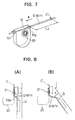
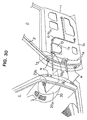
- FIGS. 1 to 8 show a first embodiment in which a door harness D ⁇ W/H is arranged in a door hinge portion between a door D and a body C of a vehicle while extending from a front end surface 1a of a door panel 1 to the body C.
- a front part of the door harness D ⁇ W/H arranged in the door hinge portion is or can be pulled toward the body C.
- this front part is inserted or fitted into an instrument panel 20 through an opening 20b formed in a side surface of the instrument panel 20 toward the door D, and is secured or fixed to an inner surface of the instrument panel 20 by a clamp 21 as shown in FIG. 8.
- the container casing 10 acts as a so-called harness spool, and is comprised of a main body 10a and a lid 10b which are integrally or unitarily formed e.g. of resin.
- the main body 10a and the lid 10b are connected via a thin hinge 10c.
- the container casing 10 has a thin box shape having a substantially semicircular cross section which defines a hollow portion 10d in which the door harness D ⁇ W/H is slidable or insertable.
- a curved side wall 10e In the main body 10a of the container casing 10, the opposite ends of a curved side wall 10e are cut away to form an insertion opening 10f and a dispensing or withdrawal opening 10g for the wiring harness which are opposed to each other, and a harness fixing portion 10h preferably projects from the edge of the outer surface at the insertion opening 10f. Further, a cylindrical projection 10k is provided at a bottom portion 10j. A lock portion having a lock hole 10m is provided at or on the leading end of the lid 10b, and a lock claw 10n is provided in such a position of the side surface of the main body 10a to be engageable or interact with the lock hole 10m when the lid 10b is closed.
- a windup spring 30 is mounted such that its central end is inserted and locked in a lock groove 10k-1 formed in the projection 10k, and is wound around the projection 10k preferably a plurality of times.
- the windup spring 30 is so biased that its outermost portion 30a expands to a position where it extends along the inner surface of the side wall 10e while defining a harness insertion space 10p therewith.
- the windup spring 30 expandably returns to its original position at a faster speed than a closing speed of the door when it is pulled back into the casing 10 after the door harness D ⁇ W/H is pulled out.
- the door harness D ⁇ W/H is inserted through the insertion opening 10f, and is secured to the harness fixing portion 10h by tape 12, a clamp, a strip or the like fixing means at the entrance of the insertion opening 10f.
- the door harness D ⁇ W/H is pulled out through the withdrawal opening 10g.
- the door harness D ⁇ W/H is looped with such a large diameter as to extend along the inner surface of the side wall 10e through the space 10p.
- the lid 10b is closed to engage the lock claw 10n with the lock hole 10m.
- a weatherstrip 2 is mounted in a position more toward a passenger compartment than a hinge or hinge coupled portion H with the body C as shown in FIG. 1
- a notch 1g for the insertion of the door harness D ⁇ W/H is formed in a corner portion between the end surface 1a and an inner plate 1h of the door panel 1 which is located more toward the passenger compartment than the mount position of the weatherstrip 2, and a recess 1k in communication with the notch 1g is formed in the inner plate 1h.
- the container casing 10 is preferably tightly fitted in the recess 1k.
- the door harness D ⁇ W/H having its front part inserted through the container casing 10 as shown in FIG. 6 is arranged along the inner surface of the inner plate 1h of the door panel 1.
- the container casing 10 is fitted in the recess 1k. In this state, the inner plate 1h is covered by a trim panel (not shown) to fix the container casing 10 inside the door D.
- the door harness D ⁇ W/H withdrawn or dispensed from the container casing 10 through the dispensing or withdrawal opening 10g is extended to the body C and, as described above, is secured to the inner surface of the instrument panel 20 by the clamp 21 after being inserted through the opening 20b formed in the side surface 20a of the instrument panel 20.
- the mount state shown in FIG. 6 is obtained when the door D is closed.
- the length of the door harness D ⁇ W/H from the container casing 10 mounted on the door D to the position where it is secured to the body C is L1 and the length thereof looped inside the container casing 10 is a margin length.
- the door harness D ⁇ W/H needs to extend while twisting or extending substantially spiral-like according an opening angle of the door D when the door D is opened.
- the door harness D ⁇ W/H needs to contract while untwisting when the door D is closed.
- the door harness D ⁇ W/H inside the container casing 10 is withdrawn through the withdrawal opening 10g while making the diameter of the loop of the door harness D ⁇ W/H smaller against the spring force of the windup spring 30.
- the length of the door harness D ⁇ W/H from the container casing 10 to the clamp 21 is extended to L2 as shown in FIGS. 7 and 8(B).
- the door harness D ⁇ W/H is withdrawn from the container casing 10 by a difference (L2-L1) between the lengths L2 and L1.
- the door harness D ⁇ W/H is wound around the windup spring 30 which is tightly wound around the projection 10k for stopping the withdrawal of the door harness D ⁇ W/H with a reduced diameter, thereby preventing any further withdrawal of the door harness D ⁇ W/H lest the withdrawn door harness D ⁇ W/H should slacken between the door D and the body C.
- the door harness D ⁇ W/H extends, following the opening movement of the door D.
- the door harness D ⁇ W/H withdrawn from the container casing 10 can twist itself and, accordingly, it can extend while twisting or curving.
- the windup spring 30 around which the door harness D ⁇ W/H is wound has a self-restoring or elastic property of substantially returning to its original shape
- the door harness D ⁇ W/H is returned in a direction R (FIG. 7) into the container casing 10 or contracted at a speed preferably faster than the closing speed of the door D due to the restoring force of the windup spring 30 while making the diameter of the loop larger. Consequently, the door harness D ⁇ W/H returns to the state of FIG. 6. Since the door harness D ⁇ W/H smoothly contracts, it can follow the closing movement of the door D and the jamming of the door harness D ⁇ W/H between the door D and the body C can be prevented.
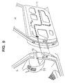
- FIGS. 9, 10(A) and 10(B) show a second embodiment, in which a container casing 10 is fixed to the inner surface of a side wall 20a of an instrument panel 20 of a body C toward a door D.
- the container casing 10 is fixed inside the instrument panel 20, and the door harness D ⁇ W/H extending from the door D is passed through the container casing 10.
- the door harness D ⁇ W/H is fixed to the inner surface of an inner plate 1h by a clamp 21'.
- an IP harness may be passed through the container casing 10; extended toward the door D and connected with the door harness D ⁇ W/H by a connector after being secured to the door D by a clamp.
- the action of the second embodiment is similar to that of the first embodiment.
- the door harness D ⁇ W/H extends while twisting as shown in FIG. 10(B), following the opening movement of the door D.
- the windup spring 30 around which the door harness D ⁇ W/H is wound returns to the state of FIG. 10(A) and, at the same time, the door harness D ⁇ W/H is pressed by the door D being closed and contractibly returned into the container casing 10 while making the diameter of the loop larger.
- an arcuate spring piece 30' is mounted such that its central end is inserted and locked in a lock groove 10k-1 formed in the projection 10k, and is arranged in an arcuate manner about the projection 10k a plurality of times.
- the spring piece 30' is so biased that its outer portion 30'a expands to a position where it extends along the inner surface of the side wall 10e while defining a harness insertion space 10p therewith.
- the spring piece 30' expandably returns to its original position at a faster speed than a closing speed of the door when it is pulled back into the casing 10 after the door harness D ⁇ W/H is pulled out. Further, the leading end 30'a of the arcuate spring piece 30' is thinned.
- the door harness D ⁇ W/H inside the container casing 10 curves the spring piece 30' against the spring force of the spring piece 30' and is withdrawn through the withdrawal opening 10g while making the diameter of the loop of the door harness D ⁇ W/H smaller.
- the leading end 30'a of the spring piece 30' is thinned, it can smoothly follow the movement of the door harness D ⁇ W/H and does not damage the door harness D ⁇ W/H.
- the length of the door harness D ⁇ W/H from the container casing 10 to the clamp 21 is extended to L2 as shown in FIGS. 17 and 8(B).
- the door harness D ⁇ W/H is withdrawn from the container casing 10 by a difference (L2-L1) between the lengths L2 and L1.
- the door harness D ⁇ W/H is wound around the spring piece 30' which is mounted on the projection 10k for stopping the withdrawal of the door harness D ⁇ W/H with a reduced diameter, thereby preventing any further withdrawal of the door harness D ⁇ W/H lest the withdrawn door harness D ⁇ W/H should slacken between the door D and the body C.
- the door harness D ⁇ W/H extends, following the opening movement of the door D.
- the door harness D ⁇ W/H withdrawn from the container casing 10 can twist itself and, accordingly, it can extend while twisting.
- the door harness D ⁇ W/H Since the spring piece 30' around which the door harness D ⁇ W/H is wound has a spring force for returning to its original shape, when the door D is moved in its closing direction, the door harness D ⁇ W/H is returned into the container casing 10 at a speed faster than the closing speed of the door D due to the restoring force of the spring piece 30' while making the diameter of the loop larger. Consequently, the door harness D ⁇ W/H returns to the state of FIG. 6. At this time as well, the door harness D ⁇ W/H can be returned without being damaged due to the thinned leading end 30'a of the spring piece 30'. Since the door harness D ⁇ W/H smoothly contracts, it can follow the closing movement of the door D and the jamming of the door harness D ⁇ W/H between the door D and the body C can be prevented.
- FIGS. 18 to 24 Those elements same or similar as those of the preceding embodiments are denoted with same or similar reference signs and accordingly a description thereof will be omitted hereinafter.
- the door harness D ⁇ W/H is inserted through the insertion opening 10f, and is secured to the harness fixing portion 10h by tape 12 at the entrance of the insertion opening 10f.
- the door harness D ⁇ W/H is pulled out through the withdrawal opening 10g.
- the door harness D ⁇ W/H is looped with a large diameter so as to substantially extend along the inner surface of the curved side wall 10e, and is preferably trained to be looped with this large diameter.
- the pull-back means 130 for producing a basing force in a pull-back direction against the withdrawal of the door harness D ⁇ W/H accommodated in the container casing 10.
- the pull-back means 130 is comprised of a spring seat 130a mounted on or fixed to the outer surface of the door harness D ⁇ W/H and a spring 130b slidably mounted on the door harness D ⁇ W/H along its length.
- the spring 130b is preferably provided in a precompressed manner between the spring seat 130a and the inner wall of the withdrawal opening 10g of the container casing 10.
- the spring seat 130a is an integral or unitary assembly of a tubular fixing portion 130c secured to the outer surface of the door harness D ⁇ W/H by a fixing means such as tape and a flange-shaped receiving portion 130d.
- a fixing means such as tape
- One end of the spring 130b is engaged with a lock hole 130e formed in the fixing portion 130c.
- the other end of the spring 130b is engaged with a hook 130f projecting from the inner wall of the withdrawal opening 10g.
- the opposite ends of the spring 130b are not necessarily lockingly fixed, it is preferable to prevent the generation of unpleasant sounds caused by the vibration of an automotive vehicle or the like.
- a mount position of the spring seat 130a to the door harness D ⁇ W/H is a position spaced from the withdrawal opening 10g preferably by longer than a length the door harness D ⁇ W/H is withdrawn or dispensed as the door D is opened in consideration of the extension and contraction of the spring 130b. Accordingly, when the door harness D ⁇ W/H is withdrawn from the withdrawal opening 10g as the door D is opened, the spring 130b is compressed between the spring seat 130a and the dispensing or withdrawal opening 10g, producing a basing force for pulling the door harness D ⁇ W/H back.
- the lid 10b is substantially closed to engage the lock claw 10n and the lock hole 10m.
- the door harness D ⁇ W/H to be accommodated in the container casing 10 may be covered by a tube 11 the opposite ends of which are fixed by tapes 13 as shown in FIG. 24 in order to protect the other surface of the door harness D ⁇ W/H.
- the tube 11 is made of e.g. a nylon tube having a specified thickness and has a smooth outer surface, it can smoothly move in the container casing 10.
- the door harness D ⁇ W/H may be trained to be looped with a large diameter so as to have a self-restoring property of returning to its original shape of FIG. 22 when a pulling force is released with the door harness D ⁇ W/H withdrawn as shown in FIG. 23. This training helps the basing force of the spring 130b in pulling the door harness D ⁇ W/H back. Further, by being covered with the tube 11, the sliding movement of the door harness D ⁇ W/H inside the container casing 10 does not cause abrasion or friction of the coating thereof.
- the door harness D ⁇ W/H inside the container casing 10 is withdrawn through the dispensing or withdrawal opening 10g against the direction R (FIG. 23) while making the diameter of the loop of the door harness D ⁇ W/H smaller.
- the length of the door harness D ⁇ W/H from the container casing 10 to the clamp 21 is extended in the direction R to L2 as shown in FIGS. 23 and 8(B).
- the door harness D ⁇ W/H is withdrawn from the container casing 10 by a difference (L2-L1) between the lengths L2 and L1.
- the door harness D ⁇ W/H is wound around the projection 10k for stopping the withdrawal of the door harness D ⁇ W/H, thereby preventing any further withdrawal of the door harness D ⁇ W/H lest the withdrawn door harness D ⁇ W/H should slacken between the door D and the body C.
- the door harness D ⁇ W/H extends, following the opening movement of the door D.
- the door harness D ⁇ W/H withdrawn from the container casing 10 can twist itself and, accordingly, it can extend while twisting.
- a basing force of the compressed spring 130b acts on the door harness D ⁇ W/H in the pull-back direction R in the container casing 10. Accordingly, when the door D is moved in a closing direction, the door harness D ⁇ W/H is returned into the container casing 10 at a speed preferably faster than a closing speed of the door D due to the restoring force of the spring 130b while making the diameter of the loop larger. Consequently, the door harness D ⁇ W/H returns to the state of FIG. 22(A). Since the door harness D ⁇ W/H smoothly contracts, it can follow the closing movement of the door D and the jamming of the door harness D ⁇ W/H between the door D and the body C can be prevented.
- FIGS. 25 to 27 Same or similar elements as those in the previous embodiments are denoted with the same or similar reference numerals and accordingly a description thereof will be omitted hereinafter.
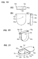
- a substantially bar-shaped auxiliary member 230 having preferably a round cross section is made of a flexible and linear elastic member or material as shown in FIG. 25(A) and is integrally assembled with a part of the door harness D ⁇ W/H to be accommodated in the container casing 10 e.g. by being located at the axial center of a wire bundle W of the door harness D ⁇ W/H and by being fixed in suitable intermediate positions by tapes 230a as shown in FIG. 25(B).
- the door harness D ⁇ W/H having the auxiliary member 230 arranged preferably at its axial center is inserted into the container casing 10 through the insertion opening 10f as shown in FIG.
- the auxiliary member 230 is flexible or elastic preferably in a direction other than the longitudinal direction thereof. In other words, the auxiliary member 230 has a tendency to restore its original shape (e.g. the substantially bar-shaped shape) upon a deflection at one or more positions in a radial direction thereof.
- the door harness D ⁇ W/H is withdrawn through the dispensing or withdrawal opening 10f after being looped at least once together with the auxiliary member 230 to substantially surround the projection 10k against the elastic force as shown in FIG. 26.
- the door harness D ⁇ W/H is looped with such a large diameter that it extends substantially along the inner surface of the curved side wall 10e, so that the elastic restoring force of the auxiliary member 230 causes a basing force to act on the door harness D ⁇ W/H in a pull-back direction R in which the door harness D ⁇ W/H is pulled back into the container casing 10.
- the lid 10b is closed to engage the lock hole 10m and the lock claw 10n.
- the bar-shaped auxiliary member 230 may be arranged not only at the axial center of the door harness D ⁇ W/H, but also at a radially more outward position, e.g. along the substantially outer surface thereof.
- a weatherstrip 2 is mounted in a position more toward a passenger compartment than a hinge H with the body C (as shown e.g. in FIG. 1).
- a notch 1g for the insertion of the door harness D ⁇ W/H is formed in a corner portion between the end surface 1a and an inner plate 1h of the door panel 1 which is located more toward the passenger compartment than the mount position of the weatherstrip 2, and a recess 1k in communication with the notch 1g is formed in the inner plate 1h.
- the container casing 10 is tightly fitted in the recess 1k.
- the elastic restoring force of the auxiliary member 230 is causing the basing force to act on the door harness D ⁇ W/H in the pull-back direction R inside the container casing 10. Accordingly, when the door D is moved in its closing direction, the door harness D ⁇ W/H is returned into the container casing 10 at a speed preferably faster than the closing speed of the door D while making the diameter of the loop larger. Consequently, the door harness D ⁇ W/H returns to the state of FIG. 26. Since the door harness D ⁇ W/H smoothly contracts, it can follow the closing movement of the door D and the jamming of the door harness D ⁇ W/H between the door D and the body C can be prevented.
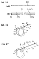
- FIGS. 28(A) to 28(C) show a sixth embodiment, in which an auxiliary member 240 for causing a biasing force to act on the door harness D ⁇ W/H in the pull-back direction into the container casing 10 is a substantially flat plate member made of a flexible elastic member.
- the auxiliary member 240 is arranged substantially along the outer surface of the door harness D ⁇ W/H and integrally assembled therewith by being fixed in opposite end positions and suitable intermediate position(s) by tapes 240a.
- the auxiliary member 240 is accommodated together with the door harness D ⁇ W/H in the container casing 10 after being looped at least once.
- the returning action of the door harness D ⁇ W/H by the restoring force of the auxiliary member 240 when the door D is closed is similar to the fifth embodiment.
- FIGS. 29(A) to 29(C) show a seventh embodiment, in which an auxiliary member 250 for causing a biasing force to act on the door harness D ⁇ W/H in the pull-back direction into the container casing 10 is a gutterlike member having a substantially C-shaped cross section and made of a flexible elastic member or material.
- An inner diameter d2 of the auxiliary member 250 is set larger than a width d1 of a gutter portion 250c so that the door harness D ⁇ W/H can be enclosed in the gutter portion 250c.
- the auxiliary member 250 is fitted along the outer surface of the door harness D ⁇ W/H, and is fixed to taping portions 250b projecting from the opposite ends of the auxiliary member 250 by tapes 250d.
- the auxiliary member 250 is accommodated together with the door harness D ⁇ W/H in the container casing 10 after being looped once with the gutter portion 250c faced outward.
- the auxiliary member 250 may be made at least partially of a corrugated member in order to improve its bending property.
- the auxiliary member may be formed by casting or immersing at least a portion of the wiring harness with or in a casting material being resilient, in particular in its cured state, and having the self-restoring properties like or similar to the auxiliary members according to the preceding embodiments.
- FIGS. 30 to 35 show a eighth embodiment in which a door harness D ⁇ W/H is arranged in a door hinge portion between a door D and a body C of a vehicle while extending from a front end surface 1a of a door panel 1 to the body C.
- a front part of the door harness D ⁇ W/H arranged in the door hinge portion is pulled toward the body C.
- this front part is inserted into an instrument panel 20 through an opening 20a formed in a side surface of the instrument panel 20 toward the door D, and is secured to an inner surface of the instrument panel 20 by a clamp 21 as shown in FIG. 8.
- the container casing 10 has a substantially semicircular shape and acts as a so-called harness spool.
- the container casing 10 is comprised of a main body 410a and a side plate portion 410e to be mounted on the main body 410a after the door harness D ⁇ W/H is passed through the container casing 10.
- the main body 410a and the side plate portion 410e are both made e.g. of resin.
- the main body 410a includes a substantially semicircular bottom plate 410c, a lid 410b and a connecting plate 410d which is a flat plate for connecting substantially linear parts of the bottom plate 410c and of the lid 410b.
- a cylindrical stopper projection 410k projects from the bottom plate 410c in a space defined between the bottom plate 410c and the lid 410b.
- a harness fixing portion 410h projects preferably outward at one end of the periphery of the bottom plate 410c abutting on the connecting plate 410d.
- the container casing 10 has a lateral opening 410i, i.e. an opening 410i being arranged at a side of the container casing 10, in which the wiring harness D ⁇ W/H is substantially bent (to be preferably looped).
- the side plate portion 410e can substantially close the opening 410i.
- the side plate portion 410e has preferably a substantially semicircular shape so as to substantially close an arcuate opening defined between the bottom plate 410c and the lid 410b.
- Lock claws or projections 410m are formed at the leading ends of the substantially opposite sides of the side plate portion 410e and at the opposite widthwise sides of the apex thereof.
- the lock claws 410m are inserted into lock holes or recesses of lock portions 410n formed in corresponding positions of the main body 410a to effect locking.
- notches are formed at the opposite ends of the side plate portion 410e so as to define an insertion opening 10f and a dispensing or withdrawal opening 10g for the harness together with the connecting plate 410d with the side plate portion fixed to the main body 410a.
- the insertion and withdrawal openings 10f, 10g are not at the same position, but are displaced along the widthwise direction.
- the insertion hole 10f and/or the dispensing or withdrawal hole 10g are formed or defined by recesses 10e-1 and/or 10e-2 in cooperation with the plates 410c, 410d. Accordingly, the opening 410i substantially extends preferably from the position of the insertion opening 10f to the dispensing or withdrawal opening 10g.
- the door harness D ⁇ W/H covered by a tube 411 the opposite ends of which are fixed by fixing means, in particular tapes 13 as shown in FIG. 33.
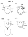
- the door harness D ⁇ W/H is inserted through the side opening 410i of the main body 410a as shown in FIGS. 34(A) to 34(D) before the side plate portion 410c is mounted.
- one side S1 of the door harness D ⁇ W/H is inserted through a clearance between the projection 410k and the connecting plate 410a as shown in FIG. 34(A).
- the other side S2 is passed between the projection 410k and the connecting plate 410c as shown in FIG. 34(B).
- the diameter of the loop of the door harness D ⁇ W/H is made smaller by pulling the portions of the door harness D ⁇ W/H projecting outward from the opposite sides of the main body 410a so that the looped portion can be substantially located inside the main body 410a as shown in FIG. 34(C).
- the side plate portion 410e is mounted on and locked with the main body 410a as shown in FIG. 34(D).
- the door harness D ⁇ W/H is then fixed to the harness fixing portion 410h by tape 12 at the entrance portion of the insertion opening 10f.
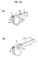
- the door harness D ⁇ W/H is withdrawn through the withdrawal opening 10g after being looped once around the projection 410k inside the container casing 10 as shown in FIGS. 35(A) and 35(B). At this time, the door harness D ⁇ W/H is looped with a large diameter so as to extend along the inner surface of the curved side wall 410e, and is trained to be looped with this large diameter. In this way, the door harness D ⁇ W/H is passed through the container casing 10 while providing a margin length.
- the tube 411 is made e.g. of a nylon tube having a specified thickness and has a smooth outer surface, it can smoothly move in the container casing 10.
- the door harness D ⁇ W/H may be trained to be looped with a large diameter so as to have a self-restoring property of returning to its original shape of FIG. 35(A) when a pulling force is released with the door harness D ⁇ W/H withdrawn as shown in FIG. 35(B). This training helps the biasing force of the spring 30b in pulling the door harness D ⁇ W/H back. Further, by being covered with the tube 411, the sliding movement of the door harness D ⁇ W/H inside the container casing 10 does not cause abrasion of the coating thereof.
- a weatherstrip 2 is mounted in a position more toward a passenger compartment than a hinge H with the body C as shown in FIG. 30.
- a notch 1g for the insertion of the door harness D ⁇ W/H is formed in a corner portion between the end surface 1a and an inner plate 1h of the door panel 1 which is located more toward the passenger compartment than the mount position of the weatherstrip 2, and a recess 1k in communication with the notch 1g is formed in the inner plate 1h.
- the container casing 10 is tightly fitted in the recess 1k.
- the door harness D ⁇ W/H having its front part inserted through the container casing 10 as shown in FIGS. 35(A) and 35(B) is arranged along the inner surface of the inner plate 1h of the door panel 1.
- the container casing 10 is fitted in the recess 1k. In this state, the inner plate 1h is covered by a trim panel (not shown) to fix the container casing 10 inside the door D.
- the door harness D ⁇ W/H withdrawn from the container casing 10 through the withdrawal opening 10g is extended to the body C and, as described above, is secured to the inner surface of the instrument panel 20 by the clamp 21 after being inserted through the opening 20b formed in the side surface 20a of the instrument panel 20.
- the mount state shown in FIG. 35(A) is obtained when the door D is closed.
- the length of the door harness D ⁇ W/H from the container casing 10 mounted on the door D to the position where it is secured to the body C is L1 and the length thereof looped inside the container casing 10 is a margin length.
- the door harness D ⁇ W/H needs to extend while twisting according an opening angle of the door D when the door D is opened.
- the door harness D ⁇ W/H needs to contract while untwisting when the door D is closed.
- the door harness D ⁇ W/H inside the container casing 10 is withdrawn through the withdrawal opening 10g while making the diameter of the loop of the door harness D ⁇ W/H smaller against the spring force of the windup spring 30.
- the length of the door harness D ⁇ W/H from the container casing 10 to the clamp 21 is extended to L2 as shown in FIGS. 35(B) and 8(B).
- the door harness D ⁇ W/H is withdrawn from the container casing 10 by a difference (L2-L1) between the lengths L2 and L1.
- the door harness D ⁇ W/H is wound around the windup spring 30 which is tightly wound around the projection 410k for stopping the withdrawal of the door harness D ⁇ W/H with a reduced diameter, thereby preventing any further withdrawal of the door harness D ⁇ W/H lest the withdrawn door harness D ⁇ W/H should slacken between the door D and the body C.
- the door harness D ⁇ W/H extends, following the opening movement of the door D.
- the door harness D ⁇ W/H withdrawn from the container casing 10 can twist itself and, accordingly, it can extend while twisting.
- the tube 411 covering the door harness D ⁇ W/H has a self-restoring property of returning to its original shape. Accordingly, when the door D is closed in its opened state, the door harness D ⁇ W/H is returned into the container casing 10 by the restoring force of the tube 411 at a speed preferably faster than a closing speed of the door D while making the diameter of the loop larger. Consequently, the door harness D ⁇ W/H returns to the state of FIG. 35(A). Since the door harness D ⁇ W/H smoothly contracts, it can follow the closing movement of the door D and the jamming of the door harness D ⁇ W/H between the door D and the body C can be prevented.
- FIGS. 36(A) and 36(B) is shown a ninth embodiment of the invention.
- the embodiment is substantially similar to the eight embodiment and similar or same parts are denoted with similar or same reference numerals. Accordingly a description thereof will be omitted hereinafter.
- the ninth embodiment further comprises a pull-back means 130, preferably in the form of a helicoidal spring, which has already been described with reference to the fourth embodiment (FIGS. 22 and 23). Accordingly reference is made to the according above description.
- FIGS. 37, 38(A) to 38(D) show a tenth embodiment of the invention, in which a separate projection member 410k' which acts as the projection 410k provided in the container casing 10 is mounted later.
- a lid 410b of a main body 410a is formed with a mount hole 410b-1.
- the projection member 410k' is inserted or insertable into the mount hole 410b-1 and fixed by the engagement of a large diameter portion 410k'-1 provided at the leading end of the projection member 410k' and the lid 410b.
- the door harness D ⁇ W/H can be inserted through the side opening of the main body 410a after being looped at least once and the projection member 410k' can be mounted after being positioned inside the loop of the door harness D ⁇ W/H as shown in FIGS. 38(A) to 38(D). Accordingly, the door harness D ⁇ W/H can be easily mounted. After the door harness D ⁇ W/H is inserted into the main body 410a, the side plate portion 410e is mounted and locked similar to the eighth embodiment.
- the eighth to tenth embodiment may be arranged like the second embodiment described with reference to FIGS. 8 to 10. Accordingly reference is made to the above description.
- the present invention is not limited to the foregoing embodiments.
- the insertion and withdrawal openings of the container casing may be formed at different stages and the bottom surface of the container casing may be slanted.
- portions of the harness inside the container casing do not directly cross each other, i.e. do not touch each other and, accordingly, the harness can be looped without being entangled.
- the wiring harness to be arranged between the door and the body of the vehicle is arranged not in the same position as the hinge position, but in the position more inward toward the passenger compartment. Accordingly, the wiring harness is required to have both an extendible/contractible function and a twisting or bending function when the door is opened and closed. Since the container casing having a function of extending and contracting the wiring harness is provided, the wiring harness can extend and contract as the door is opened and closed. Further, since the wiring harness withdrawn from the container casing can twist itself, it can smoothly follow the opening and closing movements of the door.
- the wiring harness inside the container casing is biased by the pull-back or basing means, e.g. the windup spring in such a direction as to be returned into the container casing or so as to be contracted, it can be returned into the container casing faster than the closing speed of the door when the door is closed.
- the pull-back or basing means e.g. the windup spring in such a direction as to be returned into the container casing or so as to be contracted
- the container casing Since the container casing has such a small configuration which only accommodates the wiring harness in a looped state, it can be mounted in a small space. Further, since the container casing is not very much exposed to the passenger compartment, it does not degrade the appearance. Even if the container casing is mounted on the door, since it is small and lightweight, the mounting of the container casing does not require an increased force to open and close the door, i.e. does not make the door heavier to open and close.
- the wiring harness is arranged or arrangeable in a position more inward than the hinge position and the weatherstrip, it is not necessary to provide a water preventing means for the wiring harness, obviating the need to use grommets or like conventional water preventing devices.
- the wiring harness is arranged at the side of the inner surface of the inner Plate of the door panel, a conventionally required operation of arranging the wiring harness inside the door panel and withdrawing it through the through hole formed in the front end surface of the door panel can be eliminated. As a result, an operation of arranging the wiring harness into the door panel can be considerably made easier as compared with the prior art.
Abstract
Description
wherein the container casing is fixed or mounted or mountable to either one or both of the first and second elements, in particular of the door and the vehicle body, and the wiring harness dispensed or withdrawn from the container casing is extended to the other of the first and second elements, in particular of the door and the vehicle body, so that the wiring harness inside the container casing extends and contracts according to the movement and/or rotation of the first and second elements with respect to each other, in particular as the door is opened and closed.
wherein the wiring harness is returned or pulled-back into the container casing by a biasing force of the windup spring to make its diameter larger.
wherein the container casing is fixed to either one of the door and the vehicle body and the wiring harness withdrawn from the container casing is extended to the other of the door and the vehicle body and secured thereto by a clamp, so that the wiring harness inside the container casing is withdrawn while making the diameter of the windup spring smaller as the door is opened, and is returned into the container casing by a biasing force of the windup spring to make its diameter larger when the door is closed, thereby extending and contracting as the door is opened and closed.
wherein the wiring harness inside the container casing is dispensed against a biasing force of the spring piece and is pulled-back or returned into the container casing by the biasing force of the spring piece.
wherein the container casing is fixed to either one of the door and the vehicle body and the wiring harness withdrawn from the container casing is extended to the other of the door and the vehicle body and secured thereto by a clamp, so that the wiring harness inside the container casing is withdrawn against the biasing force of the spring piece as the door is opened, and is returned into the container casing by the biasing force of the spring piece when the door is closed, thereby permitting the wiring harness to extend and contract as the door is opened and closed.
wherein the container casing is fixed to either one of the door and the vehicle body and the wiring harness withdrawn from the container casing is extended to the other of the door and the vehicle body and secured thereto by a clamp, so that the wiring harness inside the container casing extends and contracts as the door is opened and closed while varying the diameter of the loop thereof.
wherein the container casing is fixed to either one of the door and the vehicle body and the wiring harness withdrawn from the container casing is extended to the other of the door and the vehicle body and secured thereto by a clamp, so that the wiring harness inside the container casing changes a diameter of its loop as the door is opened and closed, thereby extending and contracting to follow the movement of the door.
wherein:
wherein:
- C
- Body
- D
- Door
- D·W/H
- Door Harness
- H
- Hinge
- 1
- Door Panel
- 1a
- End Surface
- 1k
- Recess
- 2
- Weatherstrip
- 10
- Container Casing
- 10a
- Main Body
- 10b
- Lid
- 10f
- Insertion Opening
- 10g
- Withdrawal Opening
- 10h
- Harness Fixing Portion
- 10k
- Projection
- 20
- Instrument Panel
- 30
- Windup Spring
- 30'
- Arcuate Spring Piece
- 130
- Pull-Back Means
- 130a
- Spring Seat
- 130b
- Spring
- 230, 240, 250
- Auxiliary Member
- 230a, 240a, 250a
- Tape
- 410a
- Main Body
- 410b
- Lid
- 410c
- Bottom Plate
- 410d
- Connecting Plate
- 10f
- Insertion Opening
- 10g
- Withdrawal Opening
- 410h
- Harness Fixing Portion
- 410i
- Side Opening
- 410k
- Projection
- 410k'
- Projection
Claims (17)
- A wiring harness arranging construction for arranging a wiring harness (D·W/H) to be arranged between a first element (C) and a second element (D) being movable and/or rotatable with respect to each other, in particular between a vehicle body (C) and a door (D) in a position more toward a passenger compartment than a mount position of a hinge (H) for connecting the vehicle body (C) and the door (D) and preferably a weatherstrip (2), comprising:at least one container casing (10) comprising a hollow portion for accommodating a portion of the wiring harness (D·W/H), an insertion opening (10f) and a dispensing or withdrawal opening (10g) for the wiring harness (D·W/H) ,, anda pull-back means (30; 30'; 111; 130; 230; 240; 250; 411) for producing a basing force in a direction (R) in which the wiring harness (D·W/H) is pulled back into the container casing (10) as the wiring harness (D·W/H) is dispensed or withdrawn,, and
wherein the container casing (10) is fixed or mountable to either one or both of the first and second elements (C; D), in particular of the door (D) and the vehicle body (C), and the wiring harness (D·W/H) dispensed or withdrawn from the container casing (10) is extended to the other of the first and second elements (C; D), in particular of the door (D) and the vehicle body (C) , so that the wiring harness (D·W/H) inside the container casing (10) extends and contracts according to the movement and/or rotation of the first and second elements (C; D) with respect to each other, in particular as the door (D) is opened and closed. - A wiring harness arranging construction according to claim 1, wherein the wiring harness (D·W/H) is looped at least once inside the container casing (10) between the dispensing opening (10g) and the insertion opening (10f), and wherein the wiring harness (D·W/H) inside the container casing (10) extends and contracts according to the movement and/or rotation of the first and second elements (C; D) with respect to each other, in particular as the door (D) is opened and closed, while varying the diameter of the loop(s) thereof.
- A wiring harness arranging construction according to one or more of the preceding claims, whereinthe pull-back means (30; 30'; 111; 130; 230; 240; 250; 411) comprises a windup spring (30) which is mounted on the container casing (10), preferably wound around a stopper projection (10k), which projects into the space inside the container casing (10), after having a center end thereof secured to the stopper projection (10k), and is biased such that an outermost portion thereof substantially extends toward or along the inner surface (10e) of the container casing (10) in its expanded state while defining a harness insertion space (10p) with the inner surface (10e) of the container casing (10), the wiring harness (D·W/H) being passed through the container casing (10) by being inserted through the insertion opening (10f) and dispensed through the dispensing opening (10g) after being passed, preferably looped at least once, along the outer surface of the windup spring (30) inside the harness insertion space (10p),
wherein the wiring harness (D·W/H)is returned or pulled-back into the container casing (10) by a biasing force of the windup spring (30) to make its diameter larger. - A wiring harness (D·W/H) arranging construction according to one or more of the preceding claims, wherein the pull-back means (30; 30'; 111; 130; 230; 240; 250; 411) comprisesa substantially arcuate spring piece (30') which has one end thereof secured to the container casing (10), preferably a stopper projection (10k) arranged inside thereof, and is biased such that an outer portion thereof extends toward or along an inner surface (10e) of the container casing (10) in its expanded state while defining a harness insertion space (10p) with the inner surface (10e) of the container casing (10), the wiring harness (D·W/H) being passed through the container casing (10) by being inserted through the insertion opening (10f) and dispensed through the dispensing opening (10g) after passing, preferably being looped at least once, along the outer surface of the spring piece (30') inside the harness insertion space (10p),
whereinthe wiring harness (D·W/H) inside the container casing (10) is dispensed against a basing force of the spring piece (30') and is pulled-back or returned into the container casing (10) by the basing force of the spring piece (30'). - A wiring harness arranging construction according to claim 4, wherein the leading end of the arcuate spring piece (30') is thinned so as not to exert a load on the wiring harness (D·W/H).
- A wiring harness arranging construction according to one or more of the preceding claims, wherein the pull-back means (30; 30'; 111; 130; 230; 240; 250; 411) comprises a spring seat (30'a) mounted on the wiring harness (D·W/H), preferably on the outer surface thereof, and a spring (30'b) mounted on the wiring harness (D·W/H) between the spring seat (30'a) and the dispensing opening (10g) of the container casing (10).
- A wiring harness arranging construction according to one or more of the preceding claims, further comprising a stopper projection (10k) provided inside the container casing (10), wherein the wiring harness (D·W/H) is preferably accommodated with looped at least once around the projection (10k), so that the dispensing of the wiring harness (D·W/H) is stopped with the wiring harness (D·W/H) wound around the stopper projection (10k) when the wiring harness (D·W/H) is dispensed from the container casing (10) by a length more than a predetermined or predeterminable length (L2).
- A wiring harness arranging construction according to one or more of the preceding claims and claim 2, wherein the pull-back means (30; 30'; 111; 130; 230; 240; 250; 411) comprises a tube (111; 411), formed preferably of nylon, being arranged on a portion of the wiring harness (D·W/H), preferably a looped portion thereof, inside the container casing (10) and being trained to be looped with a large diameter so as to have a self-restoring property of returning substantially to its original shape, when a dispensing or withdrawing force acting on the wiring harness (D·W/H) is released.
- A wiring harness arranging construction according to one or more of the preceding claims, wherein the pull-back means (30; 30'; 111; 130; 230; 240; 250; 411) comprisesan auxiliary member (230; 240; 250; 411) made of a flexible and substantially linear elastic member or material which is integrally or unitary assembled with a portion of the wiring harness (D·W/H) to be accommodated in the container casing (10), preferably so as to be located along the looped portion of the wiring harness (D·W/H), the restoring force of the auxiliary member (230; 240; 250; 411) causing a biasing force to act on the wiring harness (D·W/H) in a pull-back direction (R) into the container casing (10).
- A wiring harness arranging construction according to claim 9, wherein the auxiliary member (230; 240; 250) comprises a substantially bar-shaped member (230), which is preferably arranged substantially along the axial center and/or the outer surface of the wiring harness (D·W/H) within the container casing (10) and has at least the substantially opposite ends thereof fixed to the wiring harness (D·W/H) by holding means (230a), e.g. by taping.
- A wiring harness arranging construction according to claim 9 or 10, wherein the auxiliary member (230; 240; 250) comprises a substantially flat plate member (240) which is arranged substantially along the outer surface of the wiring harness (D·W/H) within the container casing (10) and has at least the substantially opposite ends thereof fixed to the wiring harness (D·W/H) by holding means (240a), e.g. by taping.
- A wiring harness arranging construction according to one or more of the preceding claims 9 to 11, wherein the auxiliary member (230; 240; 250) comprises a gutterlike member (250), preferably having a substantially C-shaped cross section, which is arranged substantially along the periphery of the wiring harness (D·W/H) within the container casing (10) and has at least the opposite ends thereof fixed to the wiring harness (D·W/H) by holding means (230a), e.g. by taping.
- A wiring harness (D·W/H) arranging construction according to one or more of the preceding claims, for arranging a wiring harness (D·W/H) to be arranged between a first element (C) and a second element (D) being movable and/or rotatable with respect to each other, in particular between a vehicle body (C) and a door (D) in a position more toward a passenger compartment than a mount position of a hinge (H) for connecting the vehicle body (C) and the door (D) and preferably a weatherstrip (2), comprising:a container casing (10) comprising a main body (410a) including a bottom plate (410c), a lid (410b) and a connecting plate (410d) connecting edges of the bottom plate (410c) and the lid (410b),
wherein:the opposite sides of the wiring harness (D·W/H) are pulled out through an insertion opening (10f) and a withdrawal or dispensing opening (10g) which are opposed to the wiring harness (D·W/H) at positions on or at the side plate portion (410e) and the connecting plate (410d),the container casing (10) having an opening (410i) extending substantially from the insertion opening (10f) to the dispensing opening (10g) at a lateral side of the container casing (10), the opening (410i) being provided for the arrangement of the wiring harness (D·W/H) inside the container casing (10) and being substantially closeable by a side plate portion (410e) of the container casing (10),the container casing (10) is fixed or mountable to either one or both of the first and second elements (C; D), in particular of the door (D) and the vehicle body (C), and the wiring harness (D·W/H) dispensed or withdrawn from the container casing (10) is extended to the other of the first and second elements (C; D), in particular of the door (D) and the vehicle body (C), so that the wiring harness (D·W/H) inside the container casing (10) changes a diameter of its loop as the first and second elements (C; D) are moved and/or rotated with respect to each other, in particular as the door (D) is opened and closed, thereby extending and contracting to follow the movement and/or rotation of the first and second elements (C; D), in particular of the door (D). - A wiring harness arranging construction according to claim 13, further comprising at least one stopper projection (410k) which projects from the bottom plate (410c) of the main body (410a) inside the container casing (10), wherein the wiring harness (D·W/H) is passed through the side opening (410i) while being wound at least once around the stopper projection (410k).
- A wiring harness arranging construction according to claim 13 or 14, further comprising a projection insertion hole (410b-1) formed in the lid (410b) of the container casing (10), and a projection member (410k') insertable into the projection insertion hole (410b-1) and comprising preferably a large diameter portion (410k'-1) provided at the leading end thereof, wherein the wiring harness (D·W/H) is inserted through the side opening (410i) of the main body (410a) while being looped at least once, and the projection member (410k'-1) is inserted into the projection insertion hole (410b-1) such that it is located inside the looped portion of the wiring harness (D·W/H) and the large diameter portion (410k'-1) preferably engages the lid (410b).
- A wiring harness arranging construction according to one or more of the preceding claims 13 to 15, further comprising a harness fixing portion (410h) projecting in a position of the main body (410a), preferably of a side portion thereof, of the container casing (10) or of the insertion opening (410i) of the side plate portion (410e), wherein the harness fixing portion (410h) and the wiring harness (D·W/H) are fixed by a fixing means (412), e.g. by taping, so that the wiring harness (D·W/H) is inserted while being fixed preferably to the insertion opening (10f).
- A wiring harness arranging construction according to one or more of the preceding claims 13 to 16, wherein the insertion hole (10f) and/or the dispensing or withdrawal hole (10g) is/are formed or defined by one or more recesses (410e-1; 410e-2) formed in the side plate portion (410e) in cooperation with the bottom plate (410c), the lid (410b) and/or the connecting plate (410d).
Applications Claiming Priority (10)
| Application Number | Priority Date | Filing Date | Title |
|---|---|---|---|
| JP8345949A JPH10181472A (en) | 1996-12-25 | 1996-12-25 | Wire harness arrangement structure on door hinge part of automobile |
| JP345950/96 | 1996-12-25 | ||
| JP345949/96 | 1996-12-25 | ||
| JP34595096A JP3541593B2 (en) | 1996-12-25 | 1996-12-25 | Wiring harness routing structure for door hinges of automobiles |
| JP347066/96 | 1996-12-26 | ||
| JP8348286A JPH10181481A (en) | 1996-12-26 | 1996-12-26 | Wire harness arrangement structure in door hinge part of automobile |
| JP347067/96 | 1996-12-26 | ||
| JP34706796A JP3651153B2 (en) | 1996-12-26 | 1996-12-26 | Wire harness wiring structure in the door hinge of an automobile |
| JP8347066A JPH10181476A (en) | 1996-12-26 | 1996-12-26 | Wire harness arrangement structure in door hinge of automobile |
| JP348286/96 | 1996-12-26 |
Publications (2)
| Publication Number | Publication Date |
|---|---|
| EP0855312A2 true EP0855312A2 (en) | 1998-07-29 |
| EP0855312A3 EP0855312A3 (en) | 1999-04-07 |
Family
ID=27531282
Family Applications (1)
| Application Number | Title | Priority Date | Filing Date |
|---|---|---|---|
| EP97122966A Withdrawn EP0855312A3 (en) | 1996-12-25 | 1997-12-29 | A wiring harness arranging construction |
Country Status (3)
| Country | Link |
|---|---|
| US (2) | US5957702A (en) |
| EP (1) | EP0855312A3 (en) |
| CN (1) | CN1064184C (en) |
Cited By (9)
| Publication number | Priority date | Publication date | Assignee | Title |
|---|---|---|---|---|
| EP1241057A1 (en) * | 2001-03-16 | 2002-09-18 | Yazaki Corporation | Harness slack holding apparatus for sliding car doors |
| FR2863114A1 (en) * | 2003-10-29 | 2005-06-03 | Yazaki Corp | ELECTRICAL SUPPLY DEVICE CONTINUES |
| EP1544046A1 (en) * | 2003-12-17 | 2005-06-22 | Sumitomo Wiring Systems, Ltd. | Structure for installing a door harness |
| DE10118203B4 (en) * | 2000-04-11 | 2005-09-08 | Yazaki Corp. | Power supply arrangement |
| EP1681206A1 (en) * | 2005-01-18 | 2006-07-19 | Volkswagen Aktiengesellschaft | Device including a grommet for a communication passage between relatively movable vehicle components |
| DE102004029958B4 (en) * | 2003-06-26 | 2007-09-20 | Yazaki Corp. | Device for electrical power supply |
| EP2402217A1 (en) * | 2009-02-25 | 2012-01-04 | Yazaki Corporation | Wire harness lanyard structure |
| GB2567801A (en) * | 2017-09-05 | 2019-05-01 | Version 22 Design Ltd | Cable housing |
| EP3851331A1 (en) * | 2020-01-15 | 2021-07-21 | Yazaki Systems Technologies GmbH | Self-deploying cable harness system with a cable harness and with an actuator and method for operating such a cable harness system |
Families Citing this family (23)
| Publication number | Priority date | Publication date | Assignee | Title |
|---|---|---|---|---|
| EP1087465B1 (en) | 1999-09-27 | 2012-03-28 | Autonetworks Technologies, Ltd. | Connector |
| JP2001097141A (en) | 1999-09-29 | 2001-04-10 | Sumitomo Wiring Syst Ltd | Movable wire harness |
| JP4320961B2 (en) * | 2001-02-21 | 2009-08-26 | 住友電装株式会社 | Door harness wiring structure |
| FR2822305B1 (en) * | 2001-03-14 | 2003-09-19 | Meritor Light Vehicle Sys Ltd | GUIDING AND HOLDING DEVICE OF ELECTRICAL BEAMS |
| GB0203941D0 (en) * | 2002-02-20 | 2002-04-03 | Meritor Light Vehicle Sys Ltd | A vehicle |
| JP3782741B2 (en) * | 2002-02-22 | 2006-06-07 | 矢崎総業株式会社 | Circuit assembly structure using power supply protector for door |
| US6844497B2 (en) | 2002-03-26 | 2005-01-18 | Honda Giken Kogyo Kabushiki Kaisha | Wire harness arrangement |
| JP4047778B2 (en) * | 2003-07-30 | 2008-02-13 | 矢崎総業株式会社 | Wire surplus length absorber |
| JP4124104B2 (en) * | 2003-11-14 | 2008-07-23 | 住友電装株式会社 | Protector |
| DE102004028577A1 (en) * | 2004-06-15 | 2005-12-29 | Leoni Elocab Gmbh | Guiding device for guiding a hose |
| EP1818221B1 (en) * | 2006-02-13 | 2008-06-18 | Delphi Technologies, Inc. | Cable section |
| JP2008143235A (en) * | 2006-12-06 | 2008-06-26 | Sumitomo Wiring Syst Ltd | Wiring structure for wire harness for door |
| JP5047869B2 (en) * | 2008-04-14 | 2012-10-10 | 矢崎総業株式会社 | Grommet opening and closing device and harness insertion method using the same |
| JP5416482B2 (en) * | 2009-05-22 | 2014-02-12 | 矢崎総業株式会社 | Wire harness wiring body, wire harness wiring unit, and method of assembling wire harness wiring unit |
| JP5424468B2 (en) * | 2009-06-03 | 2014-02-26 | 矢崎総業株式会社 | Wiring harness wiring structure |
| JP2013018322A (en) | 2011-07-08 | 2013-01-31 | Sumitomo Wiring Syst Ltd | Wire harness routing structure part |
| JP6010817B2 (en) * | 2012-09-03 | 2016-10-19 | 矢崎総業株式会社 | Combined structure of wire harnesses |
| JP2015000619A (en) * | 2013-06-14 | 2015-01-05 | 住友電装株式会社 | Wiring device for door panel |
| CN106384980B (en) * | 2016-10-13 | 2019-01-11 | 珠海格力电器股份有限公司 | Wiring casing and air conditioner |
| CN107970014A (en) * | 2017-12-29 | 2018-05-01 | 珠海格力电器股份有限公司 | Arrangement component and the dish-washing machine for including it |
| JP6954197B2 (en) * | 2018-03-20 | 2021-10-27 | 株式会社オートネットワーク技術研究所 | Manufacturing method of wiring body with assembly auxiliary parts, assembly auxiliary parts of wiring body, and wiring body assembly |
| JP7327117B2 (en) * | 2019-11-27 | 2023-08-16 | 住友電装株式会社 | Wiring material |
| CN111706208A (en) * | 2020-06-24 | 2020-09-25 | 中国第一汽车股份有限公司 | Door glass elevating gear and vehicle |
Citations (1)
| Publication number | Priority date | Publication date | Assignee | Title |
|---|---|---|---|---|
| JPH0848146A (en) | 1994-08-04 | 1996-02-20 | Honda Motor Co Ltd | Door hinge part structure of automobile |
Family Cites Families (16)
| Publication number | Priority date | Publication date | Assignee | Title |
|---|---|---|---|---|
| US1637059A (en) * | 1924-03-25 | 1927-07-26 | Edison Electric Appliance Co | Electric connecter |
| FR616390A (en) * | 1926-05-20 | 1927-02-01 | Internal combustion engine | |
| US2184363A (en) * | 1937-12-23 | 1939-12-26 | Us Air Compressor Company | Housing for flexible members |
| US3909047A (en) * | 1974-03-11 | 1975-09-30 | Gordon O Salmela | Rotary rolling conduit |
| US4006952A (en) * | 1976-05-10 | 1977-02-08 | Puckett William E | Battery jump cable apparatus |
| US4337596A (en) * | 1979-11-29 | 1982-07-06 | Eltra Corporation | Sliding door actuating mechanism |
| JPH0721612B2 (en) * | 1986-07-25 | 1995-03-08 | 大日本印刷株式会社 | Lens sheet for transmission type projection screen |
| FR2611999B1 (en) * | 1987-03-05 | 1989-06-30 | Peugeot | DEVICE FOR ELECTRICALLY CONNECTING BETWEEN TWO BEAMS OF CONDUCTING WIRES AND MOTOR VEHICLE EQUIPPED WITH THIS DEVICE |
| FR2616390B1 (en) | 1987-06-12 | 1989-10-20 | Peugeot | MOUNTING STRUCTURE OF A DOOR ELECTRIC BEAM |
| JP2518922B2 (en) * | 1989-06-02 | 1996-07-31 | 日産自動車株式会社 | Steering column harness protector |
| JPH0715306Y2 (en) * | 1989-08-30 | 1995-04-10 | 矢崎総業株式会社 | Wire harness protector |
| US4992629A (en) * | 1990-03-15 | 1991-02-12 | Morais Fortunato R | Cable shock absorbing apparatus |
| FR2662552B1 (en) * | 1990-05-23 | 1994-05-27 | Peugeot | ELECTRIC CABLE REEL FOR VEHICLE WITH SLIDING DOOR. |
| DE4221976C2 (en) * | 1992-07-04 | 1994-06-23 | Deutsche Aerospace | Device for guiding a plug |
| US5556059A (en) * | 1993-06-28 | 1996-09-17 | Yazaki Corporation | Device for guiding wire harness of steering column |
| US5521806A (en) * | 1994-03-16 | 1996-05-28 | Donnelly Corporation | Vehicle utility/emergency light assembly |
-
1997
- 1997-12-23 US US08/997,580 patent/US5957702A/en not_active Expired - Fee Related
- 1997-12-25 CN CN97120895A patent/CN1064184C/en not_active Expired - Fee Related
- 1997-12-29 EP EP97122966A patent/EP0855312A3/en not_active Withdrawn
-
1999
- 1999-04-19 US US09/294,102 patent/US6217375B1/en not_active Expired - Lifetime
Patent Citations (1)
| Publication number | Priority date | Publication date | Assignee | Title |
|---|---|---|---|---|
| JPH0848146A (en) | 1994-08-04 | 1996-02-20 | Honda Motor Co Ltd | Door hinge part structure of automobile |
Cited By (16)
| Publication number | Priority date | Publication date | Assignee | Title |
|---|---|---|---|---|
| DE10118203B4 (en) * | 2000-04-11 | 2005-09-08 | Yazaki Corp. | Power supply arrangement |
| US6566603B2 (en) | 2001-03-16 | 2003-05-20 | Yazaki Corporation | Harness slack absorbing structure |
| EP1241057A1 (en) * | 2001-03-16 | 2002-09-18 | Yazaki Corporation | Harness slack holding apparatus for sliding car doors |
| DE102004029958B4 (en) * | 2003-06-26 | 2007-09-20 | Yazaki Corp. | Device for electrical power supply |
| DE102004029958B8 (en) * | 2003-06-26 | 2008-01-10 | Yazaki Corp. | Device for electrical power supply |
| US7265295B2 (en) | 2003-10-29 | 2007-09-04 | Yazaki Corporation | Continuous electric power supply device |
| FR2863114A1 (en) * | 2003-10-29 | 2005-06-03 | Yazaki Corp | ELECTRICAL SUPPLY DEVICE CONTINUES |
| EP1544046A1 (en) * | 2003-12-17 | 2005-06-22 | Sumitomo Wiring Systems, Ltd. | Structure for installing a door harness |
| US7053304B2 (en) | 2003-12-17 | 2006-05-30 | Sumitomo Wiring System, Ltd. | Door harness installation device |
| EP1681206A1 (en) * | 2005-01-18 | 2006-07-19 | Volkswagen Aktiengesellschaft | Device including a grommet for a communication passage between relatively movable vehicle components |
| US7408115B2 (en) | 2005-01-18 | 2008-08-05 | Volkswagen Ag | Device having a sealing grommet for leads to pass through between vehicles parts that can move in relation to one another |
| EP2402217A1 (en) * | 2009-02-25 | 2012-01-04 | Yazaki Corporation | Wire harness lanyard structure |
| EP2402217A4 (en) * | 2009-02-25 | 2012-08-01 | Yazaki Corp | Wire harness lanyard structure |
| US8802986B2 (en) | 2009-02-25 | 2014-08-12 | Yazaki Corporation | Wire harness installation structure |
| GB2567801A (en) * | 2017-09-05 | 2019-05-01 | Version 22 Design Ltd | Cable housing |
| EP3851331A1 (en) * | 2020-01-15 | 2021-07-21 | Yazaki Systems Technologies GmbH | Self-deploying cable harness system with a cable harness and with an actuator and method for operating such a cable harness system |
Also Published As
| Publication number | Publication date |
|---|---|
| US6217375B1 (en) | 2001-04-17 |
| CN1190816A (en) | 1998-08-19 |
| EP0855312A3 (en) | 1999-04-07 |
| US5957702A (en) | 1999-09-28 |
| CN1064184C (en) | 2001-04-04 |
Similar Documents
| Publication | Publication Date | Title |
|---|---|---|
| US5957702A (en) | Wiring harness arranging construction | |
| US6107570A (en) | Wiring harness arranging construction | |
| US7297871B2 (en) | Electric supply apparatus | |
| US7202415B2 (en) | Wire harness construction | |
| EP1544046B1 (en) | Structure for installing a door harness | |
| US6787702B2 (en) | Harness-applied armoring member and harness-arranging structure using the same | |
| US7645938B2 (en) | Wiring harness fastening device for electric supply line of sliding door and electric supply system utilizing the same | |
| US20130126233A1 (en) | Wire harness cable routing structure and protector | |
| EP1241056B1 (en) | Harness slack holding apparatus for sliding car doors | |
| EP0812734B1 (en) | An automotive vehicle wiring harness arranging construction | |
| US7109421B2 (en) | Harness holder and harness layout structure thereby | |
| EP1157894B1 (en) | Bellows cable grommet | |
| US7294784B2 (en) | Electric supply apparatus | |
| JP3461467B2 (en) | Wire harness winding device | |
| JP4412150B2 (en) | Wiring harness wiring structure using grommets | |
| JP3541593B2 (en) | Wiring harness routing structure for door hinges of automobiles | |
| JP2002223516A (en) | Grommet | |
| JP2836484B2 (en) | Steering wire harness guide device | |
| JPH10181477A (en) | Wire harness arrangement structure in door hinge of automobile | |
| JPH10181481A (en) | Wire harness arrangement structure in door hinge part of automobile | |
| JP2004104948A (en) | Spool protector for wire harness | |
| JP3574759B2 (en) | Wire harness winding device | |
| JP3574758B2 (en) | Wire harness winding device | |
| JPH1071855A (en) | Wire harness arrangement structure in door hinge part of automobile | |
| JP2002084643A (en) | Wire harness extra-length absorbing apparatus |
Legal Events
| Date | Code | Title | Description |
|---|---|---|---|
| PUAI | Public reference made under article 153(3) epc to a published international application that has entered the european phase |
Free format text: ORIGINAL CODE: 0009012 |
|
| 17P | Request for examination filed |
Effective date: 19980129 |
|
| AK | Designated contracting states |
Kind code of ref document: A2 Designated state(s): DE FR GB IT |
|
| AX | Request for extension of the european patent |
Free format text: AL;LT;LV;MK;RO;SI |
|
| PUAL | Search report despatched |
Free format text: ORIGINAL CODE: 0009013 |
|
| AK | Designated contracting states |
Kind code of ref document: A3 Designated state(s): AT BE CH DE DK ES FI FR GB GR IE IT LI LU MC NL PT SE |
|
| AX | Request for extension of the european patent |
Free format text: AL;LT;LV;MK;RO;SI |
|
| AKX | Designation fees paid |
Free format text: DE FR GB IT |
|
| 17Q | First examination report despatched |
Effective date: 20010525 |
|
| STAA | Information on the status of an ep patent application or granted ep patent |
Free format text: STATUS: THE APPLICATION HAS BEEN WITHDRAWN |
|
| 18W | Application withdrawn |
Withdrawal date: 20011221 |