EP0855299A2 - Anlage mit mehreren Verbindungen - Google Patents
Anlage mit mehreren Verbindungen Download PDFInfo
- Publication number
- EP0855299A2 EP0855299A2 EP98103939A EP98103939A EP0855299A2 EP 0855299 A2 EP0855299 A2 EP 0855299A2 EP 98103939 A EP98103939 A EP 98103939A EP 98103939 A EP98103939 A EP 98103939A EP 0855299 A2 EP0855299 A2 EP 0855299A2
- Authority
- EP
- European Patent Office
- Prior art keywords
- vehicle
- connector device
- terminal connector
- terminal
- terminal box
- Prior art date
- Legal status (The legal status is an assumption and is not a legal conclusion. Google has not performed a legal analysis and makes no representation as to the accuracy of the status listed.)
- Granted
Links
Images


Classifications
-
- B—PERFORMING OPERATIONS; TRANSPORTING
- B60—VEHICLES IN GENERAL
- B60H—ARRANGEMENTS OF HEATING, COOLING, VENTILATING OR OTHER AIR-TREATING DEVICES SPECIALLY ADAPTED FOR PASSENGER OR GOODS SPACES OF VEHICLES
- B60H1/00—Heating, cooling or ventilating [HVAC] devices
- B60H1/0025—Heating, cooling or ventilating [HVAC] devices the devices being independent of the vehicle
- B60H1/00257—Non-transportable devices, disposed outside the vehicle, e.g. on a parking
-
- B—PERFORMING OPERATIONS; TRANSPORTING
- B60—VEHICLES IN GENERAL
- B60H—ARRANGEMENTS OF HEATING, COOLING, VENTILATING OR OTHER AIR-TREATING DEVICES SPECIALLY ADAPTED FOR PASSENGER OR GOODS SPACES OF VEHICLES
- B60H1/00—Heating, cooling or ventilating [HVAC] devices
- B60H1/00357—Air-conditioning arrangements specially adapted for particular vehicles
- B60H1/00371—Air-conditioning arrangements specially adapted for particular vehicles for vehicles carrying large numbers of passengers, e.g. buses
-
- H—ELECTRICITY
- H01—ELECTRIC ELEMENTS
- H01R—ELECTRICALLY-CONDUCTIVE CONNECTIONS; STRUCTURAL ASSOCIATIONS OF A PLURALITY OF MUTUALLY-INSULATED ELECTRICAL CONNECTING ELEMENTS; COUPLING DEVICES; CURRENT COLLECTORS
- H01R13/00—Details of coupling devices of the kinds covered by groups H01R12/70 or H01R24/00 - H01R33/00
- H01R13/005—Electrical coupling combined with fluidic coupling
-
- B—PERFORMING OPERATIONS; TRANSPORTING
- B60—VEHICLES IN GENERAL
- B60H—ARRANGEMENTS OF HEATING, COOLING, VENTILATING OR OTHER AIR-TREATING DEVICES SPECIALLY ADAPTED FOR PASSENGER OR GOODS SPACES OF VEHICLES
- B60H1/00—Heating, cooling or ventilating [HVAC] devices
- B60H1/00007—Combined heating, ventilating, or cooling devices
- B60H1/00207—Combined heating, ventilating, or cooling devices characterised by the position of the HVAC devices with respect to the passenger compartment
- B60H2001/00242—Devices in the rear area of the passenger compartment
-
- H—ELECTRICITY
- H01—ELECTRIC ELEMENTS
- H01R—ELECTRICALLY-CONDUCTIVE CONNECTIONS; STRUCTURAL ASSOCIATIONS OF A PLURALITY OF MUTUALLY-INSULATED ELECTRICAL CONNECTING ELEMENTS; COUPLING DEVICES; CURRENT COLLECTORS
- H01R13/00—Details of coupling devices of the kinds covered by groups H01R12/70 or H01R24/00 - H01R33/00
- H01R13/62—Means for facilitating engagement or disengagement of coupling parts or for holding them in engagement
- H01R13/629—Additional means for facilitating engagement or disengagement of coupling parts, e.g. aligning or guiding means, levers, gas pressure electrical locking indicators, manufacturing tolerances
- H01R13/62933—Comprising exclusively pivoting lever
-
- H—ELECTRICITY
- H01—ELECTRIC ELEMENTS
- H01R—ELECTRICALLY-CONDUCTIVE CONNECTIONS; STRUCTURAL ASSOCIATIONS OF A PLURALITY OF MUTUALLY-INSULATED ELECTRICAL CONNECTING ELEMENTS; COUPLING DEVICES; CURRENT COLLECTORS
- H01R13/00—Details of coupling devices of the kinds covered by groups H01R12/70 or H01R24/00 - H01R33/00
- H01R13/66—Structural association with built-in electrical component
- H01R13/70—Structural association with built-in electrical component with built-in switch
- H01R13/703—Structural association with built-in electrical component with built-in switch operated by engagement or disengagement of coupling parts, e.g. dual-continuity coupling part
- H01R13/7035—Structural association with built-in electrical component with built-in switch operated by engagement or disengagement of coupling parts, e.g. dual-continuity coupling part comprising a separated limit switch
Definitions
- the present invention relates to a multi-facility connection arrangement which is intended to connect such facilities as the heating system of parked lorries, trucks and private vehicles, and then particularly, but not exclusively, buses that are equipped with an individual pressure system and an individual heating circuit or circuits, and possibly also with an individual heat exchanger for water-carried heat, to corresponding facilities on a stationary plant, or on a so-called heating ramp which includes a hot water or hot liquid source, an individual source of electric current and an individual source of compressed air, wherein the different ramp-carried sources or facilities can be connected temporarily by means of pipes and conductors to corresponding vehicle-carried pipes and conductors for the purpose of at least pre-heating the vehicle interior or/and other vehicle spaces, and possibly also to recharge the vehicle battery or batteries, and wherein the heating-ramp carried pipes and conductors extending from the aforesaid supply sources are connectable to a vehicle-mounted terminal unit which is connected permanently to at least the heating-medium supply and return lines of the vehicle and to the individual compressed air system
- Parking heating systems of the aforedescribed kind are well known in the art and have been developed by Applicant, among others.
- An object of the present invention is to optimize the practical use of the system and to enable the ramp-carried liquid, pressure and electrical sources to improve the security of the connection to the corresponding vehicle-mounted systems, to enable the connections required to be effected more simply with fewer manual manipulations, and to provide a more economic system, among other things with regard to energy costs.
- Another object of the invention is to enable the components involved to be serviced more readily, therewith reducing service and maintenance costs.
- Fig. 1 illustrates the principle function of the inventive arrangement.
- the inventive concept is applied to a bus, or coach, referenced 10.
- the bus 10 is assumed to be parked on a heating ramp of known construction (not shown), i.e. an area on which a relatively large number of buses can be parked, these buses being equipped with one or more circuits for water-carried or liquid-carried heat, in a known manner.
- heating ramps with means (hot water, compressed air, electrical connections) by means of which a bus parked on the heating ramp can be connected to the various pipes and conductors on the heating ramp prior to a bus being taken into use, and therewith supplying the bus with hot liquid and electric current from the ramp, so as to at least heat the bus basically.
- the battery or batteries of the bus will require recharging, which is effected by connecting the vehicle battery electrically to a battery charger, for instance mounted on the ramp.
- the primary object of the present invention is to
- the bus 10 is equipped with a vehicle-stationary terminal box 15 (described in more detail further on), whose one side wall is connected to the vehicle-carried heating circuit or circuits 19 through the medium of connections herefor.
- a supply line 16 supplies the heating circuit with hot liquid or hot water delivered from the heating ramp, through the medium of a heat exchanger 17 and a circulation pump 18.
- the liquid or water returns to the heat exchanger 17.
- the arrangement also includes a temperature sensor 21 which functions to indicate when the vehicle interior has reached a desired temperature and the bus is ready to be taken into use. The earlier mentioned connected lines leading from the heating ramp are then disconnected. Such ramp connections are shown symbolically at 9.
- terminal connector device 11 and the vehicle-mounted terminal box 15 will now be described in detail. In conjunction with this description, there will also be given an account of the improved functions that are achieved and also optimization of the inventive arrangement and the advantages afforded thereby over known techniques.
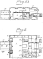
- Fig. 2 shows the terminal connector device 11 inserted in the terminal box 15, with the terminal connector in an inactive position.
- Figs. 3 and 4 show respectively a horizontal section view and a view from above.
- the terminal connector 11 has a rectangular shape and includes on one short side a connection 30 for connection with a supply hose 30' extending from a ramp-mounted liquid source (not shown), a connection 31 for connection of a return line 31', a connection 32 for connection of a compressed air hose 32' extending from the ramp.
- a connection 33 through which current is supplied from a ramp-carried current source (not shown) is also mounted on this short side of the terminal connector 11.
- respective connections 30, 31 and 32 are actively connected with passageways 30'', 31'' and 32'' passing through the terminal connector 11.
- Each of these passageways 30'', 31'' and 32'' open out into an opening in one long side of the terminal connector, and each of said openings have connecting means 30''', 31''' and 32'''.
- the power supply cable 33 is connected to an electric male contact 33' by means of electric conductors (indicated with a broken line). All of the aforesaid components, with the exception of the passageways 30'', 31'' 32'', are also shown in Fig. 4, to which reference is now made. The feature of interest shown in Fig.
- the actuator device 41 resides in an actuator device 41 which is located on the upper side of the terminal connector device 11 and which is pivotal about an axle 40.
- the actuator device has a special configuration and is mounted close to the connection end of the terminal connector device 11 and includes an outwardly projecting, manually operable handle 42.
- the terminal box 15 has a bottom part (not shown), at least three side walls 51, 52 and 53, and a top part (not shown).
- the fourth side may be open, either completely or partially, and is intended to receive the terminal connector device 11, which will be described more fully in the following description of the manner in which the inventive arrangement operates.
- a microswitch 70 (indicated in Fig. 5) which is connected electrically to a box 72 (Fig. 5) which houses a plurality of electrical components.
- the box 72 may be positioned, and is preferably positioned, somewhere outside the terminal box 15.
- connection means 62, 63 and 64 which can be connected to corresponding connection means on the terminal connector device 11, such that the connecting means 30''' on the terminal connector device 11 can be connected sealingly (liquid-tight) to the connecting means 62 on the terminal box 15, and so that the connecting means 31''' can be sealingly connected (liquid-tight) to the connecting means 63 on the terminal box 15, and so that the air supply 32''' can be connected to the connecting means 64 on said terminal box 15.
- the side wall 53 of the terminal box 15 also carries an electrical contact 65 to which the electrical contact part 33' of the terminal connector device 11 is connected.
- the electrical contact 65 is connected by cables (not shown) to an externally accessible electric current supply device 66. All connecting means 62, 63, 64, 66 are connected permanently to corresponding lines in the bus 10.
- the compressed air system of the bus 10 is connected to a compressed air connection 100.
- the wall 51 of the terminal box 15 opposite the wall 53 has mounted thereon a pull-spring loaded, pneumatic double-acting piston/cylinder device 67 which is activated by electric control signals and the piston of which is reciprocatingly movable in the direction of the arrow A.
- the piston/cylinder device is adapted to exert a force on the connected device 11 for movement of the device in one direction (to the right in Fig. 2).
- the piston/cylinder device 67 is acted upon by a pressure spring 68 on both sides of said device.
- Each of the pressure springs 68 (of which the lower is shown in Fig. 2) is mounted on a respective push sleeve.
- the piston-end of the piston/cylinder device is oriented so that it is able to exert a force on one wall of the terminal connector device 11, i.e. the wall opposite the connecting means 30''', 31''', etc.
- the ramp-mounted lines and conductors are connected to the terminal connector device 11.
- the terminal connector device 11 is then inserted into the terminal box 15, wherewith the activator 41 mounted on the terminal connector device 11 activates a microswitch 70 (indicated in Fig. 2A) which then delivers a control signal from the vehicle electrical system to a solenoid valve 71, which is therewith switched to a different state which results in a change in pressure in the piston/cylinder device 67 by virtue of air entering from the air line 100, therewith initiating movement of the piston.
- a notch or like recess on the activator 41 is brought into locking engagement with a pin 75 (Fig. 5).
- the activator 41 therewith prevents the connection with the microswitch 70 being broken unintentionally.
- the piston of the piston/cylinder device 67 is then pressed by the pressure spring 68 against the terminal connector device 11, therewith moving the terminal connector device in a direction towards the wall 53 of the terminal box 15.
- the various connection means 30''', 31''', 32''' and 33' on the terminal connector device 11 are therewith brought into active cooperation with corresponding connecting means on the wall 53 of the terminal box 15.
- connecting means 33 and 33' there will preferably be a given delay in order to avoid unfavourable, and in certain cases dangerous sparking between the male and female electrical contacts.
- an incomplete connection between the male and female contacts may result in the generation of sparks in the worst case, therewith igniting inflammable or explosive vapours, or creating a difficultly released connection between the male and female contacts in the manner of a spot weld.
- the piston of the piston/cylinder device 67 bears against the side of the terminal connector device 11 with a constant force, so as to ensure that the desired contact between the various connecting means of the terminal connector device and the terminal box will be achieved.
- the liquid source and the electric current source on the heating ramp are now connected actively with the internal system of the bus and at least the primary heating of the bus and charging of the battery or batteries thereof can now take place.
- a first function of the arrangement may be to control a basic vehicle temperature, e.g. a basic temperature of 12°C.
- a second function may be to control a high vehicle temperature, for instance a temperature of 18°C.
- a third function may be to control an ignition lock which will prevent the vehicle from being started unintentionally while the vehicle is connected to the ramp-mounted supply facilities.
- a fourth function may include a time relay which controls charging of the vehicle battery or batteries.
- the handle, or thumb grip 42, on the activator 41 is moved so that the microswitch will break the supply of current to the solenoid valve, which is therewith opened and causes the piston of the piston/cylinder device 67 to return to its starting position against the force of the spring 68, whereafter the terminal connector device 11 can be removed from the terminal box 15.
- the pressure springs 68 also have a secondary function. For instance, in the event of malfunctioning of the compressed air supply means, the pressure springs will function to maintain the active engagement of the terminal connector device 11 with the vehicle-mounted system. This prevents the uncontrolled release of liquids and fluids.
- the described and illustrated inventive arrangement enables the different supply sources mounted on the heating ramp to be connected to the internal systems of the vehicle and the coupling device 11 used to this end disconnected from the vehicle internal systems by means of a simple hand manipulation.
- the energy costs entailed by the facilities installed on the vehicle can be optimized by appropriate choice of computer programs, and the electrical terminal box 72 enables these facilities to be remote controlled.
Landscapes
- Physics & Mathematics (AREA)
- Thermal Sciences (AREA)
- Engineering & Computer Science (AREA)
- Mechanical Engineering (AREA)
- Air-Conditioning For Vehicles (AREA)
- Use Of Switch Circuits For Exchanges And Methods Of Control Of Multiplex Exchanges (AREA)
- Small-Scale Networks (AREA)
- Electric Propulsion And Braking For Vehicles (AREA)
- Body Structure For Vehicles (AREA)
- Details Of Connecting Devices For Male And Female Coupling (AREA)
Applications Claiming Priority (3)
| Application Number | Priority Date | Filing Date | Title |
|---|---|---|---|
| SE9401182 | 1994-04-08 | ||
| SE9401182A SE502704C2 (sv) | 1994-04-08 | 1994-04-08 | Anordning vid uppvärmningssystem, för parkerade last- eller personbefordrande fordon, särskilt bussar i linjetrafik |
| EP95916079A EP0701512A1 (de) | 1994-04-08 | 1995-04-06 | Anlage mit mehreren verbindungen |
Related Parent Applications (1)
| Application Number | Title | Priority Date | Filing Date |
|---|---|---|---|
| EP95916079A Division EP0701512A1 (de) | 1994-04-08 | 1995-04-06 | Anlage mit mehreren verbindungen |
Publications (3)
| Publication Number | Publication Date |
|---|---|
| EP0855299A2 true EP0855299A2 (de) | 1998-07-29 |
| EP0855299A3 EP0855299A3 (de) | 1999-02-24 |
| EP0855299B1 EP0855299B1 (de) | 2000-10-18 |
Family
ID=20393577
Family Applications (2)
| Application Number | Title | Priority Date | Filing Date |
|---|---|---|---|
| EP95916079A Withdrawn EP0701512A1 (de) | 1994-04-08 | 1995-04-06 | Anlage mit mehreren verbindungen |
| EP98103939A Expired - Lifetime EP0855299B1 (de) | 1994-04-08 | 1995-04-06 | Anlage mit mehreren Verbindungen |
Family Applications Before (1)
| Application Number | Title | Priority Date | Filing Date |
|---|---|---|---|
| EP95916079A Withdrawn EP0701512A1 (de) | 1994-04-08 | 1995-04-06 | Anlage mit mehreren verbindungen |
Country Status (7)
| Country | Link |
|---|---|
| EP (2) | EP0701512A1 (de) |
| AT (1) | ATE197020T1 (de) |
| DE (1) | DE69519178T2 (de) |
| DK (1) | DK0855299T3 (de) |
| ES (1) | ES2153694T3 (de) |
| SE (1) | SE502704C2 (de) |
| WO (1) | WO1995027630A1 (de) |
Cited By (2)
| Publication number | Priority date | Publication date | Assignee | Title |
|---|---|---|---|---|
| EP1961367A1 (de) * | 2007-02-22 | 2008-08-27 | invendo medical GmbH | Elektrische Steckereinrichtung mit integrierten hydraulischen/pneumatischen Anschlüssen |
| EP1989073A4 (de) * | 2006-02-27 | 2010-03-10 | Jp Ei & Vvs Teknik Ab | Andockeinheit zum heizen/kühlen eines geparkten fahrzeugs sowie zur verbindung mit solch einer andockeinheit angeordnetes fahrzeug |
Family Cites Families (4)
| Publication number | Priority date | Publication date | Assignee | Title |
|---|---|---|---|---|
| SE440734B (sv) * | 1981-11-25 | 1985-08-19 | El & Dieselservice Ab | Anordning vid fordon, speciellt bussar, for konstanthallning av vetskemengden i fordonets vetskeburna uppvermningssystem |
| US4624472A (en) * | 1984-01-18 | 1986-11-25 | Stuart Clifton F | Coupling mechanism for coupling fluid and electrical lines between adjacent vehicles |
| JP2912631B2 (ja) * | 1989-05-17 | 1999-06-28 | 津田駒工業株式会社 | 自動着脱コネクタ装置 |
| US5462439A (en) * | 1993-04-19 | 1995-10-31 | Keith; Arlie L. | Charging batteries of electric vehicles |
-
1994
- 1994-04-08 SE SE9401182A patent/SE502704C2/sv not_active IP Right Cessation
-
1995
- 1995-04-06 ES ES98103939T patent/ES2153694T3/es not_active Expired - Lifetime
- 1995-04-06 WO PCT/SE1995/000369 patent/WO1995027630A1/en not_active Ceased
- 1995-04-06 DK DK98103939T patent/DK0855299T3/da active
- 1995-04-06 AT AT98103939T patent/ATE197020T1/de not_active IP Right Cessation
- 1995-04-06 EP EP95916079A patent/EP0701512A1/de not_active Withdrawn
- 1995-04-06 DE DE69519178T patent/DE69519178T2/de not_active Expired - Fee Related
- 1995-04-06 EP EP98103939A patent/EP0855299B1/de not_active Expired - Lifetime
Non-Patent Citations (1)
| Title |
|---|
| None |
Cited By (3)
| Publication number | Priority date | Publication date | Assignee | Title |
|---|---|---|---|---|
| EP1989073A4 (de) * | 2006-02-27 | 2010-03-10 | Jp Ei & Vvs Teknik Ab | Andockeinheit zum heizen/kühlen eines geparkten fahrzeugs sowie zur verbindung mit solch einer andockeinheit angeordnetes fahrzeug |
| EP1961367A1 (de) * | 2007-02-22 | 2008-08-27 | invendo medical GmbH | Elektrische Steckereinrichtung mit integrierten hydraulischen/pneumatischen Anschlüssen |
| US7621766B2 (en) | 2007-02-22 | 2009-11-24 | Invendo Medical Gmbh | Electric plug device including integrated hydraulic/pneumatic ports |
Also Published As
| Publication number | Publication date |
|---|---|
| SE9401182L (sv) | 1995-10-09 |
| DE69519178T2 (de) | 2001-05-31 |
| ATE197020T1 (de) | 2000-11-15 |
| SE9401182D0 (sv) | 1994-04-08 |
| SE502704C2 (sv) | 1995-12-11 |
| EP0855299A3 (de) | 1999-02-24 |
| EP0855299B1 (de) | 2000-10-18 |
| DE69519178D1 (de) | 2000-11-23 |
| DK0855299T3 (da) | 2001-02-05 |
| ES2153694T3 (es) | 2001-03-01 |
| WO1995027630A1 (en) | 1995-10-19 |
| EP0701512A1 (de) | 1996-03-20 |
Similar Documents
| Publication | Publication Date | Title |
|---|---|---|
| US11203262B2 (en) | Transport climate control system with an accessory power distribution unit for managing transport climate control loads | |
| US9114716B2 (en) | Method and apparatus for high-voltage DC charging of battery-electric and plug-in hybrid electric vehicles | |
| US4414462A (en) | Tank car heating system | |
| US3497027A (en) | Electric automobile | |
| CN100577496C (zh) | 用于传输电能、气动能或水力能的方法以及能量传输系统 | |
| US20200044464A1 (en) | Fast rechargeable battery assembly and recharging equipment | |
| US11839782B2 (en) | Safety method and control device for an emergency vehicle | |
| EP1548901B1 (de) | Anschlusseinrichtung einer externen Energiequelle für ein elektrisches Fahrzeug | |
| US6817879B2 (en) | Service port configurations | |
| JPH04334906A (ja) | 補助電源を備えた電気自動車 | |
| EP0855299B1 (de) | Anlage mit mehreren Verbindungen | |
| SE542943C2 (en) | A charging device for a functional module and a vehicle assembled from a set of modules | |
| EP3790154B1 (de) | Optimiertes netzkabel zur leistungsübertragung an ein transportklimaregelungssystem | |
| DE102020211783A1 (de) | Anhänger mit einem Stromerzeuger | |
| US20240351685A1 (en) | Interface system for connecting trolleys | |
| CN111775679B (zh) | 操纵驱动系统以及具有该操纵驱动系统的车辆和套件 | |
| US11370315B2 (en) | Hands-free charging system with internal power source | |
| CN223764739U (zh) | 停机装置、停机设备及车辆 | |
| CN114156103A (zh) | 维修开关、维修开关的控制方法和电动汽车 |
Legal Events
| Date | Code | Title | Description |
|---|---|---|---|
| PUAI | Public reference made under article 153(3) epc to a published international application that has entered the european phase |
Free format text: ORIGINAL CODE: 0009012 |
|
| 17P | Request for examination filed |
Effective date: 19980316 |
|
| AC | Divisional application: reference to earlier application |
Ref document number: 701512 Country of ref document: EP |
|
| AK | Designated contracting states |
Kind code of ref document: A2 Designated state(s): AT BE CH DE DK ES FR GB IE IT LI NL PT |
|
| PUAL | Search report despatched |
Free format text: ORIGINAL CODE: 0009013 |
|
| AK | Designated contracting states |
Kind code of ref document: A3 Designated state(s): AT BE CH DE DK ES FR GB IE IT LI NL PT |
|
| GRAG | Despatch of communication of intention to grant |
Free format text: ORIGINAL CODE: EPIDOS AGRA |
|
| 17Q | First examination report despatched |
Effective date: 19991213 |
|
| GRAG | Despatch of communication of intention to grant |
Free format text: ORIGINAL CODE: EPIDOS AGRA |
|
| GRAH | Despatch of communication of intention to grant a patent |
Free format text: ORIGINAL CODE: EPIDOS IGRA |
|
| GRAH | Despatch of communication of intention to grant a patent |
Free format text: ORIGINAL CODE: EPIDOS IGRA |
|
| GRAA | (expected) grant |
Free format text: ORIGINAL CODE: 0009210 |
|
| AC | Divisional application: reference to earlier application |
Ref document number: 701512 Country of ref document: EP |
|
| AK | Designated contracting states |
Kind code of ref document: B1 Designated state(s): AT BE CH DE DK ES FR GB IE IT LI NL PT |
|
| REF | Corresponds to: |
Ref document number: 197020 Country of ref document: AT Date of ref document: 20001115 Kind code of ref document: T |
|
| REG | Reference to a national code |
Ref country code: CH Ref legal event code: EP |
|
| REG | Reference to a national code |
Ref country code: IE Ref legal event code: FG4D |
|
| REF | Corresponds to: |
Ref document number: 69519178 Country of ref document: DE Date of ref document: 20001123 |
|
| ET | Fr: translation filed | ||
| ITF | It: translation for a ep patent filed | ||
| PG25 | Lapsed in a contracting state [announced via postgrant information from national office to epo] |
Ref country code: PT Free format text: LAPSE BECAUSE OF FAILURE TO SUBMIT A TRANSLATION OF THE DESCRIPTION OR TO PAY THE FEE WITHIN THE PRESCRIBED TIME-LIMIT Effective date: 20010118 |
|
| REG | Reference to a national code |
Ref country code: CH Ref legal event code: NV Representative=s name: BUGNION S.A. |
|
| REG | Reference to a national code |
Ref country code: DK Ref legal event code: T3 |
|
| REG | Reference to a national code |
Ref country code: ES Ref legal event code: FG2A Ref document number: 2153694 Country of ref document: ES Kind code of ref document: T3 |
|
| PG25 | Lapsed in a contracting state [announced via postgrant information from national office to epo] |
Ref country code: IE Free format text: LAPSE BECAUSE OF NON-PAYMENT OF DUE FEES Effective date: 20010406 |
|
| PLBE | No opposition filed within time limit |
Free format text: ORIGINAL CODE: 0009261 |
|
| STAA | Information on the status of an ep patent application or granted ep patent |
Free format text: STATUS: NO OPPOSITION FILED WITHIN TIME LIMIT |
|
| 26N | No opposition filed | ||
| REG | Reference to a national code |
Ref country code: GB Ref legal event code: IF02 |
|
| REG | Reference to a national code |
Ref country code: IE Ref legal event code: MM4A |
|
| PGFP | Annual fee paid to national office [announced via postgrant information from national office to epo] |
Ref country code: GB Payment date: 20040325 Year of fee payment: 10 |
|
| PGFP | Annual fee paid to national office [announced via postgrant information from national office to epo] |
Ref country code: FR Payment date: 20040330 Year of fee payment: 10 |
|
| PGFP | Annual fee paid to national office [announced via postgrant information from national office to epo] |
Ref country code: NL Payment date: 20040415 Year of fee payment: 10 |
|
| PGFP | Annual fee paid to national office [announced via postgrant information from national office to epo] |
Ref country code: BE Payment date: 20040422 Year of fee payment: 10 |
|
| PGFP | Annual fee paid to national office [announced via postgrant information from national office to epo] |
Ref country code: DK Payment date: 20040426 Year of fee payment: 10 |
|
| PG25 | Lapsed in a contracting state [announced via postgrant information from national office to epo] |
Ref country code: IT Free format text: LAPSE BECAUSE OF NON-PAYMENT OF DUE FEES Effective date: 20050406 Ref country code: GB Free format text: LAPSE BECAUSE OF NON-PAYMENT OF DUE FEES Effective date: 20050406 |
|
| PGFP | Annual fee paid to national office [announced via postgrant information from national office to epo] |
Ref country code: CH Payment date: 20050414 Year of fee payment: 11 |
|
| PGFP | Annual fee paid to national office [announced via postgrant information from national office to epo] |
Ref country code: ES Payment date: 20050422 Year of fee payment: 11 |
|
| PGFP | Annual fee paid to national office [announced via postgrant information from national office to epo] |
Ref country code: AT Payment date: 20050426 Year of fee payment: 11 |
|
| PGFP | Annual fee paid to national office [announced via postgrant information from national office to epo] |
Ref country code: DE Payment date: 20050427 Year of fee payment: 11 |
|
| PG25 | Lapsed in a contracting state [announced via postgrant information from national office to epo] |
Ref country code: BE Free format text: LAPSE BECAUSE OF NON-PAYMENT OF DUE FEES Effective date: 20050430 |
|
| PG25 | Lapsed in a contracting state [announced via postgrant information from national office to epo] |
Ref country code: DK Free format text: LAPSE BECAUSE OF NON-PAYMENT OF DUE FEES Effective date: 20050502 |
|
| BERE | Be: lapsed |
Owner name: *UWE-VERKEN A.B. Effective date: 20050430 |
|
| PG25 | Lapsed in a contracting state [announced via postgrant information from national office to epo] |
Ref country code: NL Free format text: LAPSE BECAUSE OF NON-PAYMENT OF DUE FEES Effective date: 20051101 |
|
| REG | Reference to a national code |
Ref country code: DK Ref legal event code: EBP |
|
| GBPC | Gb: european patent ceased through non-payment of renewal fee |
Effective date: 20050406 |
|
| PG25 | Lapsed in a contracting state [announced via postgrant information from national office to epo] |
Ref country code: FR Free format text: LAPSE BECAUSE OF NON-PAYMENT OF DUE FEES Effective date: 20051230 |
|
| NLV4 | Nl: lapsed or anulled due to non-payment of the annual fee |
Effective date: 20051101 |
|
| REG | Reference to a national code |
Ref country code: FR Ref legal event code: ST Effective date: 20051230 |
|
| PG25 | Lapsed in a contracting state [announced via postgrant information from national office to epo] |
Ref country code: AT Free format text: LAPSE BECAUSE OF NON-PAYMENT OF DUE FEES Effective date: 20060406 |
|
| PG25 | Lapsed in a contracting state [announced via postgrant information from national office to epo] |
Ref country code: ES Free format text: LAPSE BECAUSE OF NON-PAYMENT OF DUE FEES Effective date: 20060407 |
|
| PG25 | Lapsed in a contracting state [announced via postgrant information from national office to epo] |
Ref country code: LI Free format text: LAPSE BECAUSE OF NON-PAYMENT OF DUE FEES Effective date: 20060430 Ref country code: CH Free format text: LAPSE BECAUSE OF NON-PAYMENT OF DUE FEES Effective date: 20060430 |
|
| PG25 | Lapsed in a contracting state [announced via postgrant information from national office to epo] |
Ref country code: DE Free format text: LAPSE BECAUSE OF NON-PAYMENT OF DUE FEES Effective date: 20061101 |
|
| REG | Reference to a national code |
Ref country code: CH Ref legal event code: PL |
|
| REG | Reference to a national code |
Ref country code: ES Ref legal event code: FD2A Effective date: 20060407 |
|
| BERE | Be: lapsed |
Owner name: *UWE-VERKEN A.B. Effective date: 20050430 |