EP0855211B1 - Membrantrennvorrichtung - Google Patents
Membrantrennvorrichtung Download PDFInfo
- Publication number
- EP0855211B1 EP0855211B1 EP97117737A EP97117737A EP0855211B1 EP 0855211 B1 EP0855211 B1 EP 0855211B1 EP 97117737 A EP97117737 A EP 97117737A EP 97117737 A EP97117737 A EP 97117737A EP 0855211 B1 EP0855211 B1 EP 0855211B1
- Authority
- EP
- European Patent Office
- Prior art keywords
- membrane
- cylindrical
- annular space
- membrane separation
- separation methods
- Prior art date
- Legal status (The legal status is an assumption and is not a legal conclusion. Google has not performed a legal analysis and makes no representation as to the accuracy of the status listed.)
- Expired - Lifetime
Links
- 239000012528 membrane Substances 0.000 title claims abstract description 93
- 238000000926 separation method Methods 0.000 title claims abstract description 33
- 239000012466 permeate Substances 0.000 claims abstract description 7
- 239000012141 concentrate Substances 0.000 claims abstract description 6
- 239000000126 substance Substances 0.000 claims description 10
- 125000006850 spacer group Chemical group 0.000 claims description 8
- 230000008878 coupling Effects 0.000 claims description 2
- 238000010168 coupling process Methods 0.000 claims description 2
- 238000005859 coupling reaction Methods 0.000 claims description 2
- 238000005070 sampling Methods 0.000 claims 1
- 238000000605 extraction Methods 0.000 abstract 1
- FAPWRFPIFSIZLT-UHFFFAOYSA-M Sodium chloride Chemical compound [Na+].[Cl-] FAPWRFPIFSIZLT-UHFFFAOYSA-M 0.000 description 7
- 239000007788 liquid Substances 0.000 description 7
- 239000002351 wastewater Substances 0.000 description 6
- XLYOFNOQVPJJNP-UHFFFAOYSA-N water Substances O XLYOFNOQVPJJNP-UHFFFAOYSA-N 0.000 description 5
- IJGRMHOSHXDMSA-UHFFFAOYSA-N Atomic nitrogen Chemical compound N#N IJGRMHOSHXDMSA-UHFFFAOYSA-N 0.000 description 4
- 238000000034 method Methods 0.000 description 4
- 239000011780 sodium chloride Substances 0.000 description 4
- 238000000108 ultra-filtration Methods 0.000 description 4
- 238000001914 filtration Methods 0.000 description 3
- 238000011835 investigation Methods 0.000 description 3
- ISPYQTSUDJAMAB-UHFFFAOYSA-N 2-chlorophenol Chemical compound OC1=CC=CC=C1Cl ISPYQTSUDJAMAB-UHFFFAOYSA-N 0.000 description 2
- 239000007864 aqueous solution Substances 0.000 description 2
- 238000011026 diafiltration Methods 0.000 description 2
- 239000012530 fluid Substances 0.000 description 2
- 239000007789 gas Substances 0.000 description 2
- 239000000463 material Substances 0.000 description 2
- 229910052751 metal Inorganic materials 0.000 description 2
- 239000002184 metal Substances 0.000 description 2
- 238000001471 micro-filtration Methods 0.000 description 2
- 238000001728 nano-filtration Methods 0.000 description 2
- 229910052757 nitrogen Inorganic materials 0.000 description 2
- 230000000149 penetrating effect Effects 0.000 description 2
- 239000002985 plastic film Substances 0.000 description 2
- 229920006255 plastic film Polymers 0.000 description 2
- 238000004064 recycling Methods 0.000 description 2
- 238000001223 reverse osmosis Methods 0.000 description 2
- 238000004088 simulation Methods 0.000 description 2
- 238000010792 warming Methods 0.000 description 2
- 238000005406 washing Methods 0.000 description 2
- GSMITOPOWVFGOM-UHFFFAOYSA-N 1-(tert-butylamino)-3-(2,5-dichlorophenoxy)propan-2-ol;hydron;chloride Chemical compound Cl.CC(C)(C)NCC(O)COC1=CC(Cl)=CC=C1Cl GSMITOPOWVFGOM-UHFFFAOYSA-N 0.000 description 1
- RZWHKKIXMPLQEM-UHFFFAOYSA-N 1-chloropropan-1-ol Chemical compound CCC(O)Cl RZWHKKIXMPLQEM-UHFFFAOYSA-N 0.000 description 1
- 239000002033 PVDF binder Substances 0.000 description 1
- 239000003463 adsorbent Substances 0.000 description 1
- 230000002411 adverse Effects 0.000 description 1
- 230000001476 alcoholic effect Effects 0.000 description 1
- 230000001580 bacterial effect Effects 0.000 description 1
- 238000010923 batch production Methods 0.000 description 1
- 239000000149 chemical water pollutant Substances 0.000 description 1
- 239000012459 cleaning agent Substances 0.000 description 1
- 239000000356 contaminant Substances 0.000 description 1
- 238000011109 contamination Methods 0.000 description 1
- 238000001816 cooling Methods 0.000 description 1
- 238000009295 crossflow filtration Methods 0.000 description 1
- 239000000839 emulsion Substances 0.000 description 1
- 238000005516 engineering process Methods 0.000 description 1
- 230000007613 environmental effect Effects 0.000 description 1
- 239000004744 fabric Substances 0.000 description 1
- 239000000835 fiber Substances 0.000 description 1
- 239000000706 filtrate Substances 0.000 description 1
- 238000005194 fractionation Methods 0.000 description 1
- 239000003673 groundwater Substances 0.000 description 1
- 239000000383 hazardous chemical Substances 0.000 description 1
- 229910001385 heavy metal Inorganic materials 0.000 description 1
- 239000010842 industrial wastewater Substances 0.000 description 1
- 239000011261 inert gas Substances 0.000 description 1
- 230000014759 maintenance of location Effects 0.000 description 1
- 239000011859 microparticle Substances 0.000 description 1
- 239000000203 mixture Substances 0.000 description 1
- 239000002245 particle Substances 0.000 description 1
- 239000004033 plastic Substances 0.000 description 1
- 229920002981 polyvinylidene fluoride Polymers 0.000 description 1
- 238000011085 pressure filtration Methods 0.000 description 1
- 230000008929 regeneration Effects 0.000 description 1
- 238000011069 regeneration method Methods 0.000 description 1
- 239000012465 retentate Substances 0.000 description 1
- 150000003839 salts Chemical class 0.000 description 1
- 239000002689 soil Substances 0.000 description 1
- 239000007787 solid Substances 0.000 description 1
- 239000000243 solution Substances 0.000 description 1
- 239000002352 surface water Substances 0.000 description 1
- 239000000725 suspension Substances 0.000 description 1
- 238000005496 tempering Methods 0.000 description 1
- 231100000331 toxic Toxicity 0.000 description 1
- 230000002588 toxic effect Effects 0.000 description 1
- 238000009423 ventilation Methods 0.000 description 1
- 239000002699 waste material Substances 0.000 description 1
- 239000003643 water by type Substances 0.000 description 1
Images

Classifications
-
- B—PERFORMING OPERATIONS; TRANSPORTING
- B01—PHYSICAL OR CHEMICAL PROCESSES OR APPARATUS IN GENERAL
- B01D—SEPARATION
- B01D65/00—Accessories or auxiliary operations, in general, for separation processes or apparatus using semi-permeable membranes
- B01D65/08—Prevention of membrane fouling or of concentration polarisation
-
- B—PERFORMING OPERATIONS; TRANSPORTING
- B01—PHYSICAL OR CHEMICAL PROCESSES OR APPARATUS IN GENERAL
- B01D—SEPARATION
- B01D61/00—Processes of separation using semi-permeable membranes, e.g. dialysis, osmosis or ultrafiltration; Apparatus, accessories or auxiliary operations specially adapted therefor
- B01D61/14—Ultrafiltration; Microfiltration
- B01D61/18—Apparatus therefor
-
- B—PERFORMING OPERATIONS; TRANSPORTING
- B01—PHYSICAL OR CHEMICAL PROCESSES OR APPARATUS IN GENERAL
- B01D—SEPARATION
- B01D63/00—Apparatus in general for separation processes using semi-permeable membranes
- B01D63/06—Tubular membrane modules
- B01D63/062—Tubular membrane modules with membranes on a surface of a support tube
- B01D63/065—Tubular membrane modules with membranes on a surface of a support tube on the outer surface thereof
-
- B—PERFORMING OPERATIONS; TRANSPORTING
- B01—PHYSICAL OR CHEMICAL PROCESSES OR APPARATUS IN GENERAL
- B01D—SEPARATION
- B01D2321/00—Details relating to membrane cleaning, regeneration, sterilization or to the prevention of fouling
- B01D2321/18—Use of gases
- B01D2321/185—Aeration
-
- B—PERFORMING OPERATIONS; TRANSPORTING
- B01—PHYSICAL OR CHEMICAL PROCESSES OR APPARATUS IN GENERAL
- B01D—SEPARATION
- B01D2321/00—Details relating to membrane cleaning, regeneration, sterilization or to the prevention of fouling
- B01D2321/20—By influencing the flow
- B01D2321/2008—By influencing the flow statically
- B01D2321/2016—Static mixers; Turbulence generators
-
- G—PHYSICS
- G01—MEASURING; TESTING
- G01N—INVESTIGATING OR ANALYSING MATERIALS BY DETERMINING THEIR CHEMICAL OR PHYSICAL PROPERTIES
- G01N1/00—Sampling; Preparing specimens for investigation
- G01N1/28—Preparing specimens for investigation including physical details of (bio-)chemical methods covered elsewhere, e.g. G01N33/50, C12Q
- G01N1/40—Concentrating samples
-
- G—PHYSICS
- G01—MEASURING; TESTING
- G01N—INVESTIGATING OR ANALYSING MATERIALS BY DETERMINING THEIR CHEMICAL OR PHYSICAL PROPERTIES
- G01N33/00—Investigating or analysing materials by specific methods not covered by groups G01N1/00 - G01N31/00
- G01N33/18—Water
Definitions
- the invention relates to a test device for Membrane separation process according to the preamble of the claim 1.
- test devices for membrane separation processes use flat membranes with circular or square shapes Crops in a two-dimensional plane be used.
- These known devices have Test cells for cross-flow and pressure filtration and generally for membrane engineering investigations be available. They consist of a two-part Pressure housing, being between the upper and lower housing part one supported by a filter support Membrane is stored flat to the one this membrane is open to flow channel, the ends of which have an inlet connection and a concentrate outlet connection connected is.
- the filtrate is connected to the membrane by a Flow channel derived.
- Flow channel derived.
- baffles are between Inlet connection and membrane attached. The one the flow channel adjacent to the membrane directs the fluid in a parallel spiral or meandering path the membrane.
- the membrane surfaces can be not sufficient for material separation use. About up to 35% of the membrane surface remain unused. This not optimal membrane utilization adversely affects the throughput of the Test cell off. Therefore, it is very hesitant Concentration. It means wasting time and without Vacuum circulation unnecessarily warming up the Test medium and possibly additional cooling or tempering.
- the medium is to be regarded as a hazardous substance.
- the toxic medium to be examined is located originally abroad: transport at the border crossing problematic.
- From US 4702842 A is a membrane separation device known for reverse osmosis and ultrafiltration with a pressure vessel to hold membrane elements, which flows through a liquid to be cleaned be, and with a surrounding the membrane elements Circulation channel for the liquid.
- DE 2420728 A relates to a membrane separation device for separating solids from liquids with a container in which semipermeable membrane units are arranged in parallel. This is supposed to the total membrane surface are enlarged at while reducing the size of the container.
- EP 0448466 A discloses a membrane separation device for ultra or microfiltration of liquids with membranes made from a tubular Bundles of fibers exist, which with recirculation are flowed through and arranged in a container are.
- EP 0605826 A is a filtration device for separating fine adsorbent particles known from liquids with a variety of membranes, the vertical and parallel in a container are spaced from each other.
- a pump sucks process liquid through the filtration unit. Gas bubbles become in the spaces between the membranes blown in by means of a blower.
- the object of the present invention is therefore in it a test facility for membrane separation processes to develop the relatively light, portable and is mobile and the quick and reliable examinations environmentally relevant fabrics.
- the test device according to the invention for membrane separation processes is a compact and handy test device producible that does not require a booster pump.
- the overflow of the membrane is covered by a Pressure working circulation pump ensures which is designed so that it also contains liquids pumps higher salt contents (up to 15% by weight).
- the invention Test facility for membrane separation processes can with relatively small test volumes, for example of 100 ml, working, resulting in a quick concentration and thus a short test time can be achieved.
- the dead volume of the device can be kept very small are - less than 1% - because all rooms and channels be flowed through. Warming up the subject to be examined Substance is negligible because of the pressure differences circulation is very low - up to a maximum 0.5 bar - because the working pressure is caused by an external Pressure source (e.g. gas bottle) set becomes.
- an external Pressure source e.g. gas bottle
- test device for membrane separation processes enables a direct environmental Use for field trials. This makes rapid analytics for membrane separability of contaminants aqueous solutions significantly improved.
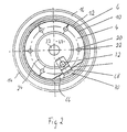
- the drawing shows a test device for membrane separation processes 2 with a cylindrical membrane holder 4 - preferably made of plastic - on the a membrane 6 is arranged cylindrically - that is, three-dimensionally around which there is a cylindrical spiral 8 - preferably from a plastic film - by means of a cylindrical spacer 10 spaced apart is, the spacer 10 by the spiral 8 is clamped onto the membrane 6.
- the spacer 10 is a turbulence device in between the membrane 6 and the spiral 8 formed inner cylindrical annulus 12 formed.
- the cylindrical spiral 8 is of an outer cylinder 14 - preferably made of metal - surrounded by a distance, so that between the cylinder 14 and the spiral 8th an outer cylindrical annulus 16 is formed.
- the cylindrical membrane holder 4 is with the Cylinder jacket 18 penetrating in the axial direction To provide manifold holes 20, which cross holes 22 in the cylinder jacket and over the membrane 6 with the Annulus 6 are connected.
- a cylindrical support body 24 - On the inside of the cylinder of the membrane holder 4 is a cylindrical support body 24 - preferably made of Metal - arranged.
- the cylindrical arrangement of cylindrical Support body 24, membrane holder 4, spacer 10, Spiral 8 and cylinder 14 is between a cover plate 26 and a bottom plate 28, the outer Cylinder 14 and the cylindrical membrane holder 4 by means of O-rings 30, 32 in the top and bottom plates are arranged sealed. The top and bottom plate are clamped together by a central bolt 33.
- a pump housing 34 is located under the base plate 28 flanged, in which a rotor 36 in a rotor space 38 and a pump impeller 40 in an impeller space 42 of a circulation pump 44, the rotor 36 preferably via a permanent magnet coupling 46 is driven by an electric motor (not shown).
- the of the cylindrical membrane holder 4 or the cylindrical support body 24 enclosed interior 47 stands over at least one in the base plate 28 trained bore 48 on the suction side with the impeller chamber 42 in connection, which in turn on the pressure side peripherally via bores 50 with the outer annular space 16 and through bores 52 with the inner annulus 12 in Connection is established.
- the outer annular space 16 is over bores 53, an annular channel 55 and formed in the cover plate at least one circulation channel 54, which in the Cover plate is formed with the interior 47 in Connection.
- the flow velocity in the outside Annulus 16 is adjustable with the aid of an adjusting screw 56, with which the flow cross section of the bore 53 is adjustable.
- the inner annulus 12 with the spacer 10 stands over bores 57 with the annular channel 55 in connection.
- An inlet connection 58 leads over the cover plate 26 into the interior 47. Controlled by valves (not shown) flows continuously through the inlet port 58 or discontinuously the medium to be examined, for example contaminated water. The medium will via the inlet connection 58 further with air or nitrogen pressurized.
- an outlet port 60 for continuous permeate removal and vacuum connection connected.
- the outer annular space 16 is via a ventilation device 62 bleedable.
- test facility for membrane separation processes.
- a contaminated (aqueous) substance to be examined is via the inlet connection 58 into the interior 47 given and over the same nozzle with Working pressure - for example 3 to 60 bar, to achieve high yield up to 240 bar - using compressed air or inert gas pressure (nitrogen pressure).
- the substance passes through the holes 48 in the circulation pump 44 and is over the holes 50 and 52 in the outer annulus 16 and the inner Annulus 12 promoted where the substance back into the Interior space 47 through holes 53 and 57 and the circulation channel 54 arrives.
- the spiral 8 is pressed against the cylindrical spacer 10 pressed, which thereby the membrane 6th presses against the cylindrical membrane holder 4.
- the plastic film used for the spiral can be a Have a thickness of 0.2 to 2 mm and for example consist of PVDF or PVA.
- the flow cross sections are selected or adjustable so that the flow rate - 0.0 to 0.09 m / sec. - in the outside Annulus 16 is smaller than the flow rate - 0.5 to 5 m / sec. - Is in the inner annulus 12. Due to the working pressure, at least part of the permeate pressed through the membrane and passes through the Cross bores 22 in the collecting bores 20, from which it over the outlet port 60 continuously or discontinuously is removable.
- the concentrated substance is recirculated and can be removed via the concentrate dispensing nozzle 64 can be removed. Over the inlet nozzle 58 becomes the same amount of substance as the amount of permeate removed.
Landscapes
- Chemical & Material Sciences (AREA)
- Chemical Kinetics & Catalysis (AREA)
- Engineering & Computer Science (AREA)
- Water Supply & Treatment (AREA)
- Separation Using Semi-Permeable Membranes (AREA)
- Control And Other Processes For Unpacking Of Materials (AREA)
- Chair Legs, Seat Parts, And Backrests (AREA)
Description
- Mikrofiltration (Trennung von Mikro-Teilchen bei Suspensionen),
- Ultrafiltration (Separieren von molekularen Anteilen oder von Emulsionen),
- Diafiltration (Rückhaltung von Molekülen und Abführung von salzhaltigen oder alkoholischen Phasen aus wässrigen Lösungen),
- Nanofiltration (molekulare und ionale Fraktionierung),
- Umkehrosmose (Abführung von organischen Lösungen und Aufkonzentrierung von salzhaltigen Gewässern).
- Petrochemisches Prozeßwasser: 5 % Chlorpropanol und 1,8 % HCl,
- Technologisches Abwasser aus der chemischen Industrie: 2,4 % Chlorphenol, 5 % NaCl,
- Abwasser aus Bodenwäsche einiger militärischer Objekte: Öl, Reinigungsmittel, Reststoff-Simulation nach ABC-Waffeneinsatz,
- Abwasser aus Ionentauscher-Regenerierungsprozessen: Überwiegend NaCl-Salze mit erhöhter Konzentration,
- Aufbereitung vom Wäschereiabwasser,
- galvanisches Abwasser, Spülbad-Recycling: Schwermetalle und H2O.
- Fig. 1
- einen senkrechten Schnitt durch eine erfindungsgemäße Testeinrichtung für Membrantrennverfahren und
- Fig. 2
- einen Horizontalschnitt A-A durch die Testeinrichtung für Membrantrennverfahren nach Fig. 1.
Claims (11)
- Testeinrichtung für Membrantrennverfahren, mit einer zylindrischen Membran (6), die abgedichtet zwischen einer Deckplatte (26) und einer Bodenplatte (28) angeordnet ist und die beabstandet von einem abgedichtet in der Deckplatte und der Bodenplatte angeordneten zylindrischen Bauteil (14; 8) umgeben ist zur Bildung eines zylindrischen Ringraumes (16),
gekennzeichnet durch folgende Merkmale:a) Eine zylindrische Membranhalterung (4) ist abgedichtet zwischen der Deckplatte (26) und der Bodenplatte (28) angeordnet,b) die Membran (6) ist auf der zylindrischen Außenfläche der Membranhalterung (4) angeordnet,c) in der Membranhalterung (4) sind mit der Membran (6) in Verbindung stehende Sammelräume (20) für Permeat ausgebildet, an die ein Permeatauslass (60) angeschlossen ist,d) die Sammelräume (20) sind durch axiale im Mantel der Membranhalterung (4) angeordnete miteinander in Verbindung stehende Bohrungen gebildet,e) die Bohrungen bzw. Sammelräume (20) stehen über offene in der Außenfläche der Membranhalterung mündende Bohrungen (22) mit der Membran (6) in Verbindung,f) eine Zirkulationspumpe (44) steht saugseitig mit einem von der zylindrischen Membranhalterung (4) und der Deck- und Bodenplatte eingeschlossenen Innenraum (47) und druckseitig mit dem zwischen Membranhalterung (4) und dem zylindrischen Bauteil (14; 8) gebildeten Ringraum (16) in Verbindung,g) die Saugseite der Zirkulationspumpe (44) steht über in der Bodenplatte (28) ausgebildete Bohrungen (48) mit dem Innenraum (47) in Verbindung,h) die Druckseite der Zirkulationspumpe (4) steht über in der Bodenplatte (28) ausgebildete Bohrungen (50) mit dem äußeren Ringraum (16) in Verbindung,i) der Ringraum (16) ist über einen in der Deckplatte (26) ausgebildeten Zirkulationskanal (54) mit dem Innenraum (47) verbunden,j) in den Innenraum (47) ist über einen Einlass (58) eine zu untersuchende und mit Druck beaufschlagbare Substanz einspeisbar,k) die Zirkulationspumpe (44) weist druckseitig einen Auslass (64) zur Entnahme von Konzentrat auf. - Testeinrichtung für Membrantrennverfahren nach Anspruch 1, dadurch gekennzeichnet, dass die Membran (6) von einem zylindrischen Abstandshalter (10) umgeben ist, welcher von einer zylindrischen Spirale (8) in radialer Richtung belastet ist und die Membran (6) beaufschlagt, wobei zwischen der zylindrischen Spirale (8) und der Membranhalterung (4) bzw. der Membran (6) ein innerer Ringraum (12) gebildet wird, welcher mit der Druckseite der Zirkulationspumpe verbunden ist und mit dem Zirkulationskanal (54) in Verbindung steht.
- Testeinrichtung für Membrantrennverfahren nach Anspruch 1 oder 2, dadurch gekennzeichnet, dass die Druckseite der Zirkulationspumpe (4) über in der Bodenplatte (28) ausgebildete Bohrungen (52) mit dem inneren Ringraum (12) in Verbindung steht.
- Testeinrichtung für Membrantrennverfahren nach Anspruch 2, dadurch gekennzeichnet, dass der Abstandshalter (10) als Turbulenzeinrichtung für die den inneren Ringraum (12) durchströmende Substanz ausgebildet ist.
- Testeinrichtung für Membrantrennverfahren nach Anspruch 1 oder 2, dadurch gekennzeichnet, dass in der Deckplatte (26) ein Ringkanal (55) ausgebildet ist, der über den Zirkulationskanal (54) mit dem Innenraum (47) und über Bohrungen (53, 57) in der Deckplatte mit dem äußeren Ringraum (16) und dem inneren Ringraum (12) verbunden ist.
- Testeinrichtung für Membrantrennverfahren nach Anspruch 1 oder 3, dadurch gekennzeichnet, dass die Zirkulationspumpe (44) von einem Elektromotor über eine Permanent-Magnetkupplung (46) angetrieben ist.
- Testeinrichtung für Membrantrennverfahren nach Anspruch 5, dadurch gekennzeichnet, dass die Strömungsgeschwindigkeit im äußeren Ringraum (16) mittels einer in der Wandung der Bohrung (53) angeordneten Justiereinrichtung (56) einstellbar ist.
- Testeinrichtung für Membrantrennverfahren nach Anspruch 7, dadurch gekennzeichnet, dass die Strömungsgeschwindigkeit im äußeren Ringraum (16) niedriger eingestellt ist als im inneren Ringraum (12).
- Testeinrichtung für Membrantrennverfahren nach Anspruch 1 oder 2, dadurch gekennzeichnet, dass die zylindrische Membranhalterung (4) innenseitig einen zylindrischen Stützkörper (24) aufweist.
- Testeinrichtung für Membrantrennverfahren nach einem der vorhergehenden Ansprüche, dadurch gekennzeichnet, dass die Deckplatte (26) und die Bodenplatte (28) mit Hilfe eines Schraubbolzens (33) miteinander verbunden sind.
- Testeinrichtung für Membrantrennverfahren nach einem. der vorhergehenden Ansprüche, dadurch gekennzeichnet, dass der äußere Ringraum (16) entlüftbar (62) ausgebildet ist.
Applications Claiming Priority (2)
| Application Number | Priority Date | Filing Date | Title |
|---|---|---|---|
| DE19702902A DE19702902C1 (de) | 1997-01-28 | 1997-01-28 | Membrantrennvorrichtung |
| DE19702902 | 1997-01-28 |
Publications (2)
| Publication Number | Publication Date |
|---|---|
| EP0855211A1 EP0855211A1 (de) | 1998-07-29 |
| EP0855211B1 true EP0855211B1 (de) | 2003-05-28 |
Family
ID=7818493
Family Applications (1)
| Application Number | Title | Priority Date | Filing Date |
|---|---|---|---|
| EP97117737A Expired - Lifetime EP0855211B1 (de) | 1997-01-28 | 1997-10-14 | Membrantrennvorrichtung |
Country Status (6)
| Country | Link |
|---|---|
| US (1) | US6059970A (de) |
| EP (1) | EP0855211B1 (de) |
| AT (1) | ATE241423T1 (de) |
| DE (2) | DE19702902C1 (de) |
| HU (1) | HUP9800134A3 (de) |
| PL (1) | PL324534A1 (de) |
Families Citing this family (14)
| Publication number | Priority date | Publication date | Assignee | Title |
|---|---|---|---|---|
| DE10121450A1 (de) * | 2001-04-27 | 2002-11-21 | Storz Endoskop Gmbh Schaffhaus | Optisches Instrument, insbesondere Endoskop, mit Wechselkopf |
| DE10224523B4 (de) * | 2002-05-31 | 2004-04-08 | Uwatech Umwelt- Und Wassertechnik Gmbh | Membrantrennvorrichtung |
| WO2004105589A2 (en) * | 2003-05-28 | 2004-12-09 | Hemocleanse Technologies, Llc | Sorbent reactor for extracorporeal blood treatment systems, peritoneal dialysis systems, and other body fluid treatment systems |
| US7850847B2 (en) * | 2004-08-16 | 2010-12-14 | Peter Gordon Brown | Filtration system manifolds |
| FR2889079B1 (fr) * | 2005-07-29 | 2007-11-02 | Vallee De L Aigues S I V A Sar | Dispositif de filtration integrant une boucle et une pompe de circulation |
| FR2903617B1 (fr) * | 2006-07-17 | 2009-03-20 | Vallee De L Aigues Sarl Soc In | Procede de controle d'un dispositif de filtration tangentielle et dispositif correspondant |
| US20080099399A1 (en) * | 2006-10-27 | 2008-05-01 | Its Engineered Systems, Inc. | Filtration system |
| US8231784B2 (en) * | 2009-03-12 | 2012-07-31 | Fluid Equipment Development Company, Llc | Continuous process batch-operated reverse osmosis system with in-tank membranes and circulation |
| CN105399233A (zh) * | 2015-12-16 | 2016-03-16 | 福州品行科技发展有限公司 | 一种野外便携纯水机及其使用方法 |
| US9975089B2 (en) | 2016-10-17 | 2018-05-22 | Fluid Equipment Development Company, Llc | Method and system for performing a batch reverse osmosis process using a tank with a movable partition |
| US20190316215A1 (en) * | 2018-04-16 | 2019-10-17 | Carl R. Nylen | Portable Self-Contained Reverse Osmosis System |
| US10935474B1 (en) | 2020-07-23 | 2021-03-02 | King Abdulaziz University | Membrane filter device |
| CN114112560A (zh) * | 2021-12-14 | 2022-03-01 | 海南昊霖环保科技有限公司 | 空气监测用分级采样方法及其装置 |
| CN118424822B (zh) * | 2024-07-05 | 2024-09-20 | 山东润达检测技术有限公司 | 一种食品保鲜剂残留检测用的样品提取设备 |
Family Cites Families (8)
| Publication number | Priority date | Publication date | Assignee | Title |
|---|---|---|---|---|
| US3893920A (en) * | 1973-05-03 | 1975-07-08 | Dorr Oliver Inc | Membrane separation equipment |
| DE2917090C2 (de) * | 1979-04-27 | 1985-10-31 | Honeywell-Braukmann GmbH, 6950 Mosbach | Rückspüllbare Filtereinrichtung, insbesondere für eine Hauswasseranlage |
| IL76917A (en) * | 1985-11-03 | 1991-08-16 | Ar Kal Plastics Products Beit | Liquid filters with reverse flow rinsing means |
| US4702842A (en) * | 1987-01-16 | 1987-10-27 | Donald Lapierre | Apparatus for reverse osmosis using fluid recirculation |
| US4795570A (en) * | 1987-07-07 | 1989-01-03 | Andy River Inc. | Two-stage batch filter apparatus and filtration process |
| FR2659870B1 (fr) * | 1990-03-23 | 1993-03-12 | Degremont | Perfectionnements apportes aux filtres a membranes, pour ultra ou micro-filtration de liquides, notamment d'eau. |
| DE4112231A1 (de) * | 1991-04-15 | 1992-10-22 | Klaus Joergens | Ultrafiltrationsseparator |
| JP2947314B2 (ja) * | 1992-12-24 | 1999-09-13 | 株式会社クボタ | 吸着・反応装置 |
-
1997
- 1997-01-28 DE DE19702902A patent/DE19702902C1/de not_active Expired - Fee Related
- 1997-10-14 EP EP97117737A patent/EP0855211B1/de not_active Expired - Lifetime
- 1997-10-14 DE DE59710172T patent/DE59710172D1/de not_active Expired - Fee Related
- 1997-10-14 AT AT97117737T patent/ATE241423T1/de not_active IP Right Cessation
-
1998
- 1998-01-26 PL PL98324534A patent/PL324534A1/xx unknown
- 1998-01-26 HU HU9800134A patent/HUP9800134A3/hu unknown
- 1998-01-27 US US09/013,740 patent/US6059970A/en not_active Expired - Fee Related
Also Published As
| Publication number | Publication date |
|---|---|
| DE19702902C1 (de) | 1998-02-12 |
| US6059970A (en) | 2000-05-09 |
| HUP9800134A2 (hu) | 1999-07-28 |
| ATE241423T1 (de) | 2003-06-15 |
| HUP9800134A3 (en) | 2000-02-28 |
| DE59710172D1 (de) | 2003-07-03 |
| EP0855211A1 (de) | 1998-07-29 |
| HU9800134D0 (en) | 1998-03-30 |
| PL324534A1 (en) | 1998-08-03 |
Similar Documents
| Publication | Publication Date | Title |
|---|---|---|
| DE19702902C1 (de) | Membrantrennvorrichtung | |
| EP3693080A1 (de) | Single-pass-filtersysteme und verfahren | |
| DE69310361T2 (de) | Membran-einheit und gebrauchsverfahren für niederdrucktrennung | |
| DE10005427A1 (de) | Vorrichtung zur gleichzeitigen Filtration einer Vielzahl von Flüssigkeitsproben | |
| DE9407371U1 (de) | Filtereinheit mit Entgasungsvorrichtung | |
| Adham et al. | Rejection of MS‐2 virus by RO membranes | |
| EP2776145A2 (de) | Filtermodul und modulares filtersystem | |
| DE69937046T2 (de) | Grosse rohranordnungen für umkehrosmose | |
| AT516661A1 (de) | Wasseraufbereitungssystem und Verfahren zur Aufbereitung von in einem Wasserreservoir befindlichem Wasser | |
| EP3386613B1 (de) | Einheit zur behandlung einer bioprozessflüssigkeit mit wegwerfbaren strömungswegelementen | |
| WO2012013256A1 (de) | Vorrichtung und verfahren zur entgasung wässriger medien | |
| DE19848389C2 (de) | Capsule zur Filtration von Fluiden | |
| MacNeil et al. | Membrane separation technologies for treatment of hazardous wastes | |
| AT522880B1 (de) | Vorrichtung zum Filtrieren von Flüssigkeiten | |
| DE3725445C2 (de) | Testzelle für Membranverfahren | |
| EP2957335B1 (de) | Single-pass-filtersysteme und verfahren | |
| EP0583262B1 (de) | Vorrichtung und verfahren zur trennung von insbesondere festen bzw. koagulierten inhaltsstoffen von flüssigkeiten und/oder zum aufkonzentrieren von lösungen mit einem schneckenförderer | |
| DE1159394B (de) | Ultrafilter mit einer semipermeablen Filtermembran aus Cellulosederivat | |
| DE60008927T2 (de) | Erzeugung von pyrogen kontrolliertem wasser | |
| EP1397483B1 (de) | Mikrofluidsystem | |
| CN221015410U (zh) | 一种中空纤维的清洗装置 | |
| EP0487842A2 (de) | Verfahren und Vorrichtung zum Aufbereiten von kontaminierten Böden und Gewässern | |
| DE10224523B4 (de) | Membrantrennvorrichtung | |
| EP4037799B1 (de) | Verfahren zum entlüften einer querstromdiafiltrationseinheit, querstromdiafiltrationsverfahren und querstromdiafiltrationseinheit | |
| DE10224725A1 (de) | Mikrofluidsystem |
Legal Events
| Date | Code | Title | Description |
|---|---|---|---|
| PUAI | Public reference made under article 153(3) epc to a published international application that has entered the european phase |
Free format text: ORIGINAL CODE: 0009012 |
|
| AK | Designated contracting states |
Kind code of ref document: A1 Designated state(s): AT CH DE DK ES FR GB IT LI NL SE |
|
| AX | Request for extension of the european patent |
Free format text: AL;LT;LV;RO;SI |
|
| 17P | Request for examination filed |
Effective date: 19990123 |
|
| AKX | Designation fees paid |
Free format text: AT CH DE DK ES FR GB IT LI NL SE |
|
| RBV | Designated contracting states (corrected) |
Designated state(s): AT CH DE DK ES FR GB IT LI NL SE |
|
| 17Q | First examination report despatched |
Effective date: 19990928 |
|
| GRAH | Despatch of communication of intention to grant a patent |
Free format text: ORIGINAL CODE: EPIDOS IGRA |
|
| GRAH | Despatch of communication of intention to grant a patent |
Free format text: ORIGINAL CODE: EPIDOS IGRA |
|
| GRAA | (expected) grant |
Free format text: ORIGINAL CODE: 0009210 |
|
| AK | Designated contracting states |
Designated state(s): AT CH DE DK ES FR GB IT LI NL SE |
|
| PG25 | Lapsed in a contracting state [announced via postgrant information from national office to epo] |
Ref country code: NL Free format text: LAPSE BECAUSE OF FAILURE TO SUBMIT A TRANSLATION OF THE DESCRIPTION OR TO PAY THE FEE WITHIN THE PRESCRIBED TIME-LIMIT Effective date: 20030528 Ref country code: IT Free format text: LAPSE BECAUSE OF FAILURE TO SUBMIT A TRANSLATION OF THE DESCRIPTION OR TO PAY THE FEE WITHIN THE PRESCRIBED TIME-LIMIT;WARNING: LAPSES OF ITALIAN PATENTS WITH EFFECTIVE DATE BEFORE 2007 MAY HAVE OCCURRED AT ANY TIME BEFORE 2007. THE CORRECT EFFECTIVE DATE MAY BE DIFFERENT FROM THE ONE RECORDED. Effective date: 20030528 Ref country code: GB Free format text: LAPSE BECAUSE OF FAILURE TO SUBMIT A TRANSLATION OF THE DESCRIPTION OR TO PAY THE FEE WITHIN THE PRESCRIBED TIME-LIMIT Effective date: 20030528 Ref country code: FR Free format text: LAPSE BECAUSE OF FAILURE TO SUBMIT A TRANSLATION OF THE DESCRIPTION OR TO PAY THE FEE WITHIN THE PRESCRIBED TIME-LIMIT Effective date: 20030528 |
|
| REG | Reference to a national code |
Ref country code: GB Ref legal event code: FG4D Free format text: NOT ENGLISH |
|
| REG | Reference to a national code |
Ref country code: CH Ref legal event code: EP |
|
| REF | Corresponds to: |
Ref document number: 59710172 Country of ref document: DE Date of ref document: 20030703 Kind code of ref document: P |
|
| PG25 | Lapsed in a contracting state [announced via postgrant information from national office to epo] |
Ref country code: SE Free format text: LAPSE BECAUSE OF FAILURE TO SUBMIT A TRANSLATION OF THE DESCRIPTION OR TO PAY THE FEE WITHIN THE PRESCRIBED TIME-LIMIT Effective date: 20030828 Ref country code: DK Free format text: LAPSE BECAUSE OF FAILURE TO SUBMIT A TRANSLATION OF THE DESCRIPTION OR TO PAY THE FEE WITHIN THE PRESCRIBED TIME-LIMIT Effective date: 20030828 |
|
| PG25 | Lapsed in a contracting state [announced via postgrant information from national office to epo] |
Ref country code: ES Free format text: LAPSE BECAUSE OF FAILURE TO SUBMIT A TRANSLATION OF THE DESCRIPTION OR TO PAY THE FEE WITHIN THE PRESCRIBED TIME-LIMIT Effective date: 20030908 |
|
| PG25 | Lapsed in a contracting state [announced via postgrant information from national office to epo] |
Ref country code: AT Free format text: LAPSE BECAUSE OF NON-PAYMENT OF DUE FEES Effective date: 20031014 |
|
| RAP2 | Party data changed (patent owner data changed or rights of a patent transferred) |
Owner name: KOHLHEB, ROBERT, DR. |
|
| PG25 | Lapsed in a contracting state [announced via postgrant information from national office to epo] |
Ref country code: LI Free format text: LAPSE BECAUSE OF NON-PAYMENT OF DUE FEES Effective date: 20031031 Ref country code: CH Free format text: LAPSE BECAUSE OF NON-PAYMENT OF DUE FEES Effective date: 20031031 |
|
| NLV1 | Nl: lapsed or annulled due to failure to fulfill the requirements of art. 29p and 29m of the patents act | ||
| GBV | Gb: ep patent (uk) treated as always having been void in accordance with gb section 77(7)/1977 [no translation filed] |
Effective date: 20030528 |
|
| PLBE | No opposition filed within time limit |
Free format text: ORIGINAL CODE: 0009261 |
|
| STAA | Information on the status of an ep patent application or granted ep patent |
Free format text: STATUS: NO OPPOSITION FILED WITHIN TIME LIMIT |
|
| 26N | No opposition filed |
Effective date: 20040302 |
|
| EN | Fr: translation not filed | ||
| REG | Reference to a national code |
Ref country code: CH Ref legal event code: PL |
|
| PGFP | Annual fee paid to national office [announced via postgrant information from national office to epo] |
Ref country code: DE Payment date: 20051229 Year of fee payment: 9 |
|
| PG25 | Lapsed in a contracting state [announced via postgrant information from national office to epo] |
Ref country code: DE Free format text: LAPSE BECAUSE OF NON-PAYMENT OF DUE FEES Effective date: 20070501 |