EP0855158B1 - Arrangement for individual styling of kitchen wall cupboards - Google Patents
Arrangement for individual styling of kitchen wall cupboards Download PDFInfo
- Publication number
- EP0855158B1 EP0855158B1 EP97101084A EP97101084A EP0855158B1 EP 0855158 B1 EP0855158 B1 EP 0855158B1 EP 97101084 A EP97101084 A EP 97101084A EP 97101084 A EP97101084 A EP 97101084A EP 0855158 B1 EP0855158 B1 EP 0855158B1
- Authority
- EP
- European Patent Office
- Prior art keywords
- wall
- elements
- hook
- supports
- arrangement according
- Prior art date
- Legal status (The legal status is an assumption and is not a legal conclusion. Google has not performed a legal analysis and makes no representation as to the accuracy of the status listed.)
- Expired - Lifetime
Links
Images


Classifications
-
- A—HUMAN NECESSITIES
- A47—FURNITURE; DOMESTIC ARTICLES OR APPLIANCES; COFFEE MILLS; SPICE MILLS; SUCTION CLEANERS IN GENERAL
- A47B—TABLES; DESKS; OFFICE FURNITURE; CABINETS; DRAWERS; GENERAL DETAILS OF FURNITURE
- A47B77/00—Kitchen cabinets
- A47B77/02—General layout, e.g. relative arrangement of compartments, working surface or surfaces, supports for apparatus
-
- A—HUMAN NECESSITIES
- A47—FURNITURE; DOMESTIC ARTICLES OR APPLIANCES; COFFEE MILLS; SPICE MILLS; SUCTION CLEANERS IN GENERAL
- A47B—TABLES; DESKS; OFFICE FURNITURE; CABINETS; DRAWERS; GENERAL DETAILS OF FURNITURE
- A47B96/00—Details of cabinets, racks or shelf units not covered by a single one of groups A47B43/00 - A47B95/00; General details of furniture
- A47B96/14—Bars, uprights, struts, or like supports, for cabinets, brackets, or the like
- A47B96/1416—Uprights receiving panels and brackets
Definitions
- the invention relates to a device for individual Design of a kitchen wall according to the generic term of Claim 1.
- a device of this type is for example from DE-U-296 00 309 known.
- This facility has several im predetermined distance next to each other vertical Beams that consist of reinforcement in the form of shaped plates for example made of wood as well as in the support amplifier embedded, metallic fastening profiles.
- the Fastening profiles the front sides in one plane are supported on the ground.
- the carrier amplifiers are via wall brackets attached to the building wall horizontal wall rails attached.
- the fastening profiles are with various fastening and guide areas for the Wall elements equipped. They point you forward open U-shaped part, whose base with a Variety of in the longitudinal direction of the carrier in a particular Pitch arranged hook openings is provided. Between the legs of the U-shaped part can be hook elements Body cheek inserted and hooked into hook openings become.
- the body cheek covers the hook openings of the relevant fastening profile.
- To attach one Wall cladding element must have the legs of the U-shaped Provide part at the appropriate place with carrier slots into a panel carrier parallel to the front can be attached. The wall covering element is then hung on the fairing support.
- the kitchen wall device and the assembly of the same is complicated in Structure and limited in the design options, and there are separate parts for attaching the wall elements necessary.
- the present invention has for its object a simple and according to individual needs mountable device of the type mentioned to create diverse design options.
- the device according to the invention also has the advantage a simple disassembly and a simple reconstruction the kitchen wall unit, for example during renovations or when moving. It enables inexpensive Surface mounting of the connections and installations.
- the carrier 10 comprises a support frame 1 for a Kitchen wall equipment several next to each other at a predetermined distance arranged vertical beams 10, which over Swivel feet 11 are supported on the floor 12.
- the carrier 10 are preferably by square hollow profiles made of metal educated. As can be seen from Fig. 2, the carriers 10 arranged at a distance from the building wall 14 and attached to this via spacer elements 15. However, it would be also quite possible, the carrier 10 on the ceiling to fix.
- the front sides 13 of the carriers 10 are in FIG one level E.
- the front sides 13 of the carriers 10 are of a variety of in the longitudinal direction of the carrier 20 in a certain pitch arranged hook openings 20 provided.
- the hook openings 20 at a grid spacing of 12 cm apart.
- the hook openings 20 can - as described below - different Wall or wall cladding elements suspended become.
- 1 and 2 is the basic grid of the support frame 1 indicated by dash-dotted lines x, y.
- the carrier 10 are by means of the rotating feet 11 over the length a grid or hook opening distance is infinitely adjustable in height and in the desired position using the Swivel feet assigned lock nuts (in the drawing not shown).
- the height adjustability however, the carrier 10 could also be in another known one Way can be realized.
- Two adjacent beams 10 are each over at least two cross members 21, 22 connected together, one of which one in the lower area, the other in the upper area of the straps 10 is arranged.
- Cross member 23 are attached (see. Fig. 1).
- For connecting the cross members 21, 22, 23 and the carrier 10 are further hook openings in the carriers 10, for example in side walls 24, 25 of the carrier 10, made, in which the cross members 21, 22, 23 with their in the Drawing hook elements not shown hooked similar to the hook elements of the wall or wall cladding elements are formed, however in Contrary to the latter in two on top of each other engage horizontal hook openings to ensure sufficient lateral stability to secure the support frame 1.
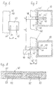
- the lower cross members 21 (at least one of them, depending on However, use several or all of them) with one in the direction directed against the front sides 13 of the carrier 10 and above their level E, shown in FIG. 2 Channel 29 provided.
- FIGS. 3 to 5 In the groove 29 one of FIGS. 3 to 5 is evident Base 30 hung, the groove 29 with advantage Damping means not shown is.
- the frame-like base 30 is similar to the carrier 10 provided with height-adjustable swivel feet 31.
- box elements placed in Fig. 3, 4 and 5 are generally designated 35.
- FIG. 4 shows a box element 35, in which is a sink with more sanitary installations is installed.
- a worktop 36 is supported on one of these box elements 35 (according to FIG. 4 on the middle box element 35 ') .
- additional auxiliary work surfaces having pivot elements 37 around a vertical Axis pivotally arranged (Fig. 4).
- the worktop 36 can also, for example, with an induction hob be equipped (not shown); she can also have a different, for example rectangular, shape, than shown in Fig. 4.
- the wall cladding elements 41 designed as plates; the wall elements 40, however, can be designed in a wide variety of forms his. So it can be box-shaped or frame-shaped Act wall elements 40a or trays 40b; to where appropriate Niche elements with lighting elements 40c to 40d elements with drying rods for Kitchen towels to a fume hood 40e to turn with Supported wall elements 40f and many others.
- Wall elements can also be provided with hook elements Bars or pipes 40g or guide rails in the hook openings 20 be hooked.
- the shown in Fig. 4, in the horizontal direction over the entire wall width extending rods 40g serve, for example, themselves Guide rails for sliding doors 40h.
- the carrier 10 suspended wall element 40g 3 can e.g. also with a flap lockable discharge channel can be provided, which in a Containers arranged in the box element 35, for example Green waste container opens.
- the wall or wall cladding elements 40, 41 are with at least two each, but preferably with four or more Provided hook elements 43, the shape of Fig. 6 and 7th can be seen. 6, this has on the wall element 40 for example screwed-on angular hook element 43 two vertically a distance apart directed hook recesses 44, 45 with which the Wall element 40 optionally in the hook openings 20 of the carrier 10 can be hung. 7 is used as an example shown as a wall element 40 with the first hook recesses 44 into the hook openings 20 of two neighboring ones Carrier 10 is suspended.
- FIG. 7 wall elements open towards the rear towards the building wall 40, however, with the second hook recesses 45 hooked into the hook openings 20, as in the example of a wall element 40 ′′ is shown in FIG. 7.
- the carrier 10 of the distance between the two hook recesses 44, 45 corresponding distance a available, which is also the Thickness of a wall covering element 41 corresponds.
- the wall elements 40 which are open to the rear can be or e.g. Shelves hung in front of the wall cladding elements 41 and come to the plant.
- a hook opening 20 can in the illustrated embodiment each two adjacent wall elements 40, z. B. wall elements 40, 40 'according to FIG. 7, are hung.
- the width b of the wall elements 40 essentially corresponds the distance b of the flanks facing each other Hook openings 20 of two adjacent supports 10, so that between two suspended wall elements 40, 40 'and 40, 40 '' a vertical gap 48 is formed, the Width in Fig. 7 is denoted by s.
- the carrier 10 By arranging the carrier 10 at a distance from the Building wall 14 is suspended between those in the carrier 10 Wall or wall cladding elements 40, 41 and the building wall 14 forms a cavity 50 (see FIG. 3 and 5) which is available for various installations stands.
- the device thus forms one of the building walls 14 pretext.
- the wall elements 40 can, however also be designed in such a way that it can be used with a Protruding part between the carriers 10 into the cavity 50, as it e.g. with the one shown in FIG. 3 and already mentioned wall element 40g is the case.
- In the cavity 50 can also be a rear section of a fume hood, for example be arranged.
- the worktop supported on one of the box elements 35 36 can also be equipped with hook elements and additionally hooked into the hook openings 20 of the carrier 10 be (not shown in the drawing).
- the wall or wall cladding elements 40, 41 preferably from flat hollow profiles 51 Made from recyclable plastic with continuous Recesses 53 are provided. To increase the The recesses 53 with a slat-like stability Wood core 52 filled. The individual parts of the wall elements 40 are preferably screwed together.
- the kitchen wall device according to the invention can be individual can be built in various configurations.
- the assembly is extremely easy. It is also an easy one Disassembly and reconstruction of the kitchen wall equipment possible, especially when renovating or moving is important.
Abstract
Description
Die Erfindung betrifft eine Einrichtung für individuelle
Gestaltung einer Küchenwand gemäss dem Oberbegriff des
Anspruches 1.The invention relates to a device for individual
Design of a kitchen wall according to the generic term of
Eine Einrichtung dieser Art ist beispielsweise aus DE-U-296 00 309 bekannt. Diese Einrichtung weist mehrere im vorbestimmten Abstand nebeneinander angeordnete vertikale Träger auf, die aus Trägeverstärkern in Form von Formplatten beispielsweise aus Holz sowie aus in die Trägeverstärker eingelassenen, metallenen Befestigungsprofilen bestehen. Die Befestigungsprofile, deren Vorderseiten in einer Ebene liegen, sind am Boden abgestützt. Die Trägerverstärker sind über Wandhalterungen an an der Gebäudewand angebrachten horizontalen Wandschienen befestigt. Die Befestigungsprofile sind mit diversen Befestigungs- und Führungsbereichen für die Wandelemente ausgestattet. Sie weisen einen nach vorne offenen U-förmigen Teil auf, dessen Grundfläche mit einer Vielzahl von in Längsrichtung der Träger in einem bestimmten Rastermass angeordneten Hakenöffnungen versehen ist. Zwischen die Schenkel des U-förmigen Teiles können Hakenelemente einer Korpuswange eingeführt und in Hakenöffnungen eingehängt werden. Die Korpuswange deckt dabei die Hakenöffnungen des betreffenden Befestigungsprofils ab. Zum Anbringen eines Wandverkleidungselementes müssen die Schenkel des U-förmigen Teiles an entsprechender Stelle mit Trägerschlitzen versehen sein, in die ein zur Vorderseite paralleler Verkleidungsträger einhängbar ist. Das Wandverkleidungselement wird dann auf den Verkleidungsträger aufgehängt. Die Küchenwandeinrichtung sowie die Montage derselben ist kompliziert im Aufbau und in den Gestaltungsmöglichkeiten eingeschränkt, und es sind separate Teile zum Anbringen der Wandelemente notwendig. A device of this type is for example from DE-U-296 00 309 known. This facility has several im predetermined distance next to each other vertical Beams that consist of reinforcement in the form of shaped plates for example made of wood as well as in the support amplifier embedded, metallic fastening profiles. The Fastening profiles, the front sides in one plane are supported on the ground. The carrier amplifiers are via wall brackets attached to the building wall horizontal wall rails attached. The fastening profiles are with various fastening and guide areas for the Wall elements equipped. They point you forward open U-shaped part, whose base with a Variety of in the longitudinal direction of the carrier in a particular Pitch arranged hook openings is provided. Between the legs of the U-shaped part can be hook elements Body cheek inserted and hooked into hook openings become. The body cheek covers the hook openings of the relevant fastening profile. To attach one Wall cladding element must have the legs of the U-shaped Provide part at the appropriate place with carrier slots into a panel carrier parallel to the front can be attached. The wall covering element is then hung on the fairing support. The kitchen wall device and the assembly of the same is complicated in Structure and limited in the design options, and there are separate parts for attaching the wall elements necessary.
Der vorliegenden Erfindung liegt die Aufgabe zugrunde, eine einfach und den individuellen Bedürfnissen entsprechend montierbare Einrichtung der eingangs genannten Art mit vielfältigen Gestaltungsmöglichkeiten zu schaffen.The present invention has for its object a simple and according to individual needs mountable device of the type mentioned to create diverse design options.
Diese Aufgabe wird erfindungsgemäss durch eine Einrichtung
mit den Merkmalen des Anspruches 1 gelöst.According to the invention, this object is achieved by a device
solved with the features of
Die erfindungsgemässe Einrichtung bringt auch den Vorteil einer einfachen Demontage sowie eines einfachen Wiederaufbaus der Küchenwandeinrichtung beispielsweise bei Renovationen oder beim Umzug. Sie ermöglicht eine kostengünstige Aufputzmontage der Anschlüsse und Instalationen.The device according to the invention also has the advantage a simple disassembly and a simple reconstruction the kitchen wall unit, for example during renovations or when moving. It enables inexpensive Surface mounting of the connections and installations.
Besondere Weitergestaltungen der erfindungsgemässen Einrichtung bilden Gegenstand der abhängigen Ansprüche.Special refinements of the device according to the invention form the subject of the dependent claims.
Die Erfindung wird nun anhand der Zeichnung näher erläutert.The invention will now be explained in more detail with reference to the drawing.
Es zeigen rein schematisch:
- Fig. 1
- ein Ausführungsbeispiel eines Trägerrahmens für eine Küchenwandeinrichtung in Frontansicht;
- Fig. 2
- einen Schnitt nach Linie II-II in Fig. 1;
- Fig. 3
- eine der Fig. 2 entsprechende Darstellung einer Küchenwandeinrichtung in einer ersten Ausführungsform;
- Fig. 4
- in perspektivischer Explosionsdarstellung eine weitere mögliche Ausführungsform einer Küchenwandeinrichtung;
- Fig. 5
- einen Vertikalschnitt durch eine Küchenwandeinrichtung mit eingebauten sanitären Instalationen;
- Fig. 6
- einen Teil eines Wandelementes in Seitenansicht;
- Fig. 7
- das Wandelement nach Fig. 6 in Draufsicht; und
- Fig. 8
- einen Teil eines Wandelementes im Querschnitt.
- Fig. 1
- an embodiment of a support frame for a kitchen wall device in front view;
- Fig. 2
- a section along line II-II in Fig. 1;
- Fig. 3
- one of FIG 2 corresponding representation of a kitchen wall device in a first embodiment.
- Fig. 4
- in a perspective exploded view another possible embodiment of a kitchen wall device;
- Fig. 5
- a vertical section through a kitchen wall device with built-in sanitary installations;
- Fig. 6
- part of a wall element in side view;
- Fig. 7
- 6 in top view; and
- Fig. 8
- a part of a wall element in cross section.
Gemäss Fig. 1 und 2 umfasst ein Trägerrahmen 1 für eine
Küchenwandeinrichtung mehrere im vorbestimmten Abstand nebeneinander
angeordnete, vertikale Träger 10, die über
Drehfüsse 11 am Boden 12 abgestützt sind. Die Träger 10
sind vorzugsweise durch quadratische Hohlprofile aus Metall
gebildet. Wie aus Fig. 2 ersichtlich sind die Träger
10 in einem Abstand von der Gebäudewand 14 angeordnet und
über Distanzelemente 15 an dieser befestigt. Es wäre allerdings
auch durchaus möglich, die Träger 10 an der Decke
zu befestigen. Die Vorderseiten 13 der Träger 10 liegen in
einer Ebene E.1 and 2 comprises a
Die Vorderseiten 13 der Träger 10 sind mit einer Vielzahl
von in Längsrichtung der Träger 20 in einem bestimmten Rastermass
angeordneten Hakenöffnungen 20 versehen. Beispielsweise
sind die Hakenöffnungen 20 in einem Rasterabstand
von 12 cm voneinander entfernt. In die Hakenöffnungen
20 können - wie weiter unten beschrieben wird - verschiedene
Wand- bzw. Wandverkleidungselemente eingehängt
werden. In Fig. 1 und 2 ist der Grundraster des Trägerrahmens
1 mit strichpunktierten Linien x, y angedeutet.The
Die Träger 10 sind mittels der Drehfüsse 11 über die Länge
eines Raster- bzw. Hakenöffnungabstandes stufenlos höhenverstellbar
und in der gewünschten Position mittels den
Drehfüssen zugeordneten Kontermuttern (in der Zeichnung
nicht dargestellt) feststellbar. Die Höhenverstellbarkeit
der Träger 10 könnte allerdings auch in einer anderen bekannten
Art und Weise realisiert werden.The
Zwei benachbarte Träger 10 sind jeweils über mindestens
zwei Querträger 21, 22 miteinander verbunden, von denen
der eine im unteren, der andere im oberen Bereich der Träger
10 angeordnet ist. Zwecks Stabilitätserhöhung können
jedoch nach Bedarf an besonders zu belastenden Stellen zusätzliche
Querträger 23 angebracht werden (vgl. Fig. 1).
Zur Verbindung der Querträger 21, 22, 23 und der Träger 10
sind weitere Hakenöffnungen in den Trägern 10, beispielsweise
in Seitenwänden 24, 25 der Träger 10, angefertigt,
in welche die Querträger 21, 22, 23 mit ihren in der
Zeichnung nicht näher dargestellten Hakenelementen eingehängt
werden, die ähnlich wie die Hakenelemente der Wand-
bzw. Wandverkleidungselemente ausgebildet sind, jedoch im
Gegensatz zu den letzteren jeweils in zwei übereinander
liegende Hakenöffnungen eingreifen, um ausreichende Querstabilität
des Trägerrahmens 1 zu sichern.Two
Die unteren Querträger 21 (zumindest einer davon, je nach
Gebrauch jedoch mehrere oder alle) sind mit einer in Richtung
gegen die Vorderseiten 13 der Träger 10 gerichteten
und über deren Ebene E vorstehenden, aus Fig. 2 ersichtlichen
Rinne 29 versehen.The lower cross members 21 (at least one of them, depending on
However, use several or all of them) with one in the direction
directed against the
Fig. 3, 4 und 5 zeigen verschiedene Möglichkeiten für die
Gestaltung einer Küchenwandeinrichtung mit dem vorstehend
beschriebenen Trägerrahmen 1.3, 4 and 5 show different possibilities for the
Design of a kitchen wall device with the above
described
In die Rinne 29 wird ein aus Fig. 3 bis 5 ersichtlicher
Sockel 30 eingehängt, wobei die Rinne 29 mit Vorteil mit
nicht näher dargestellten Dämpfungsmitteln ausgestattet
ist. Der rahmenartige Sockel 30 ist ähnlich wie die Träger
10 mit höhenverstellbaren Drehfüssen 31 versehen. Auf den
Sockel 30 werden Kastenelemente aufgesetzt, die in Fig. 3,
4 und 5 generell mit 35 bezeichnet sind.In the
Wie in Fig. 4 angedeutet (in dieser Figur sind einfachheitshalber
die mit der Rinne 29 versehenen unteren Quärträger
21 nicht dargestellt) kann es sich dabei um mit
Schubladen versehene oder andere Kastenelemente handeln,
oder aber auch um einen Kochherd, einen Backofen, einen
Geschirrspüler etc. Fig. 5 zeigt ein Kastenelement 35, in
welchem ein Abwaschbecken mit sanitäreren Instalationen
eingebaut ist. As indicated in Fig. 4 (in this figure, for the sake of simplicity
the lower Quärträger with the
Auf einem dieser Kastenelemente 35 (gemäss Fig. 4 auf dem
mittleren Kastenelement 35') ist eine Arbeitsplatte 36 abgestützt.
Zur Erweiterung der verfügbaren Arbeitsfläche
können unterhalb der Arbeitsplatte 36 zusätzliche Hilfsarbeitsflächen
aufweisende Schwenkelemente 37 um eine vertikale
Achse schwenkbar angeordnet sein (Fig. 4). Die Arbeitsplatte
36 kann auch beispielsweise mit einem Induktionskochfeld
(nicht dargestellt) ausgerüstet sein; sie kann
auch eine andere, beispielsweise rechteckige Form aufweisen,
als in Fig. 4 dargestellt.On one of these box elements 35 (according to FIG. 4 on the
middle box element 35 ') a
Oberhalb der die Arbeitsfläche bildenden Arbeitsplatte 36
sind gemäss Fig. 3, 4 und 5 mit Hakenelementen versehene
Wand- bzw. Wandverkleidungselemente 40 bzw. 41 angeordnet
und mit den Hakenelementen in die Hakenöffnungen 20 der
Träger 10 eingehängt. Die Hakenelemente selber sind in
Fig. 3 bis 5 nicht dargestellt und werden weiter unten anhand
der Fig. 6 und 7 beschrieben.Above the
Wie in Fig. 4 schematisch dargestellt sind die Wandverkleidungselemente
41 als Platten ausgebildet; die Wandelemente
40 können hingegen in verschiedenster Form ausgestaltet
sein. So kann es sich um kasten- oder rahmenförmige
Wandelemente 40a oder um Tablare 40b handeln; um gegebenenfalls
Beleuchtungselemente aufweisende Nischenelemente
40c, um Elemente 40d mit Tröcknungsstangen für
Küchentücher, um einen Dampfabzug 40e, um mit drehbaren
Trägern versehene Wandelemente 40f und viele andere. Als
Wandelemente können auch mit Hakenelementen versehene
Stangen bzw. Rohre 40g oder Führungsschienen in die Hakenöffnungen
20 eingehängt sein. Die in Fig. 4 dargestellten,
in horizontaler Richtung sich über die gesamte Wandbreite
erstreckenden Stangen 40g dienen beispielsweise selber als
Führungsschienen für Schiebetüren 40h.As shown schematically in Fig. 4 are the
Ein unmittelbar oberhalb der Arbeitsplatte 36 in die Hakenöffnungen
20 der Träger 10 eingehängtes Wandelement 40g
kann gemäss Fig. 3 z.B. auch mit einem mittels einer Klappe
abschliessbaren Abwurfkanal versehen sein, der in einen
im Kastenelement 35 angeordneten Behälter, beispielsweise
Grünabfallbehälter mündet.One immediately above the
Die Wand- bzw. Wandverkleidungselemente 40, 41 sind mit
wenigstens je zwei, vorzugsweise jedoch mit vier oder mehr
Hakenelementen 43 versehen, deren Form aus Fig. 6 und 7
ersichtlich ist. Gemäss Fig. 6 weist das am Wandelement 40
beispielsweise angeschraubte winkelförmige Hakenelement 43
zwei in einem Abstand a voneinander entfernte, vertikal
gerichtete Hakenausnehmungen 44, 45 auf, mit welchen das
Wandelement 40 wahlweise in die Hakenöffnungen 20 der Träger
10 eingehängt werden kann. In Fig. 7 wird als Beispiel
dargestellt, wie ein Wandelement 40 mit den ersten Hakenausnehmungen
44 in die Hakenöffnungen 20 zweier benachbarten
Träger 10 eingehängt ist. In diesem Fall kommt eine
hintere, den Trägern 10 zugewandte Fläche 46 des Wandelementes
40 direkt an den Vorderseiten 13 der Träger 10 zur
Anlage, da eine Flanke 44' der Hakenausnehmung 44 bündig
mit der Fläche 46 ist. Auf diese Weise werden diejenigen
Wandelemente 40 aufgehängt, die mit einer hinteren, die
Gebäudewand 14 abdeckenden Rückwand versehen sind (z.B.
Wandkasten etc.), sowie alle plattenförmigen Wandverkleidungselemente
41 (die letzteren können im Prinzip nur mit
einfachen, nur die ersten Hakenausnehmung 44 aufweisenden
Hakenelementen ausgerüstet sein). The wall or
Nach hinten in Richtung zur Gebäudewand 14 offene Wandelemente
40 werden hingegen mit den zweiten Hakenausnehmungen
45 in die Hakenöffnungen 20 eingehängt, wie am Beispiel
eines Wandelementes 40'' in Fig. 7 gezeigt wird. In diesem
Fall ist zwischen der dem Träger 10 zugewandten hinteren
Fläche 46'' des Wandelementes 40'' und der Vorderseite 13
des Trägers 10 der dem Abstand beider Hakenausnehmungen
44, 45 entsprechende Abstand a vorhanden, der auch der
Dicke eines Wandverkleidungselementes 41 entspricht. Auf
diese Weise können die nach hinten offenen Wandelemente 40
oder z.B. Tablare vor die Wandverkleidungselemente 41 aufgehängt
werden und an diesen zur Anlage kommen.14 wall elements open towards the rear towards the
In eine Hakenöffnung 20 können bei der dargestellten Ausführungsform
jeweils zwei benachbarte Wandelemente 40, z.
B. Wandelemente 40, 40' nach Fig. 7, eingehängt werden.
Die Breite b der Wandelemente 40 entspricht im wesentlichen
dem Abstand b der einander zugewandten Flanken der
Hakenöffnungen 20 zweier benachbarten Träger 10, so dass
zwischen zwei eingehängten Wandelementen 40, 40' bzw. 40,
40'' jeweils ein vertikaler Spalt 48 gebildet ist, dessen
Breite in Fig. 7 mit s Bezeichnet ist. Dadurch sind bei
bereits eingehängten Wand- bzw. Wandverkleidungselementen
40, 41 die noch freien, vertikal übereinander ligenden Hakenöffnungen
20 der Träger 10 zum Einhängen weiterer Wandelemente
40 zugänglich.A
Durch die Anordnung der Träger 10 in einem Abstand von der
Gebäudewand 14 wird zwischen den in die Träger 10 eingehängten
Wand- bzw. Wandverkleidungselementen 40, 41 und
der Gebäudewand 14 ein Hohlraum 50 gebildet (vgl. Fig. 3
und 5), der für verschiedene Instalationen zur Verfügung
steht. Die Einrichtung bildet somit eine der Gebäudewand
14 vorgesetzte Vorwand. Die Wandelemente 40 können allerdings
auch derart ausgebildet sein, dass sie mit einem
Teil zwischen den Trägern 10 in den Hohlraum 50 hineinragen,
wie es z.B. bei dem in Fig. 3 dargestellten und bereits
erwähnten Wandelement 40g der Fall ist. Im Hohlraum
50 kann beispielsweise auch ein Hinterbau eines Dampfabzuges
angeordnet sein.By arranging the
Die auf einem der Kastenelemente 35 abgestützte Arbeitsplatte
36 kann ebenfalls mit Hakenelementen ausgerüstet
und in die Hakenöffnungen 20 der Träger 10 zusätzlich eingehängt
sein (in der Zeichnung nicht dargestellt).The worktop supported on one of the
Gemäss Fig. 8 werden die Wand- bzw. Wandverkleidungselemente
40, 41 vorzugsweise aus flächigen Hohlprofilen 51
aus rezyklierbarem Kunststoff hergestellt, die mit durchgehenden
Ausnehmungen 53 versehen sind. Zur Erhöhung der
Stabilität werden die Ausnehmungen 53 mit einem lattenartigen
Holzkern 52 gefüllt. Die einzelnen Teile der Wandelemente
40 werden vorzugsweise miteinander verschraubt.8, the wall or
Ausser der in Fig. 7 dargestellten Ausführungsform, bei
welcher zwei Hakenelemente 43 benachbarter Wand- bzw.
Wandverkleidungselemente 40, 41 in eine Hakenöffnung 20
einhängbar sind, wäre es auch möglich, die Hakenöffnungen
zur Aufnahme von mehreren Hakenelementen, oder aber auch
zur Aufnahme nur eines Hakenelements auszubilden. Im letzteren
Fall müssten Hakenelemente benachbarter Wandelemente
in verschieden hoch angeordnete Hakenöffnungen eingehängt
werden.Except for the embodiment shown in Fig. 7, at
which two
Die erfindungsgemässe Küchnewandeinrichtung kann individuell in verschiedensten Ausgestaltungen aufgebaut werden. The kitchen wall device according to the invention can be individual can be built in various configurations.
Die Montage ist extrem einfach. Es ist auch eine einfache Demontage sowie ein Wiederaufbau der Küchenwandeinrichtung möglich, was insbesondere bei Renovationen oder beim Umzug von Bedeutung ist.The assembly is extremely easy. It is also an easy one Disassembly and reconstruction of the kitchen wall equipment possible, especially when renovating or moving is important.
Claims (15)
- Arrangement for individual configuration of a kitchen wall, having a plurality of vertical supports (10) which are arranged beside one another at a predetermined distance, are supported on the floor (12) and are fixed to a building wall (14), whose front sides (13) lie in one plane (E) and which are provided with a multiplicity of hook openings (20) which are arranged in the longitudinal direction of the supports (10) at a specific grid dimension and into which wall elements (40) provided with hook elements (43) can be hooked from the front, characterized in that the supports (10) are fixed to the building wall (14) and/or a ceiling and are formed by hollow profiles which are preferably square and provided on the front side (13) with the hook openings (20), into which hook openings (20) wall cladding elements (41) can also be hooked, the width (b) of the wall or wall cladding elements (40, 41) substantially corresponding to the distance between the mutually facing side flanks of hook openings (20) of two supports (10) and, between two hooked-in, horizontally adjacent wall or wall cladding elements (40, 41), there being a vertical gap (48) which makes hook openings (20) made in the front side (13) of the supports (10) accessible, and two adjacent supports (10) being connected to each other at least via an upper and a lower horizontal cross support (22, 21), which is or are hooked into further hook openings in the supports (10).
- Arrangement according to Claim 1, characterized in that the hook elements (43) of two horizontally adjacent wall or wall cladding elements (40, 41) can be hooked into the same hook opening (20).
- Arrangement according to Claim 1 or 2, characterized in that the wall or wall cladding elements (40, 41) are arranged above a worktop (36).
- Arrangement according to Claim 3, characterized in that the worktop (36) is associated with at least one box element (35) which stands on a plinth (30), the plinth (30) supported on the floor being arranged on at least one lower cross support (21).
- Arrangement according to Claim 4, characterized in that at least one of the lower cross supports (21) has a channel (29) which projects in the direction towards the front sides (13) of the supports (10), beyond their plane (E) , and into which the plinth (30) is hooked.
- Arrangement according to one of Claims 1 to 5, characterized in that the supports (10) are provided with an adjustable-height foot (11).
- Arrangement according to one of Claims 1 to 6, characterized in that the supports (10) are arranged at a distance from the building wall (14) and, together with the wall or wall cladding elements (40, 41) hooked into the said supports, are intended to form a cavity (50) for services.
- Arrangement according to Claim 7, characterized in that a wall element (40) hooked into two supports (10) projects through between the supports (10) into the cavity (50).
- Arrangement according to one of Claims 1 to 8, characterized in that the wall cladding elements (41) are constructed as boards.
- Arrangement according to one of Claims 1 to 9, characterized in that the wall elements (40) are constructed like frames or boxes.
- Arrangement according to one of Claims 1 to 9, characterized in that the wall elements (40) are constructed as shelves.
- Arrangement according to one of Claims 1 to 9, characterized in that the wall elements (40) comprise horizontal guide rails or guide rods which extend between two or more supports (10) and are intended to guide transversely displaceable elements such as sliding doors.
- Arrangement according to one of Claims 1 to 12, characterized in that the hook elements (43) associated with the wall elements (40) have two spaced-apart hook cutouts (44, 45) where, as the wall element (40) is being hooked with one hook cutout (44) into the hook opening (20) of the support (10), the wall element (40) comes into direct contact with the support (10), while as the wall element (40) is being hooked in with the other hook cutout (45) it can come into contact with a wall cladding element (41) which has already been hooked in.
- Arrangement according to one of Claims 3 to 13, characterized in that in order to extend the working area, a pivoting element (37) provided with an auxiliary working area is arranged underneath the worktop (36) such that it can be pivoted about a vertical axis.
- Arrangement according to one of Claims 1 to 14, characterized in that the wall or wall cladding elements (40, 41) are produced from recyclable material, preferably from flat hollow profiles made of plastic and provided with continuous cutouts (53), it being possible for the cutouts (53) to be filled with a slat-like wooden core (52) in order to increase the stability.
Priority Applications (4)
| Application Number | Priority Date | Filing Date | Title |
|---|---|---|---|
| EP97101084A EP0855158B1 (en) | 1997-01-24 | 1997-01-24 | Arrangement for individual styling of kitchen wall cupboards |
| DE59704295T DE59704295D1 (en) | 1997-01-24 | 1997-01-24 | Furnishing for individual design of a kitchen wall |
| DK97101084T DK0855158T3 (en) | 1997-01-24 | 1997-01-24 | Device for individual design of a kitchen wall |
| AT97101084T ATE204144T1 (en) | 1997-01-24 | 1997-01-24 | DEVICE FOR INDIVIDUAL DESIGN OF A KITCHEN WALL |
Applications Claiming Priority (1)
| Application Number | Priority Date | Filing Date | Title |
|---|---|---|---|
| EP97101084A EP0855158B1 (en) | 1997-01-24 | 1997-01-24 | Arrangement for individual styling of kitchen wall cupboards |
Publications (2)
| Publication Number | Publication Date |
|---|---|
| EP0855158A1 EP0855158A1 (en) | 1998-07-29 |
| EP0855158B1 true EP0855158B1 (en) | 2001-08-16 |
Family
ID=8226402
Family Applications (1)
| Application Number | Title | Priority Date | Filing Date |
|---|---|---|---|
| EP97101084A Expired - Lifetime EP0855158B1 (en) | 1997-01-24 | 1997-01-24 | Arrangement for individual styling of kitchen wall cupboards |
Country Status (4)
| Country | Link |
|---|---|
| EP (1) | EP0855158B1 (en) |
| AT (1) | ATE204144T1 (en) |
| DE (1) | DE59704295D1 (en) |
| DK (1) | DK0855158T3 (en) |
Cited By (3)
| Publication number | Priority date | Publication date | Assignee | Title |
|---|---|---|---|---|
| EP1219205A2 (en) * | 2000-12-29 | 2002-07-03 | ALNO Aktiengesellschaft | Kitchen with kitchen units having a fixed profiled body |
| EP1366691A1 (en) | 2002-05-29 | 2003-12-03 | bulthaup GmbH & Co. KG | Kitchen furniture system |
| WO2004014185A2 (en) * | 2002-08-01 | 2004-02-19 | Bernhard Michael Kaluza | Assembly system for furniture and method for assembling furniture |
Families Citing this family (2)
| Publication number | Priority date | Publication date | Assignee | Title |
|---|---|---|---|---|
| DE10020772C1 (en) * | 2000-04-28 | 2002-01-17 | Albert Kirschner | Bathroom furniture arrangement has holder device with two h-frames connected by transverse supports with furniture base fixed between h-frames and hanging cupboards fixed to top of long part of h |
| ITAN20050004A1 (en) * | 2005-01-14 | 2006-07-15 | Margaritelli Italia Spa | MODULAR STRUCTURE MODELING COUNTERPARK |
Family Cites Families (4)
| Publication number | Priority date | Publication date | Assignee | Title |
|---|---|---|---|---|
| BE665679A (en) * | ||||
| DE1303175B (en) * | 1966-04-23 | 1971-07-01 | Hettlage Kg | Frame for collapsible shelves, cubicles, boxes, etc. like |
| DK35094A (en) * | 1994-03-28 | 1995-09-29 | Am System Silkeborg As | Inventory System |
| DE29600309U1 (en) * | 1996-01-10 | 1996-03-07 | Wellmann Gustav Gmbh & Co Kg | Wall mounting device |
-
1997
- 1997-01-24 DK DK97101084T patent/DK0855158T3/en active
- 1997-01-24 DE DE59704295T patent/DE59704295D1/en not_active Expired - Fee Related
- 1997-01-24 AT AT97101084T patent/ATE204144T1/en not_active IP Right Cessation
- 1997-01-24 EP EP97101084A patent/EP0855158B1/en not_active Expired - Lifetime
Cited By (3)
| Publication number | Priority date | Publication date | Assignee | Title |
|---|---|---|---|---|
| EP1219205A2 (en) * | 2000-12-29 | 2002-07-03 | ALNO Aktiengesellschaft | Kitchen with kitchen units having a fixed profiled body |
| EP1366691A1 (en) | 2002-05-29 | 2003-12-03 | bulthaup GmbH & Co. KG | Kitchen furniture system |
| WO2004014185A2 (en) * | 2002-08-01 | 2004-02-19 | Bernhard Michael Kaluza | Assembly system for furniture and method for assembling furniture |
Also Published As
| Publication number | Publication date |
|---|---|
| DK0855158T3 (en) | 2001-11-19 |
| ATE204144T1 (en) | 2001-09-15 |
| EP0855158A1 (en) | 1998-07-29 |
| DE59704295D1 (en) | 2001-09-20 |
Similar Documents
| Publication | Publication Date | Title |
|---|---|---|
| DE3390404C2 (en) | ||
| DE4217501A1 (en) | Mobile table unit for medical equipment - has shelves connected to stands on each side, and has fillets with connectors running around shelf, being held in position by stops | |
| EP0855158B1 (en) | Arrangement for individual styling of kitchen wall cupboards | |
| EP1003401B1 (en) | Twinned kitchen furniture system, in particular to be wall-mounted with or without bottom support | |
| DE69907078T2 (en) | Illuminated shelf | |
| DE2625202C3 (en) | Household appliance, e.g. dishwasher, with a base recess on the front | |
| DE10163182A1 (en) | Fastening element for fastening a household appliance | |
| EP0133707B1 (en) | Shoe cabinet with vertically adjustable shelves | |
| DE4317814C2 (en) | Assembly floor with at least one floor plate | |
| DE3231802C2 (en) | ||
| EP0517938B1 (en) | Modular construction system | |
| DE202019101127U1 (en) | Modular furniture | |
| DE19956951C2 (en) | Workplace furniture with a furniture frame made of vertical columns and crossbars | |
| DE2721077C3 (en) | Kitchen equipment from prefabricated elements | |
| EP1321072A1 (en) | Component to construct a rack, furniture, a column or similar | |
| EP1366691B1 (en) | Kitchen furniture system | |
| DE10324375A1 (en) | System for fitting-out kitchens, comprises support strips connected to horizontal rails on which furniture and appliances are hung | |
| EP1142509B1 (en) | Rack | |
| DE202020106916U1 (en) | Furniture | |
| DE19827332A1 (en) | Support system for goods, with uprights and fixture elements | |
| DE3927238A1 (en) | HOUSEHOLD APPLIANCE, e.g. DISHWASHER | |
| AT352356B (en) | VARIABLE SPACE LIMITATION | |
| DE2331976C2 (en) | partition wall | |
| DE1950578C3 (en) | Work table, counter or the like that can be varied in shape, length and height | |
| DE202019106201U1 (en) | cabinet |
Legal Events
| Date | Code | Title | Description |
|---|---|---|---|
| PUAI | Public reference made under article 153(3) epc to a published international application that has entered the european phase |
Free format text: ORIGINAL CODE: 0009012 |
|
| AK | Designated contracting states |
Kind code of ref document: A1 Designated state(s): AT BE CH DE DK ES FR GB IT LI LU NL PT SE |
|
| 17P | Request for examination filed |
Effective date: 19980822 |
|
| AKX | Designation fees paid |
Free format text: AT BE CH DE DK ES FR GB IT LI LU NL PT SE |
|
| RBV | Designated contracting states (corrected) |
Designated state(s): AT BE CH DE DK ES FR GB IT LI LU NL PT SE |
|
| 17Q | First examination report despatched |
Effective date: 19991007 |
|
| GRAG | Despatch of communication of intention to grant |
Free format text: ORIGINAL CODE: EPIDOS AGRA |
|
| GRAG | Despatch of communication of intention to grant |
Free format text: ORIGINAL CODE: EPIDOS AGRA |
|
| GRAH | Despatch of communication of intention to grant a patent |
Free format text: ORIGINAL CODE: EPIDOS IGRA |
|
| GRAH | Despatch of communication of intention to grant a patent |
Free format text: ORIGINAL CODE: EPIDOS IGRA |
|
| GRAA | (expected) grant |
Free format text: ORIGINAL CODE: 0009210 |
|
| ITF | It: translation for a ep patent filed |
Owner name: BARZANO' E ZANARDO MILANO S.P.A. |
|
| AK | Designated contracting states |
Kind code of ref document: B1 Designated state(s): AT BE CH DE DK ES FR GB IT LI LU NL PT SE |
|
| REF | Corresponds to: |
Ref document number: 204144 Country of ref document: AT Date of ref document: 20010915 Kind code of ref document: T |
|
| REG | Reference to a national code |
Ref country code: CH Ref legal event code: NV Representative=s name: PATENTANWAELTE SCHAAD, BALASS, MENZL & PARTNER AG Ref country code: CH Ref legal event code: EP |
|
| REF | Corresponds to: |
Ref document number: 59704295 Country of ref document: DE Date of ref document: 20010920 |
|
| GBT | Gb: translation of ep patent filed (gb section 77(6)(a)/1977) |
Effective date: 20011003 |
|
| PG25 | Lapsed in a contracting state [announced via postgrant information from national office to epo] |
Ref country code: PT Free format text: LAPSE BECAUSE OF FAILURE TO SUBMIT A TRANSLATION OF THE DESCRIPTION OR TO PAY THE FEE WITHIN THE PRESCRIBED TIME-LIMIT Effective date: 20011116 |
|
| REG | Reference to a national code |
Ref country code: DK Ref legal event code: T3 |
|
| ET | Fr: translation filed | ||
| REG | Reference to a national code |
Ref country code: GB Ref legal event code: IF02 |
|
| PG25 | Lapsed in a contracting state [announced via postgrant information from national office to epo] |
Ref country code: ES Free format text: LAPSE BECAUSE OF FAILURE TO SUBMIT A TRANSLATION OF THE DESCRIPTION OR TO PAY THE FEE WITHIN THE PRESCRIBED TIME-LIMIT Effective date: 20020228 |
|
| PLBE | No opposition filed within time limit |
Free format text: ORIGINAL CODE: 0009261 |
|
| STAA | Information on the status of an ep patent application or granted ep patent |
Free format text: STATUS: NO OPPOSITION FILED WITHIN TIME LIMIT |
|
| 26N | No opposition filed | ||
| PGFP | Annual fee paid to national office [announced via postgrant information from national office to epo] |
Ref country code: NL Payment date: 20021227 Year of fee payment: 7 Ref country code: GB Payment date: 20021227 Year of fee payment: 7 |
|
| PGFP | Annual fee paid to national office [announced via postgrant information from national office to epo] |
Ref country code: LU Payment date: 20021230 Year of fee payment: 7 |
|
| PGFP | Annual fee paid to national office [announced via postgrant information from national office to epo] |
Ref country code: AT Payment date: 20030102 Year of fee payment: 7 |
|
| PGFP | Annual fee paid to national office [announced via postgrant information from national office to epo] |
Ref country code: DK Payment date: 20030106 Year of fee payment: 7 |
|
| PGFP | Annual fee paid to national office [announced via postgrant information from national office to epo] |
Ref country code: SE Payment date: 20030109 Year of fee payment: 7 |
|
| PGFP | Annual fee paid to national office [announced via postgrant information from national office to epo] |
Ref country code: FR Payment date: 20030110 Year of fee payment: 7 |
|
| PGFP | Annual fee paid to national office [announced via postgrant information from national office to epo] |
Ref country code: BE Payment date: 20030123 Year of fee payment: 7 |
|
| PGFP | Annual fee paid to national office [announced via postgrant information from national office to epo] |
Ref country code: DE Payment date: 20030124 Year of fee payment: 7 |
|
| PGFP | Annual fee paid to national office [announced via postgrant information from national office to epo] |
Ref country code: CH Payment date: 20030130 Year of fee payment: 7 |
|
| PG25 | Lapsed in a contracting state [announced via postgrant information from national office to epo] |
Ref country code: LU Free format text: LAPSE BECAUSE OF NON-PAYMENT OF DUE FEES Effective date: 20040124 Ref country code: GB Free format text: LAPSE BECAUSE OF NON-PAYMENT OF DUE FEES Effective date: 20040124 Ref country code: AT Free format text: LAPSE BECAUSE OF NON-PAYMENT OF DUE FEES Effective date: 20040124 |
|
| PG25 | Lapsed in a contracting state [announced via postgrant information from national office to epo] |
Ref country code: SE Free format text: LAPSE BECAUSE OF NON-PAYMENT OF DUE FEES Effective date: 20040125 |
|
| PG25 | Lapsed in a contracting state [announced via postgrant information from national office to epo] |
Ref country code: LI Free format text: LAPSE BECAUSE OF NON-PAYMENT OF DUE FEES Effective date: 20040131 Ref country code: CH Free format text: LAPSE BECAUSE OF NON-PAYMENT OF DUE FEES Effective date: 20040131 Ref country code: BE Free format text: LAPSE BECAUSE OF NON-PAYMENT OF DUE FEES Effective date: 20040131 |
|
| PG25 | Lapsed in a contracting state [announced via postgrant information from national office to epo] |
Ref country code: DK Free format text: LAPSE BECAUSE OF NON-PAYMENT OF DUE FEES Effective date: 20040202 |
|
| BERE | Be: lapsed |
Owner name: BRUNO *PIATTI A.G. Effective date: 20040131 |
|
| PG25 | Lapsed in a contracting state [announced via postgrant information from national office to epo] |
Ref country code: NL Free format text: LAPSE BECAUSE OF NON-PAYMENT OF DUE FEES Effective date: 20040801 |
|
| PG25 | Lapsed in a contracting state [announced via postgrant information from national office to epo] |
Ref country code: DE Free format text: LAPSE BECAUSE OF NON-PAYMENT OF DUE FEES Effective date: 20040803 |
|
| EUG | Se: european patent has lapsed | ||
| REG | Reference to a national code |
Ref country code: DK Ref legal event code: EBP |
|
| GBPC | Gb: european patent ceased through non-payment of renewal fee |
Effective date: 20040124 |
|
| REG | Reference to a national code |
Ref country code: CH Ref legal event code: PL |
|
| PG25 | Lapsed in a contracting state [announced via postgrant information from national office to epo] |
Ref country code: FR Free format text: LAPSE BECAUSE OF NON-PAYMENT OF DUE FEES Effective date: 20040930 |
|
| NLV4 | Nl: lapsed or anulled due to non-payment of the annual fee |
Effective date: 20040801 |
|
| REG | Reference to a national code |
Ref country code: FR Ref legal event code: ST |
|
| PG25 | Lapsed in a contracting state [announced via postgrant information from national office to epo] |
Ref country code: IT Free format text: LAPSE BECAUSE OF NON-PAYMENT OF DUE FEES;WARNING: LAPSES OF ITALIAN PATENTS WITH EFFECTIVE DATE BEFORE 2007 MAY HAVE OCCURRED AT ANY TIME BEFORE 2007. THE CORRECT EFFECTIVE DATE MAY BE DIFFERENT FROM THE ONE RECORDED. Effective date: 20050124 |