EP0854969B1 - Dampfturbinenanlage - Google Patents
Dampfturbinenanlage Download PDFInfo
- Publication number
- EP0854969B1 EP0854969B1 EP96944570A EP96944570A EP0854969B1 EP 0854969 B1 EP0854969 B1 EP 0854969B1 EP 96944570 A EP96944570 A EP 96944570A EP 96944570 A EP96944570 A EP 96944570A EP 0854969 B1 EP0854969 B1 EP 0854969B1
- Authority
- EP
- European Patent Office
- Prior art keywords
- steam
- steam turbine
- heat exchanger
- exchanger modules
- feed
- Prior art date
- Legal status (The legal status is an assumption and is not a legal conclusion. Google has not performed a legal analysis and makes no representation as to the accuracy of the status listed.)
- Expired - Lifetime
Links
- XLYOFNOQVPJJNP-UHFFFAOYSA-N water Substances O XLYOFNOQVPJJNP-UHFFFAOYSA-N 0.000 claims abstract description 27
- 238000005192 partition Methods 0.000 claims description 5
- 239000003990 capacitor Substances 0.000 description 2
- 238000010276 construction Methods 0.000 description 2
- 238000009417 prefabrication Methods 0.000 description 1
- 238000005086 pumping Methods 0.000 description 1
- 230000003068 static effect Effects 0.000 description 1
Images
Classifications
-
- F—MECHANICAL ENGINEERING; LIGHTING; HEATING; WEAPONS; BLASTING
- F01—MACHINES OR ENGINES IN GENERAL; ENGINE PLANTS IN GENERAL; STEAM ENGINES
- F01K—STEAM ENGINE PLANTS; STEAM ACCUMULATORS; ENGINE PLANTS NOT OTHERWISE PROVIDED FOR; ENGINES USING SPECIAL WORKING FLUIDS OR CYCLES
- F01K11/00—Plants characterised by the engines being structurally combined with boilers or condensers
- F01K11/02—Plants characterised by the engines being structurally combined with boilers or condensers the engines being turbines
-
- F—MECHANICAL ENGINEERING; LIGHTING; HEATING; WEAPONS; BLASTING
- F01—MACHINES OR ENGINES IN GENERAL; ENGINE PLANTS IN GENERAL; STEAM ENGINES
- F01K—STEAM ENGINE PLANTS; STEAM ACCUMULATORS; ENGINE PLANTS NOT OTHERWISE PROVIDED FOR; ENGINES USING SPECIAL WORKING FLUIDS OR CYCLES
- F01K7/00—Steam engine plants characterised by the use of specific types of engine; Plants or engines characterised by their use of special steam systems, cycles or processes; Control means specially adapted for such systems, cycles or processes; Use of withdrawn or exhaust steam for feed-water heating
- F01K7/34—Steam engine plants characterised by the use of specific types of engine; Plants or engines characterised by their use of special steam systems, cycles or processes; Control means specially adapted for such systems, cycles or processes; Use of withdrawn or exhaust steam for feed-water heating the engines being of extraction or non-condensing type; Use of steam for feed-water heating
- F01K7/40—Use of two or more feed-water heaters in series
-
- Y—GENERAL TAGGING OF NEW TECHNOLOGICAL DEVELOPMENTS; GENERAL TAGGING OF CROSS-SECTIONAL TECHNOLOGIES SPANNING OVER SEVERAL SECTIONS OF THE IPC; TECHNICAL SUBJECTS COVERED BY FORMER USPC CROSS-REFERENCE ART COLLECTIONS [XRACs] AND DIGESTS
- Y02—TECHNOLOGIES OR APPLICATIONS FOR MITIGATION OR ADAPTATION AGAINST CLIMATE CHANGE
- Y02E—REDUCTION OF GREENHOUSE GAS [GHG] EMISSIONS, RELATED TO ENERGY GENERATION, TRANSMISSION OR DISTRIBUTION
- Y02E20/00—Combustion technologies with mitigation potential
- Y02E20/14—Combined heat and power generation [CHP]
Definitions
- the invention relates to a steam turbine system with a number of arranged on a common turbine shaft Pressure stages.
- a steam turbine plant In a steam turbine plant, one is usually one of the Steam turbine downstream condenser below the Steam turbine arranged. Also includes the steam turbine plant for preheating in the steam circuit of the steam turbine led condensate or feed water a variety of Preheating a preheating section (see for example GB-A-273 803).
- a steam turbine plant with a variety of such preheaters for example known from US Pat. No. 5,404,724.
- a Such a steam turbine system is therefore due to the design the steam turbine and due to the large number of structural ones Components require considerable construction effort and takes up a lot of space.
- the assembly effort at Erection of such a steam turbine system particularly high, especially since the steam turbine located above the condenser requires an elaborate supporting structure.
- a steam turbine plant with a number of pressure levels and with one downstream in the axial direction of the turbine shaft arranged capacitor is known from EP-A-206 135.
- the invention is therefore based on the object, a particular one to specify compact steam turbine system, which also in particular is easy to assemble.
- a steam turbine system with a number of on a common Turbine shaft arranged pressure stages, and with one in arranged in the axial direction of the turbine shaft on the downstream side Condenser, as well as with a feed water preheater with a Number of taps with steam from one or each pressure level heatable and arranged in a common housing
- Heat exchanger modules in-line on the feed water side and on the tap steam side are connected in parallel, two each Adjacent heat exchanger modules on the steam side by a Partition separated from each other and on the feed water side a collector are connected.
- the invention is based on the consideration that on the one hand by arranging all relevant structural parts at ground level, especially the steam turbine and the condenser and the feed water preheater of the preheating section, the assembly effort especially when installing a steam turbine system is low.
- the preheating section is particularly space-saving and additional be placed close to the steam turbine.
- a compact design of the preheating section is in turn by a Modular construction of a single feed water preheater achievable.
- Corresponding heat exchanger modules can then be on the feed water side in the manner of a multiplex preheater directly be connected in series so that connecting lines are saved.
- a further reduction in assembly effort is also achieved by the heat exchanger modules in one common housing are arranged.
- a heat exchanger module per se is, for example, from the document DE-A-39 05 066 known.
- a particularly reliable decoupling different pressure levels of the bleed steam from one another is by separating the heat exchanger modules via the respective partition can be reached.
- the pressure levels are Steam turbine and the condenser in a common housing arranged.
- each tap steam supplied is particularly effective to use and thus a particularly high efficiency
- To reach the steam turbine plant is also every heat exchanger module expediently with regard to its design pressure adapted to a pressure level.
- a common busbar for the heat exchanger modules for the condensed bleed steam is provided.
- the advantages achieved with the invention are in particular in that by an axial arrangement of the capacitor a particularly high one on the downstream side of the turbine shaft Efficiency of the steam turbine due to the axial outflow of the relaxed steam is achieved. Furthermore, can by placing the condenser directly behind the outflow the steam turbine practically at ground level and therefore without elaborate supporting structures can be erected. In connection with the compact feed water or multiplex preheater, which is also at ground level and in the immediate vicinity Proximity to the steam turbine can be set up overall achieved a particularly compact and space-saving design. The requirements for the statics and the size of the nacelle are therefore small.
- the machine house can be used as pure weather protection be executed.
- the concept described allows extensive prefabrication of the components, in particular the heat exchanger modules.
- the Steam turbine and the condenser as well as the feed water pumping and feed water preheating as an integrated unit be planned and manufactured.
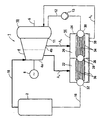
- FIG. 1 An embodiment of the invention is based on a Drawing explained in more detail.
- the figure shows schematically a steam turbine system with an axially arranged to the steam turbine Condenser and with a multiplex preheater.
- the steam turbine plant according to the figure is part of a steam power plant 1 with a steam generator 2.
- the steam turbine system comprises a steam turbine 4 with a high pressure stage 4a and a low pressure stage 4b, which has a common turbine shaft 6 drive a generator 8.
- the steam turbine 4 is designed for half-speed, i.e. the turbine shaft 6 rotates at half the network frequency of the power network to be fed.
- a condenser 10 connected downstream of the steam turbine 4, the with this is arranged in a common housing on the outflow side in the axial direction of the turbine shaft 6 and thus arranged next to the steam turbine 4.
- the condenser 10 is on the output side via a feed water line 12, in which a feed water pump 13 is connected, to a feed water preheater 14 or multiplex preheater connected.
- the feed water preheater 14 opens on the output side via a feed water line 16 into the steam generator 2, which in turn is on the output side via a live steam line 18 connected to the high pressure part 4a of the steam turbine 4 is.
- the multiplex preheater 14 comprises two heat exchanger modules 20, 22, which are arranged in a common housing 24.
- Each heat exchanger module 20, 22 of the multiplex preheater 14 is supplied with bleed steam A N or A H.
- Pressure and temperature of the bleed steam A N , A H are functions of the location of the respective bleed of the steam turbine 4.
- the bleed steam A N is taken from the low pressure stage 4b of the steam turbine 4
- the bleed steam A H is taken from the high pressure stage 4a of the steam turbine 4 is removed.
- the bleed steam A H thus has a high temperature and a high pressure, while the bleed steam A H has a comparatively low temperature and a comparatively low pressure.
- the heat exchanger modules 20, 22 arranged one behind the other are accordingly designed for the different pressure ranges of the bleed steam A H or A N.
- bleed steam A H from the high pressure stage 4a of the steam turbine 4 or also bleed steam A N from the low pressure stage 4b of the steam turbine 4 can also be supplied to both heat exchanger modules 20, 22.
- further heat exchanger modules and / or further steam taps A can be provided.
- Heat exchanger modules 20, 22 are thus parallel on the bleed steam side connected.
- the heat exchanger modules 20, 22 are over a collector 28 connected to each other.
- the collector 28 forms part of the partition 26.
- More Collectors 30, 32 are at the feedwater entry or exit of the multiplex preheater 14 is provided.
- each of the heat exchanger modules 20, 22 of feed water pipes 34 and 36 There are a number in each of the heat exchanger modules 20, 22 of feed water pipes 34 and 36 respectively.
- the feed water pipes 34 of the heat exchanger module 20 are on the input side with the inlet collector 30 and on the outlet side connected to the collector 28.
- the feed water pipes 36 of the heat exchanger module 22 on the input side with the collector 28 and connected on the output side to the outlet header 32.
- the heat exchanger modules 20, 22 of the multiplex preheater 14 are therefore connected in series on the feed water side.
- a busbar 38 common to the heat exchanger modules 20, 22 for condensed bleed steam A K is provided for returning condensed bleed steam A N , A H to the condenser 10.
- Both the steam turbine 4 with a downstream condenser 10 and the multiplex preheater 14 are at ground level and special arranged close to each other. So the space requirement particularly low for the steam turbine system.
Landscapes
- Engineering & Computer Science (AREA)
- Chemical & Material Sciences (AREA)
- Combustion & Propulsion (AREA)
- Mechanical Engineering (AREA)
- General Engineering & Computer Science (AREA)
- Engine Equipment That Uses Special Cycles (AREA)
- Organic Low-Molecular-Weight Compounds And Preparation Thereof (AREA)
- Hydrogen, Water And Hydrids (AREA)
- Turbine Rotor Nozzle Sealing (AREA)
- Commercial Cooking Devices (AREA)
Applications Claiming Priority (3)
| Application Number | Priority Date | Filing Date | Title |
|---|---|---|---|
| DE19537478A DE19537478C1 (de) | 1995-10-09 | 1995-10-09 | Dampfturbinenanlage |
| DE19537478 | 1995-10-09 | ||
| PCT/DE1996/001924 WO1997013960A2 (de) | 1995-10-09 | 1996-10-08 | Dampfturbinenanlage |
Publications (2)
| Publication Number | Publication Date |
|---|---|
| EP0854969A1 EP0854969A1 (de) | 1998-07-29 |
| EP0854969B1 true EP0854969B1 (de) | 2002-02-06 |
Family
ID=7774337
Family Applications (1)
| Application Number | Title | Priority Date | Filing Date |
|---|---|---|---|
| EP96944570A Expired - Lifetime EP0854969B1 (de) | 1995-10-09 | 1996-10-08 | Dampfturbinenanlage |
Country Status (17)
| Country | Link |
|---|---|
| US (1) | US6029454A (show.php) |
| EP (1) | EP0854969B1 (show.php) |
| JP (1) | JP2000511254A (show.php) |
| KR (1) | KR19990064124A (show.php) |
| CN (1) | CN1083526C (show.php) |
| AT (1) | ATE213052T1 (show.php) |
| AU (1) | AU700618B2 (show.php) |
| BR (1) | BR9611008A (show.php) |
| CA (1) | CA2234227A1 (show.php) |
| DE (2) | DE19537478C1 (show.php) |
| DK (1) | DK0854969T3 (show.php) |
| ES (1) | ES2172702T3 (show.php) |
| IN (1) | IN189449B (show.php) |
| PT (1) | PT854969E (show.php) |
| RU (1) | RU2169270C2 (show.php) |
| TW (1) | TW331580B (show.php) |
| WO (1) | WO1997013960A2 (show.php) |
Families Citing this family (13)
| Publication number | Priority date | Publication date | Assignee | Title |
|---|---|---|---|---|
| DE19806238C1 (de) * | 1998-02-16 | 1999-04-15 | Steag Ag | Wärmetauscheranordnung |
| DE69932989T2 (de) * | 1998-05-14 | 2007-05-10 | Yyl Corp. | Kraftwerk |
| DE59807987D1 (de) | 1998-12-11 | 2003-05-22 | Alstom Switzerland Ltd | Vorwärmer in Dampfkraftanlagen |
| AU2265301A (en) | 1999-12-17 | 2001-06-25 | Ohio State University, The | Heat engine |
| US20050000212A1 (en) * | 2001-05-15 | 2005-01-06 | Daniel Ashikian | Thermo-dynamic battery storage unit |
| EP1445429A1 (en) * | 2003-02-07 | 2004-08-11 | Elsam Engineering A/S | A steam turbine system |
| US7347057B1 (en) | 2003-12-12 | 2008-03-25 | Cooling Technologies, Inc. | Control of dual-heated absorption heat-transfer machines |
| EP1607586A1 (de) * | 2004-05-06 | 2005-12-21 | Siemens Aktiengesellschaft | Dampfkraftwerksanordnung |
| US7926555B2 (en) * | 2006-06-27 | 2011-04-19 | Gea Power Cooling, Inc. | Series-parallel condensing system |
| CN100404798C (zh) * | 2006-12-11 | 2008-07-23 | 哈尔滨汽轮机厂辅机工程有限公司 | 带内置换热器的汽轮机排汽装置 |
| WO2010132924A1 (en) * | 2009-05-18 | 2010-11-25 | Martin De Silva | System, method and components for steam power |
| US8337139B2 (en) | 2009-11-10 | 2012-12-25 | General Electric Company | Method and system for reducing the impact on the performance of a turbomachine operating an extraction system |
| JP2011214562A (ja) * | 2010-04-02 | 2011-10-27 | Mitsubishi Heavy Ind Ltd | 石炭ガス化複合発電システム |
Family Cites Families (13)
| Publication number | Priority date | Publication date | Assignee | Title |
|---|---|---|---|---|
| GB273803A (en) * | 1926-04-07 | 1927-07-07 | British Thomson Houston Co Ltd | Improvements in and relating to feed water heating systems and apparatus therefor |
| US3178891A (en) * | 1962-03-16 | 1965-04-20 | Baldwin Lima Hamilton Corp | Feedwater heater |
| GB971195A (en) * | 1962-07-23 | 1964-09-30 | Ass Elect Ind | Improvements in steam turbine power plants |
| DE2358349A1 (de) * | 1973-04-13 | 1974-10-31 | Hamon Sobelco Sa | Zweistufiger niederdruckvorwaermer |
| DE2458471C2 (de) * | 1974-12-10 | 1976-10-14 | Kraftwerk Union Ag | Speisewasservorwaermer mit zwei dampfraeumen |
| DE2553397C2 (de) * | 1975-11-27 | 1978-10-26 | Linde Ag, 6200 Wiesbaden | Röhrenwärmetauscher mit gewickeltem Rohrbündel |
| FR2583458B1 (fr) * | 1985-06-14 | 1987-08-07 | Alsthom Atlantique | Dispositif de liaison entre une turbine a vapeur et un condenseur. |
| US4870823A (en) * | 1988-11-30 | 1989-10-03 | Westinghouse Electric Corp. | Low load operation of steam turbines |
| DE3905066A1 (de) * | 1989-02-18 | 1990-08-23 | Behringwerke Ag | Waermetauschermodul |
| FR2651276B1 (fr) * | 1989-08-28 | 1991-10-25 | Alsthom Gec | Condenseur en beton pour turbine a echappement axial et turbine munie d'un tel condenseur. |
| US5404724A (en) * | 1994-04-07 | 1995-04-11 | Westinghouse Electric Corporation | Boiler feedpump turbine drive/feedwater train arrangement |
| US5457721A (en) * | 1994-05-25 | 1995-10-10 | Battelle Memorial Institute | Method and apparatus for improving the performance of a nuclear power electrical generation system |
| WO1995033127A1 (fr) * | 1994-06-01 | 1995-12-07 | Masnoi, Sergei Sergeevich | Procede d'utilisation d'une installation de turbine a vapeur et installation de turbine a vapeur destinee a la mise en oeuvre dudit procede |
-
1995
- 1995-10-09 DE DE19537478A patent/DE19537478C1/de not_active Expired - Fee Related
-
1996
- 1996-09-24 IN IN1692CA1996 patent/IN189449B/en unknown
- 1996-10-08 AT AT96944570T patent/ATE213052T1/de active
- 1996-10-08 RU RU98108601/06A patent/RU2169270C2/ru not_active IP Right Cessation
- 1996-10-08 EP EP96944570A patent/EP0854969B1/de not_active Expired - Lifetime
- 1996-10-08 PT PT96944570T patent/PT854969E/pt unknown
- 1996-10-08 JP JP09514628A patent/JP2000511254A/ja active Pending
- 1996-10-08 WO PCT/DE1996/001924 patent/WO1997013960A2/de not_active Ceased
- 1996-10-08 AU AU13007/97A patent/AU700618B2/en not_active Ceased
- 1996-10-08 CN CN96197366A patent/CN1083526C/zh not_active Expired - Fee Related
- 1996-10-08 KR KR1019980702605A patent/KR19990064124A/ko not_active Abandoned
- 1996-10-08 ES ES96944570T patent/ES2172702T3/es not_active Expired - Lifetime
- 1996-10-08 CA CA002234227A patent/CA2234227A1/en not_active Abandoned
- 1996-10-08 BR BR9611008A patent/BR9611008A/pt not_active IP Right Cessation
- 1996-10-08 DK DK96944570T patent/DK0854969T3/da active
- 1996-10-08 DE DE59608712T patent/DE59608712D1/de not_active Expired - Lifetime
- 1996-10-09 TW TW085112340A patent/TW331580B/zh active
-
1998
- 1998-04-09 US US09/057,829 patent/US6029454A/en not_active Expired - Lifetime
Also Published As
| Publication number | Publication date |
|---|---|
| IN189449B (show.php) | 2003-03-22 |
| ES2172702T3 (es) | 2002-10-01 |
| WO1997013960A3 (de) | 1997-07-10 |
| TW331580B (en) | 1998-05-11 |
| AU1300797A (en) | 1997-04-30 |
| DE59608712D1 (de) | 2002-03-21 |
| WO1997013960A2 (de) | 1997-04-17 |
| CA2234227A1 (en) | 1997-04-17 |
| ATE213052T1 (de) | 2002-02-15 |
| AU700618B2 (en) | 1999-01-07 |
| US6029454A (en) | 2000-02-29 |
| HK1013202A1 (en) | 1999-08-20 |
| DK0854969T3 (da) | 2002-05-21 |
| BR9611008A (pt) | 1999-07-13 |
| DE19537478C1 (de) | 1996-12-12 |
| EP0854969A1 (de) | 1998-07-29 |
| RU2169270C2 (ru) | 2001-06-20 |
| KR19990064124A (ko) | 1999-07-26 |
| CN1198795A (zh) | 1998-11-11 |
| JP2000511254A (ja) | 2000-08-29 |
| PT854969E (pt) | 2002-07-31 |
| CN1083526C (zh) | 2002-04-24 |
Similar Documents
| Publication | Publication Date | Title |
|---|---|---|
| EP0854969B1 (de) | Dampfturbinenanlage | |
| EP0526816B1 (de) | Gas- und Dampfturbinenkraftwerk mit einem solar beheizten Dampferzeuger | |
| EP0819209B1 (de) | Verfahren zum betreiben eines abhitzedampferzeugers sowie danach arbeitender abhitzedampferzeuger | |
| CH692629A5 (de) | Turbinenantrieb für Kesselspeisewasserpumpe. | |
| EP1111197A2 (de) | Verfahren zum Nachrüsten eines Sattdampf erzeugenden Systems mit mindestens einer Dampfturbogruppe sowie nach dem Verfahren nachgerüstete Dampfkraftanlage | |
| EP0099501A2 (de) | Verfahren zum Verändern der Abgabe von elektrischer Energie eines Heizkraftwerkes ohne Beeinflussung der Wärmeabgabe an angeschlossene Wärmeverbraucher | |
| DE3616797C2 (show.php) | ||
| WO2018010878A1 (de) | Kraftwerksanlage mit optimierter vorwärmung von speisewasser für tiefaufgestellte turbosätze | |
| DE69220240T2 (de) | Wasserdampfsystem für eine anlage mit mehreren kesseln | |
| DE19957874A1 (de) | Kombikraftwerk | |
| DE69812811T2 (de) | Verfahren und Anordnung für Kombikraftwerk | |
| EP0851971B1 (de) | Verfahren und anordnung zum vorwärmen des speisewassers eines dampferzeugers in kraftwerksprozessen | |
| DE3719861C2 (de) | Dampfturbinenanlage | |
| DE10333009B3 (de) | Anordnung zur Kondensation von Wasserdampf | |
| WO2008101830A2 (de) | Dampfturbinenanlage, kombiniertes gas- und dampfturbinenkraftwerk sowie dampfkraftwerk | |
| EP1208294A1 (de) | Verfahren und einrichtung zur erhöhung des drucks eines gases | |
| DE10111072B4 (de) | Anlage zur Erzeugung von Strom und Wärme | |
| DE19507167C1 (de) | Dampfturbinenanlage | |
| EP0657626B1 (de) | Anordnung für die Speisewassereinspeisung in einem Kombikraftwerk | |
| CH634127A5 (de) | Waermekraftwerk mit einer trockenkuehleinrichtung. | |
| EP0865596B1 (de) | Rückkühlsystem | |
| EP2026000A1 (de) | Dampferzeuger | |
| WO1997013959A2 (de) | Speisewasser-vorwärmer | |
| DE2143026A1 (de) | Kraftwerkanlage | |
| DE2634192A1 (de) | Einrichtung zum heizen von gebaeuden |
Legal Events
| Date | Code | Title | Description |
|---|---|---|---|
| PUAI | Public reference made under article 153(3) epc to a published international application that has entered the european phase |
Free format text: ORIGINAL CODE: 0009012 |
|
| 17P | Request for examination filed |
Effective date: 19980406 |
|
| AK | Designated contracting states |
Kind code of ref document: A1 Designated state(s): AT BE CH DE DK ES FR GB IE IT LI NL PT SE |
|
| GRAG | Despatch of communication of intention to grant |
Free format text: ORIGINAL CODE: EPIDOS AGRA |
|
| GRAG | Despatch of communication of intention to grant |
Free format text: ORIGINAL CODE: EPIDOS AGRA |
|
| GRAH | Despatch of communication of intention to grant a patent |
Free format text: ORIGINAL CODE: EPIDOS IGRA |
|
| 17Q | First examination report despatched |
Effective date: 20010706 |
|
| GRAH | Despatch of communication of intention to grant a patent |
Free format text: ORIGINAL CODE: EPIDOS IGRA |
|
| GRAA | (expected) grant |
Free format text: ORIGINAL CODE: 0009210 |
|
| REG | Reference to a national code |
Ref country code: GB Ref legal event code: IF02 |
|
| AK | Designated contracting states |
Kind code of ref document: B1 Designated state(s): AT BE CH DE DK ES FR GB IE IT LI NL PT SE |
|
| REF | Corresponds to: |
Ref document number: 213052 Country of ref document: AT Date of ref document: 20020215 Kind code of ref document: T |
|
| REG | Reference to a national code |
Ref country code: CH Ref legal event code: NV Representative=s name: SIEMENS SCHWEIZ AG Ref country code: CH Ref legal event code: EP |
|
| REF | Corresponds to: |
Ref document number: 59608712 Country of ref document: DE Date of ref document: 20020321 |
|
| GBT | Gb: translation of ep patent filed (gb section 77(6)(a)/1977) |
Effective date: 20020411 |
|
| REG | Reference to a national code |
Ref country code: DK Ref legal event code: T3 |
|
| ET | Fr: translation filed | ||
| REG | Reference to a national code |
Ref country code: PT Ref legal event code: SC4A Free format text: AVAILABILITY OF NATIONAL TRANSLATION Effective date: 20020415 |
|
| REG | Reference to a national code |
Ref country code: ES Ref legal event code: FG2A Ref document number: 2172702 Country of ref document: ES Kind code of ref document: T3 |
|
| PGFP | Annual fee paid to national office [announced via postgrant information from national office to epo] |
Ref country code: PT Payment date: 20021002 Year of fee payment: 7 |
|
| PGFP | Annual fee paid to national office [announced via postgrant information from national office to epo] |
Ref country code: DK Payment date: 20021014 Year of fee payment: 7 |
|
| PGFP | Annual fee paid to national office [announced via postgrant information from national office to epo] |
Ref country code: BE Payment date: 20021021 Year of fee payment: 7 |
|
| PGFP | Annual fee paid to national office [announced via postgrant information from national office to epo] |
Ref country code: IE Payment date: 20021030 Year of fee payment: 7 |
|
| PLBE | No opposition filed within time limit |
Free format text: ORIGINAL CODE: 0009261 |
|
| STAA | Information on the status of an ep patent application or granted ep patent |
Free format text: STATUS: NO OPPOSITION FILED WITHIN TIME LIMIT |
|
| 26N | No opposition filed |
Effective date: 20021107 |
|
| PG25 | Lapsed in a contracting state [announced via postgrant information from national office to epo] |
Ref country code: IE Free format text: LAPSE BECAUSE OF NON-PAYMENT OF DUE FEES Effective date: 20031008 |
|
| PG25 | Lapsed in a contracting state [announced via postgrant information from national office to epo] |
Ref country code: DK Free format text: LAPSE BECAUSE OF NON-PAYMENT OF DUE FEES Effective date: 20031031 Ref country code: BE Free format text: LAPSE BECAUSE OF NON-PAYMENT OF DUE FEES Effective date: 20031031 |
|
| BERE | Be: lapsed |
Owner name: *SIEMENS A.G. Effective date: 20031031 |
|
| PG25 | Lapsed in a contracting state [announced via postgrant information from national office to epo] |
Ref country code: PT Free format text: LAPSE BECAUSE OF NON-PAYMENT OF DUE FEES Effective date: 20040430 |
|
| REG | Reference to a national code |
Ref country code: DK Ref legal event code: EBP |
|
| REG | Reference to a national code |
Ref country code: IE Ref legal event code: MM4A |
|
| REG | Reference to a national code |
Ref country code: PT Ref legal event code: MM4A Free format text: LAPSE DUE TO NON-PAYMENT OF FEES Effective date: 20040430 |
|
| REG | Reference to a national code |
Ref country code: CH Ref legal event code: PCAR Free format text: SIEMENS SCHWEIZ AG;INTELLECTUAL PROPERTY FREILAGERSTRASSE 40;8047 ZUERICH (CH) |
|
| PGFP | Annual fee paid to national office [announced via postgrant information from national office to epo] |
Ref country code: FR Payment date: 20121031 Year of fee payment: 17 |
|
| PGFP | Annual fee paid to national office [announced via postgrant information from national office to epo] |
Ref country code: SE Payment date: 20121009 Year of fee payment: 17 Ref country code: IT Payment date: 20121030 Year of fee payment: 17 Ref country code: GB Payment date: 20121011 Year of fee payment: 17 Ref country code: ES Payment date: 20121119 Year of fee payment: 17 |
|
| PGFP | Annual fee paid to national office [announced via postgrant information from national office to epo] |
Ref country code: NL Payment date: 20121009 Year of fee payment: 17 Ref country code: AT Payment date: 20120912 Year of fee payment: 17 |
|
| PGFP | Annual fee paid to national office [announced via postgrant information from national office to epo] |
Ref country code: DE Payment date: 20121216 Year of fee payment: 17 Ref country code: CH Payment date: 20130110 Year of fee payment: 17 |
|
| REG | Reference to a national code |
Ref country code: NL Ref legal event code: V1 Effective date: 20140501 |
|
| REG | Reference to a national code |
Ref country code: CH Ref legal event code: PL |
|
| REG | Reference to a national code |
Ref country code: SE Ref legal event code: EUG |
|
| REG | Reference to a national code |
Ref country code: AT Ref legal event code: MM01 Ref document number: 213052 Country of ref document: AT Kind code of ref document: T Effective date: 20131008 |
|
| GBPC | Gb: european patent ceased through non-payment of renewal fee |
Effective date: 20131008 |
|
| PG25 | Lapsed in a contracting state [announced via postgrant information from national office to epo] |
Ref country code: LI Free format text: LAPSE BECAUSE OF NON-PAYMENT OF DUE FEES Effective date: 20131031 Ref country code: GB Free format text: LAPSE BECAUSE OF NON-PAYMENT OF DUE FEES Effective date: 20131008 Ref country code: CH Free format text: LAPSE BECAUSE OF NON-PAYMENT OF DUE FEES Effective date: 20131031 |
|
| REG | Reference to a national code |
Ref country code: FR Ref legal event code: ST Effective date: 20140630 |
|
| REG | Reference to a national code |
Ref country code: DE Ref legal event code: R119 Ref document number: 59608712 Country of ref document: DE Effective date: 20140501 |
|
| PG25 | Lapsed in a contracting state [announced via postgrant information from national office to epo] |
Ref country code: SE Free format text: LAPSE BECAUSE OF NON-PAYMENT OF DUE FEES Effective date: 20131009 Ref country code: DE Free format text: LAPSE BECAUSE OF NON-PAYMENT OF DUE FEES Effective date: 20140501 Ref country code: IT Free format text: LAPSE BECAUSE OF NON-PAYMENT OF DUE FEES Effective date: 20131008 Ref country code: NL Free format text: LAPSE BECAUSE OF NON-PAYMENT OF DUE FEES Effective date: 20140501 Ref country code: AT Free format text: LAPSE BECAUSE OF NON-PAYMENT OF DUE FEES Effective date: 20131008 Ref country code: FR Free format text: LAPSE BECAUSE OF NON-PAYMENT OF DUE FEES Effective date: 20131031 |
|
| REG | Reference to a national code |
Ref country code: ES Ref legal event code: FD2A Effective date: 20141107 |
|
| PG25 | Lapsed in a contracting state [announced via postgrant information from national office to epo] |
Ref country code: ES Free format text: LAPSE BECAUSE OF NON-PAYMENT OF DUE FEES Effective date: 20131009 |