EP0854663B1 - Assemblage anti-vol pour lampes fluorescentes - Google Patents
Assemblage anti-vol pour lampes fluorescentes Download PDFInfo
- Publication number
- EP0854663B1 EP0854663B1 EP98100229A EP98100229A EP0854663B1 EP 0854663 B1 EP0854663 B1 EP 0854663B1 EP 98100229 A EP98100229 A EP 98100229A EP 98100229 A EP98100229 A EP 98100229A EP 0854663 B1 EP0854663 B1 EP 0854663B1
- Authority
- EP
- European Patent Office
- Prior art keywords
- arm
- ring
- assembly
- leg
- connector
- Prior art date
- Legal status (The legal status is an assumption and is not a legal conclusion. Google has not performed a legal analysis and makes no representation as to the accuracy of the status listed.)
- Expired - Lifetime
Links
Images

Classifications
-
- H—ELECTRICITY
- H01—ELECTRIC ELEMENTS
- H01R—ELECTRICALLY-CONDUCTIVE CONNECTIONS; STRUCTURAL ASSOCIATIONS OF A PLURALITY OF MUTUALLY-INSULATED ELECTRICAL CONNECTING ELEMENTS; COUPLING DEVICES; CURRENT COLLECTORS
- H01R33/00—Coupling devices specially adapted for supporting apparatus and having one part acting as a holder providing support and electrical connection via a counterpart which is structurally associated with the apparatus, e.g. lamp holders; Separate parts thereof
- H01R33/97—Holders with separate means to prevent loosening of the coupling or unauthorised removal of apparatus held
- H01R33/971—Holders with separate means to prevent loosening of the coupling or unauthorised removal of apparatus held for screw type coupling devices
-
- F—MECHANICAL ENGINEERING; LIGHTING; HEATING; WEAPONS; BLASTING
- F21—LIGHTING
- F21V—FUNCTIONAL FEATURES OR DETAILS OF LIGHTING DEVICES OR SYSTEMS THEREOF; STRUCTURAL COMBINATIONS OF LIGHTING DEVICES WITH OTHER ARTICLES, NOT OTHERWISE PROVIDED FOR
- F21V19/00—Fastening of light sources or lamp holders
- F21V19/0075—Fastening of light sources or lamp holders of tubular light sources, e.g. ring-shaped fluorescent light sources
- F21V19/0095—Fastening of light sources or lamp holders of tubular light sources, e.g. ring-shaped fluorescent light sources of U-shaped tubular light sources, e.g. compact fluorescent tubes
-
- F—MECHANICAL ENGINEERING; LIGHTING; HEATING; WEAPONS; BLASTING
- F21—LIGHTING
- F21Y—INDEXING SCHEME ASSOCIATED WITH SUBCLASSES F21K, F21L, F21S and F21V, RELATING TO THE FORM OR THE KIND OF THE LIGHT SOURCES OR OF THE COLOUR OF THE LIGHT EMITTED
- F21Y2103/00—Elongate light sources, e.g. fluorescent tubes
- F21Y2103/30—Elongate light sources, e.g. fluorescent tubes curved
- F21Y2103/37—U-shaped
-
- H—ELECTRICITY
- H01—ELECTRIC ELEMENTS
- H01R—ELECTRICALLY-CONDUCTIVE CONNECTIONS; STRUCTURAL ASSOCIATIONS OF A PLURALITY OF MUTUALLY-INSULATED ELECTRICAL CONNECTING ELEMENTS; COUPLING DEVICES; CURRENT COLLECTORS
- H01R33/00—Coupling devices specially adapted for supporting apparatus and having one part acting as a holder providing support and electrical connection via a counterpart which is structurally associated with the apparatus, e.g. lamp holders; Separate parts thereof
- H01R33/05—Two-pole devices
- H01R33/06—Two-pole devices with two current-carrying pins, blades or analogous contacts, having their axes parallel to each other
- H01R33/08—Two-pole devices with two current-carrying pins, blades or analogous contacts, having their axes parallel to each other for supporting tubular fluorescent lamp
- H01R33/0809—Two-pole devices with two current-carrying pins, blades or analogous contacts, having their axes parallel to each other for supporting tubular fluorescent lamp having contacts on one side only
Definitions
- This invention relates to apparatus for deterring theft of fluorescent light bulbs, and is directed more particularly to an assembly for deterring theft of screw base compact fluorescent light bulbs from lamps in which the fluorescent bulbs are mounted in sockets for conventional incandescent light bulbs.
- Adapters typically include a starter circuit and ballast transformer.
- the U-shaped bulb that is used with the adapter usually includes, at a base portion thereof, a pair of terminal pins that plug into matching receptacles on the adapter to connect the fluorescent bulb to the ballast transformer and starter circuit.
- the adapter is threaded so that it readily can be installed in a conventional incandescent light socket, common in table lamps and floor lamps.
- an object of the invention is to provide a theft-resistant assembly for fluorescent bulb and adapter combinations.
- a further object of the invention is to provide such an assembly which affords theft deterrence without requiring placement of the ballast remote from the bulb and adapter combination, such that the only steps required to transform an incandescent lamp to a fluorescent lamp are to (1) replace the incandescent bulb with a fluorescent bulb, and (2) attach the theft-resistant assembly described herein to the bulb and adapter combination and to the lamp socket.
- a still further object of the invention is to provide such an assembly not requiring permanent attachment of the adapter to the socket, thereby permitting release of the bulb and adapter when a change of bulbs is in order.
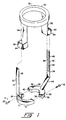
- a preferred embodiment of theft-resistant assembly for fluorescent lamps includes a first member 10, a second member 30, and a third member 50.
- the first member 10 is provided with a first semi-annular ring portion 12 and a first arm portion 14.
- the ring portion 12 is provided with first ring connectors 15 thereon such as, for example, one or the other, or both, of (1) a recess 16 and hole 18 in communication therewith (FIG 3), and (2) a threaded hole 20.
- the first ring connectors 15 further include at least one screw 22 which is insertable through the recess 16.
- the threaded hole 20 is adapted to receive a screw similar to the screw 22.
- the first arm portion 14 includes a first base portion 24 upstanding from the first ring portion 12 and may be integral with the ring portion 12, and a first locking arm portion 26 which may be integral with the first base portion 24.
- the first locking arm portion 26 is provided with a first arm connector 28, to be described hereinbelow.
- the second member 30 is provided with a second semi-annular ring portion 32 and a second arm portion 34.
- the ring portion 32 is provided with a second ring connector 35 thereon such as one or the other, or both, of (1) a recess 36 and hole 38 in communication therewith, and (2) a threaded hole 40.
- the second ring connector 35 further includes at least one screw 42 which is insertable through the recess 36.
- the threaded hole 40 is adapted to receive the screw 22 and the threaded hole 20 is adapted to receive the screw 42.
- the second arm portion 34 includes a second base portion 44 upstanding from the second ring portion 32 and may be integral with the ring portion 32, and a second locking arm portion 46 which may be integral with the second base portion 44.
- the second locking arm portion 46 is provided with a second arm connector 48, to be described hereinbelow.
- the connectors 15, 35 on the first and second ring portions 12, 32 may both be threaded holes, as at 20, 40, or may both be recesses and holes, as at 16, 18 and 36, 38.
- both screws 22, 42 may be introduced through one of the first and second ring portions 12, 32 and received by the other, to join the first and second members 10, 30 together.
- the third member 50 includes a collar portion 52, a first leg portion 54 depending from the collar portion 52, and a second leg portion 56 depending from the collar portion 52.
- the first leg portion 54 is provided with a first leg connector 58 and the second leg portion 56 similarly is provided with a second leg connector 60.
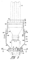
- the above-described assembly is for use with a screw base compact fluorescent lamp (shown in phantom in FIG. 2) having one or more U-tubes 70 integrated with and extending from an adapter member 72.
- the adapter member is provided with a threaded portion 74 which engages with an internally threaded socket 76 of the type generally found in incandescent lamps.
- the lamp socket 76 is provided with a protrusion 75 including a tubular portion 77 which retains, as by a set screw 79, a threaded portion 78 by which the socket 76 is mounted on a lamp base 80, as by screwing the protrusion portion 78 into a threaded hole in the lamp base 80, or by extending the protrusion portion 78 through a hole in the lamp base 80 and locking the protrusion portion 78 therein with a nut (not shown) on the inside of the lamp base 80.
- the lamp described immediately above is known in the art and is typical of incandescent lamps and typical of lamps often sought to be converted to fluorescent.
- the first and second ring portions 12, 32 are connected together by the first and second ring connectors 15, 35, such as screws 22, 42 advanced through recesses 16, 36 and holes 18, 38 and into threaded holes 20, 40 respectively, to form a complete ring 82 (FIG. 3) around the socket protrusion 75, thereby locking the ring 82 between the socket 76 and the lamp base 80.
- the collar portion 52 is then slipped over the one or more U-tubes 70 and moved toward the lamp base 80.
- FIG. 4 there is shown an enlarged elevational, partly sectional view of the second arm connector 48 which comprises second arm tooth means 84 on a surface 86 of the second arm 34.
- the tooth means 84 comprises a series of teeth 88 disposed in a line substantially axially of the socket 76, as shown in FIG. 2.
- the second leg connector 60 comprises a tooth 90 (FIG. 4) movable along the line of teeth 88 in a direction toward the lamp base 80, to move the collar 52 and ring 82 closer together.
- the tooth 90 cannot be moved in the opposite direction.
- the second leg connector 60 and the second arm connecter 48 are locked together.
- the second leg connector 60 comprises a four-sided body 94 defining a passageway 96 therethrough.
- the series of rachet-like teeth 88 is moveable through the passageway 96 in one direction only.
- the first leg connector 58 and first arm connector 28 are substantially the same in configuration and function as the second leg connector 60 and second arm connector 48.
- the locking arm portions 26, 46 which are substantially parallel to each other and to the axis of the socket 76, lock to the legs 54, 56 to lock the adapter member 72 and socket 76 therebetween.
- the four-sided bodies 94 prevent easy separation of the tooth 90 and ratchet-like teeth 88.
- teeth 88 could just as well be placed on one or more of the arms 14, 34, and the tooth 90 on one or more of the legs 54, 56.
- the application of the assembly herein is a relatively simple mechanical operation and can be performed by low-skill maintenance personnel.
- an operator unscrews the screws 22, 42 to separate the ring portions 12, 32 from each other, to permit the assembly to be lifted from the integrated bulb and adapter combination, which may then be easily removed and replaced.
- the assembly is then locked in place to deter theft of the new bulb, all in a matter of seconds.
- the assembly preferably is of molded plastic and molded in three parts, i.e., the first member 10, second member 30, and third member 50.
- the first and second members 10, 30 may be identical and therefore produced in the same mold cavity. The cost for the assembly is accordingly minimal.
Landscapes
- Engineering & Computer Science (AREA)
- General Engineering & Computer Science (AREA)
- Common Detailed Techniques For Electron Tubes Or Discharge Tubes (AREA)
- Fastening Of Light Sources Or Lamp Holders (AREA)
- Investigating Materials By The Use Of Optical Means Adapted For Particular Applications (AREA)
- Non-Portable Lighting Devices Or Systems Thereof (AREA)
Claims (12)
- Assemblage résistant au vol pour des lampes fluorescentes compactes à base vissable du type ayant au moins un tube en U d'une pièce avec un élément adaptateur et s'étendant à partir de cet élément adaptateur, l'élément adaptateur ayant une partie fileté pour une coopération avec une douille de lampe, la douille de lampe ayant une saillie par laquelle la douille de lampe est fixée à une base de lampe, l'assemblage comportant :une bague à disposer autour de la saillie de douille ;des bras s'étendant debout à partir de la bague, chacun des bras ayant un connecteur de bras sur lui ;un collet à disposer autour du tube en U et destiné à venir en coopération avec une surface supérieure de l'élément adaptateur ;des jambages qui pendent du collet, chacun des jambages ayant sur lui un connecteur de jambage ;les connecteurs de jambage pouvant coopérer avec verrouillage avec les connecteurs de bras respectivement pour verrouiller le collet à la bague, pour ainsi verrouiller l'élément adaptateur à la douille.
- Assemblage suivant la revendication 1, dans lequel la bague comporte une pluralité de segments pouvant être connectés ensemble autour de la saillie de douille, au moins deux des segments ayant chacun l'un des bras qui se tient debout à partir de lui.
- Assemblage suivant la revendication 1, dans lequel les connecteurs de bras comportent chacun des moyens formant dent de bras sur une surface de l'un des bras.
- Assemblage suivant la revendication 3, dans lequel les connecteurs de jambage comportent chacun des moyens formant dent de jambage pouvant coopérer avec verrouillage avec l'un des moyens formant dent de connecteur de bras.
- Assemblage suivant la revendication 4, dans lequel l'un des moyens formant dent de jambage et des moyens formant dent de bras comporte une série de dents disposées suivant une ligne sensiblement axialement à la douille, et l'autre des moyens formant dent de jambage et des moyens formant dent de bras comporte une dent mobile le long de la ligne des dents suivant une première direction qui déplace le collet et la bague pour les rapprocher, mais qui n'est pas mobile dans une direction opposée, pour ainsi verrouiller le collet à la bague avec une distance sélectionnée entre eux.
- Assemblage suivant la revendication 5, dans lequel l'autre des moyens formant dent comporte un corps à quatre côtés définissant un passage de traversée en son sein, et la dent est disposée dans le passage de traversée, la série de dents étant mobile dans le passage de traversée dans la première direction et en coopération avec la dent, la coopération de la dent avec ladite série de dents étant telle que l'on empêche le déplacement de la série de dents dans le passage de traversée dans la direction opposée.
- Assemblage résistant au vol pour des lampes fluorescentes compactes à base vissable du type ayant au moins un tube en U d'une pièce avec un élément adaptateur et s'étendant à partir de l'élément adaptateur, l'élément adaptateur ayant une partie filetée pour coopérer avec une douille de lampe, la douille de lampe ayant une saillie au moins en partie filetée pour coopérer avec un écrou par lequel la douille de lampe est fixée à une base de lampe, l'assemblage résistant au vol comportant :un premier élément comportant une première partie de bague semi-annulaire et une première partie de bras se tenant debout à partir de la première partie de bague, la première partie de bras ayant un premier connecteur de bras sur elle et la première partie de bague ayant sur elle un premier connecteur de bague ;un deuxième élément comportant une deuxième partie formant bague semi-annulaire et une deuxième partie de bras qui se tient debout à partir de la deuxième partie de bague, la deuxième partie de bras ayant un deuxième connecteur de bras sur elle et la deuxième partie de bague ayant un deuxième connecteur de bague sur elle ; etun troisième élément comportant une partie formant collet, une première partie de jambage pendant de la partie formant collet et ayant un premier connecteur de jambage sur elle, et une deuxième partie de jambage pendant de la partie formant collet et ayant un deuxième connecteur de jambage sur elle ;les première et deuxième parties de bague pouvant être connectées ensemble autour de la saillie de douille par coopération des premier et deuxième connecteurs de bague, la partie formant collet pouvant être disposée autour du tube en U et pouvant coopérer avec une surface supérieure de l'élément adaptateur, le premier connecteur de jambage pouvant coopérer par verrouillage avec le premier connecteur de bras, et le deuxième connecteur de jambage pouvant coopérer avec verrouillage avec le deuxième connecteur de bras, pour verrouiller le troisième élément aux premier et deuxième éléments interconnectés, pour ainsi verrouiller l'élément adaptateur à la douille.
- Assemblage suivant la revendication 7, dans lequel les premier et deuxième connecteurs de bras comportent chacun une série de dents à cliquet disposées le long d'une partie de la longueur des bras respectifs.
- Assemblage suivant la revendication 8, dans lequel au moins des parties des bras s'étendent sensiblement parallèlement à un axe longitudinal de la douille.
- Assemblage suivant la revendication 9, dans lequel les parties de bras sont généralement planes et les dents sont disposées sur des côtés des parties de bras.
- Assemblage suivant la revendication 8, dans lequel chacun des connecteurs de jambage comporte un corps proximal à une extrémité distale de la jambe respective, le corps définissant un passage de traversée en son sein pour recevoir une des parties de bras, et le connecteur de jambage comporte en outre une dent dans le corps pour coopérer avec les dents à cliquet de ladite une partie de bras et permettant un mouvement de ladite une partie de bras dans le passage de traversée dans une première direction dans laquelle la partie de collet et les parties de bague interconnectées sont tirées les unes vers les autres, et empêchant le mouvement de ladite une partie de bras par le passage de traversée dans une direction opposée.
- Assemblage suivant la revendication 11, dans lequel au moins l'une de ladite dent et desdites dents à cliquet est en matière plastique.
Applications Claiming Priority (2)
| Application Number | Priority Date | Filing Date | Title |
|---|---|---|---|
| US780907 | 1997-01-09 | ||
| US08/780,907 US5766032A (en) | 1997-01-09 | 1997-01-09 | Theft-resistant assembly for fluorescent lamps |
Publications (2)
| Publication Number | Publication Date |
|---|---|
| EP0854663A1 EP0854663A1 (fr) | 1998-07-22 |
| EP0854663B1 true EP0854663B1 (fr) | 2002-05-02 |
Family
ID=25121059
Family Applications (1)
| Application Number | Title | Priority Date | Filing Date |
|---|---|---|---|
| EP98100229A Expired - Lifetime EP0854663B1 (fr) | 1997-01-09 | 1998-01-08 | Assemblage anti-vol pour lampes fluorescentes |
Country Status (5)
| Country | Link |
|---|---|
| US (1) | US5766032A (fr) |
| EP (1) | EP0854663B1 (fr) |
| AT (1) | ATE217141T1 (fr) |
| CA (1) | CA2225767C (fr) |
| DE (1) | DE69805107T2 (fr) |
Families Citing this family (16)
| Publication number | Priority date | Publication date | Assignee | Title |
|---|---|---|---|---|
| US6612619B2 (en) * | 1999-01-05 | 2003-09-02 | Martin H. Wieder | Quick coupler retention clip and method |
| DE10010356C1 (de) * | 2000-03-07 | 2001-08-09 | Phoenix Contact Gmbh & Co | Elektrisches Gerät sowie Baueinheit aus einem elektrischen Gerät und einer Lampenwanne |
| GB0126919D0 (en) * | 2001-11-09 | 2002-01-02 | Fireangel Ltd | Anti-theft device |
| EP1576636A1 (fr) * | 2002-12-19 | 2005-09-21 | Dura Lamp S.p.A. | Lampe fluorescente avec dispositif antivol |
| US6699058B1 (en) * | 2002-12-23 | 2004-03-02 | The United States Of America As Represented By The Secretary Of The Navy | Power plug adapter assembly and method |
| US6875040B1 (en) * | 2004-01-09 | 2005-04-05 | Pirana Plugs | Lockable electric power cord adapter |
| US7402074B2 (en) * | 2004-10-22 | 2008-07-22 | Itt Manufacturing Enterprises, Inc. | Floodlight featuring dual bracket with integral strap tensioning and wire splicing |
| US7207826B1 (en) * | 2005-10-28 | 2007-04-24 | Inventec Corporation | Plug fastening device |
| GB2454883A (en) * | 2007-11-21 | 2009-05-27 | Asd Lighting Plc | A retaining device for a lamp |
| WO2009142722A2 (fr) * | 2008-05-20 | 2009-11-26 | Hirsh Donald G | Luminaires fluorescents compacts, et ensembles de conversion et adaptateurs pour lampes associés |
| EP2354825B1 (fr) * | 2010-02-03 | 2015-07-15 | Tyco Electronics Nederland B.V. | Ensemble de fermeture pour connecteur, élément de réduction de tension et procédé |
| CN202111314U (zh) * | 2011-01-14 | 2012-01-11 | 洛阳瑞光影视光电技术有限公司 | 一种锁紧装置 |
| US9461419B2 (en) * | 2013-01-31 | 2016-10-04 | Melvin G. Hector, JR. | Circuit connector with a low profile protective outlet connector arrangement cover device |
| US9433769B2 (en) * | 2013-12-11 | 2016-09-06 | Fresenius Medical Care Holdings, Inc. | Line separation protector |
| US20160161092A1 (en) * | 2014-12-04 | 2016-06-09 | Polybrite International, Inc. | Securing mechanism for a lamp bulb |
| US9647390B1 (en) * | 2016-01-29 | 2017-05-09 | Creato, Inc. | Power cord lock |
Family Cites Families (7)
| Publication number | Priority date | Publication date | Assignee | Title |
|---|---|---|---|---|
| US4637671A (en) * | 1985-10-28 | 1987-01-20 | Leviton Manufacturing Company, Inc. | Theft-resistant device for fluorescent lamp |
| US4811183A (en) * | 1988-04-18 | 1989-03-07 | Guritz Kenneth E | Tamper-resistant fluorescent tube assembly holder/adapter for lamps |
| US4936789A (en) * | 1989-08-01 | 1990-06-26 | Joseph Ugalde | Method and apparatus for preventing the theft of a fluorescent lamp and ballast transformer |
| US5065292A (en) * | 1990-05-07 | 1991-11-12 | Aubrey Truman R | Apparatus for converting a light fixture from incandescent to fluorescent |
| US5424610A (en) * | 1993-03-02 | 1995-06-13 | Lumatech Corporation | Compact fluorescent outboard ballast |
| US5404297A (en) * | 1994-01-21 | 1995-04-04 | Puritan-Bennett Corporation | Aircraft reading light |
| SE511854C2 (sv) * | 1996-01-30 | 1999-12-06 | Locklight Ab | Anordning för att förhindra obehörigt tillgrepp av en lågenergilampa |
-
1997
- 1997-01-09 US US08/780,907 patent/US5766032A/en not_active Expired - Lifetime
- 1997-12-23 CA CA002225767A patent/CA2225767C/fr not_active Expired - Fee Related
-
1998
- 1998-01-08 EP EP98100229A patent/EP0854663B1/fr not_active Expired - Lifetime
- 1998-01-08 AT AT98100229T patent/ATE217141T1/de not_active IP Right Cessation
- 1998-01-08 DE DE69805107T patent/DE69805107T2/de not_active Expired - Fee Related
Also Published As
| Publication number | Publication date |
|---|---|
| CA2225767C (fr) | 2005-07-12 |
| EP0854663A1 (fr) | 1998-07-22 |
| DE69805107T2 (de) | 2004-02-05 |
| DE69805107D1 (de) | 2002-06-06 |
| ATE217141T1 (de) | 2002-05-15 |
| US5766032A (en) | 1998-06-16 |
| CA2225767A1 (fr) | 1998-07-09 |
Similar Documents
| Publication | Publication Date | Title |
|---|---|---|
| EP0854663B1 (fr) | Assemblage anti-vol pour lampes fluorescentes | |
| US4936789A (en) | Method and apparatus for preventing the theft of a fluorescent lamp and ballast transformer | |
| US7748886B2 (en) | Incandescent and LED light bulbs and methods and devices for converting between incandescent lighting products and low-power lighting products | |
| US5759054A (en) | Locking, wire-in fluorescent light adapter | |
| US5065292A (en) | Apparatus for converting a light fixture from incandescent to fluorescent | |
| GB2384298A (en) | Plug and socket arrangement for connecting the arms and body of a chandelier | |
| EP0392578A3 (fr) | Dispositif d'installation rapide d'appareils d'éclairage pour lampadaires de rue en général | |
| US6162100A (en) | Adapter for Edison/Bayonet light sockets | |
| US5135407A (en) | Lamp conversion kit | |
| CA2557620A1 (fr) | Douille de securite pour tube fluorescent | |
| JPH09139267A (ja) | 光電制御装置のコンセント・アセンブリ及びこれに用いるコンセント | |
| CA2089444A1 (fr) | Dispositif de retenue d'ampoule | |
| CA2141337A1 (fr) | Systeme d'eclairage fluorescent | |
| US6690113B1 (en) | Fluorescent lighting assembly | |
| US6536927B1 (en) | Light fixture extension adapter | |
| CN210405972U (zh) | 易拆型pcb板固定组件 | |
| KR200228274Y1 (ko) | 형광등용 반사갓 연결대 | |
| CA2161859C (fr) | Douille de lampe | |
| CN211424154U (zh) | 一种可智能扩展的居住用照明灯 | |
| CN1351239A (zh) | 紫外线灯保持器 | |
| DE20010657U1 (de) | Arbeitsleuchte | |
| CN2489504Y (zh) | 接线盒装置 | |
| CN111895318A (zh) | 一种智能监控灯具 | |
| KR200358897Y1 (ko) | 다용도용 등기구의 전원 연결구조 | |
| WO2011064766A2 (fr) | Optimisation de tubes fluorescents à diodes électroluminescentes et à composants montés en surface |
Legal Events
| Date | Code | Title | Description |
|---|---|---|---|
| PUAI | Public reference made under article 153(3) epc to a published international application that has entered the european phase |
Free format text: ORIGINAL CODE: 0009012 |
|
| AK | Designated contracting states |
Kind code of ref document: A1 Designated state(s): AT BE CH DE DK ES FI FR GB GR IT LI NL SE |
|
| AX | Request for extension of the european patent |
Free format text: AL;LT;LV;MK;RO;SI |
|
| 17P | Request for examination filed |
Effective date: 19980819 |
|
| AKX | Designation fees paid |
Free format text: AT BE CH DE DK ES FI FR GB GR IT LI NL SE |
|
| RBV | Designated contracting states (corrected) |
Designated state(s): AT BE CH DE DK ES FI FR GB GR IT LI NL SE |
|
| GRAG | Despatch of communication of intention to grant |
Free format text: ORIGINAL CODE: EPIDOS AGRA |
|
| GRAG | Despatch of communication of intention to grant |
Free format text: ORIGINAL CODE: EPIDOS AGRA |
|
| GRAH | Despatch of communication of intention to grant a patent |
Free format text: ORIGINAL CODE: EPIDOS IGRA |
|
| 17Q | First examination report despatched |
Effective date: 20010921 |
|
| REG | Reference to a national code |
Ref country code: GB Ref legal event code: IF02 |
|
| GRAH | Despatch of communication of intention to grant a patent |
Free format text: ORIGINAL CODE: EPIDOS IGRA |
|
| GRAA | (expected) grant |
Free format text: ORIGINAL CODE: 0009210 |
|
| AK | Designated contracting states |
Kind code of ref document: B1 Designated state(s): AT BE CH DE DK ES FI FR GB GR IT LI NL SE |
|
| PG25 | Lapsed in a contracting state [announced via postgrant information from national office to epo] |
Ref country code: LI Free format text: LAPSE BECAUSE OF FAILURE TO SUBMIT A TRANSLATION OF THE DESCRIPTION OR TO PAY THE FEE WITHIN THE PRESCRIBED TIME-LIMIT Effective date: 20020502 Ref country code: GR Free format text: LAPSE BECAUSE OF FAILURE TO SUBMIT A TRANSLATION OF THE DESCRIPTION OR TO PAY THE FEE WITHIN THE PRESCRIBED TIME-LIMIT Effective date: 20020502 Ref country code: FI Free format text: LAPSE BECAUSE OF FAILURE TO SUBMIT A TRANSLATION OF THE DESCRIPTION OR TO PAY THE FEE WITHIN THE PRESCRIBED TIME-LIMIT Effective date: 20020502 Ref country code: CH Free format text: LAPSE BECAUSE OF FAILURE TO SUBMIT A TRANSLATION OF THE DESCRIPTION OR TO PAY THE FEE WITHIN THE PRESCRIBED TIME-LIMIT Effective date: 20020502 Ref country code: AT Free format text: LAPSE BECAUSE OF FAILURE TO SUBMIT A TRANSLATION OF THE DESCRIPTION OR TO PAY THE FEE WITHIN THE PRESCRIBED TIME-LIMIT Effective date: 20020502 |
|
| REF | Corresponds to: |
Ref document number: 217141 Country of ref document: AT Date of ref document: 20020515 Kind code of ref document: T |
|
| REG | Reference to a national code |
Ref country code: GB Ref legal event code: FG4D |
|
| REG | Reference to a national code |
Ref country code: CH Ref legal event code: EP |
|
| REF | Corresponds to: |
Ref document number: 69805107 Country of ref document: DE Date of ref document: 20020606 |
|
| PG25 | Lapsed in a contracting state [announced via postgrant information from national office to epo] |
Ref country code: SE Free format text: LAPSE BECAUSE OF FAILURE TO SUBMIT A TRANSLATION OF THE DESCRIPTION OR TO PAY THE FEE WITHIN THE PRESCRIBED TIME-LIMIT Effective date: 20020802 Ref country code: DK Free format text: LAPSE BECAUSE OF FAILURE TO SUBMIT A TRANSLATION OF THE DESCRIPTION OR TO PAY THE FEE WITHIN THE PRESCRIBED TIME-LIMIT Effective date: 20020802 |
|
| ET | Fr: translation filed | ||
| REG | Reference to a national code |
Ref country code: CH Ref legal event code: PL |
|
| PG25 | Lapsed in a contracting state [announced via postgrant information from national office to epo] |
Ref country code: ES Free format text: LAPSE BECAUSE OF FAILURE TO SUBMIT A TRANSLATION OF THE DESCRIPTION OR TO PAY THE FEE WITHIN THE PRESCRIBED TIME-LIMIT Effective date: 20021128 |
|
| PGFP | Annual fee paid to national office [announced via postgrant information from national office to epo] |
Ref country code: GB Payment date: 20030114 Year of fee payment: 6 |
|
| PGFP | Annual fee paid to national office [announced via postgrant information from national office to epo] |
Ref country code: NL Payment date: 20030120 Year of fee payment: 6 |
|
| PGFP | Annual fee paid to national office [announced via postgrant information from national office to epo] |
Ref country code: FR Payment date: 20030124 Year of fee payment: 6 |
|
| PGFP | Annual fee paid to national office [announced via postgrant information from national office to epo] |
Ref country code: BE Payment date: 20030128 Year of fee payment: 6 |
|
| PLBE | No opposition filed within time limit |
Free format text: ORIGINAL CODE: 0009261 |
|
| STAA | Information on the status of an ep patent application or granted ep patent |
Free format text: STATUS: NO OPPOSITION FILED WITHIN TIME LIMIT |
|
| 26N | No opposition filed |
Effective date: 20030204 |
|
| PG25 | Lapsed in a contracting state [announced via postgrant information from national office to epo] |
Ref country code: GB Free format text: LAPSE BECAUSE OF NON-PAYMENT OF DUE FEES Effective date: 20040108 |
|
| PG25 | Lapsed in a contracting state [announced via postgrant information from national office to epo] |
Ref country code: BE Free format text: LAPSE BECAUSE OF NON-PAYMENT OF DUE FEES Effective date: 20040131 |
|
| BERE | Be: lapsed |
Owner name: *OSRAM SYLVANIA INC. Effective date: 20040131 |
|
| PG25 | Lapsed in a contracting state [announced via postgrant information from national office to epo] |
Ref country code: NL Free format text: LAPSE BECAUSE OF NON-PAYMENT OF DUE FEES Effective date: 20040801 |
|
| GBPC | Gb: european patent ceased through non-payment of renewal fee |
Effective date: 20040108 |
|
| PG25 | Lapsed in a contracting state [announced via postgrant information from national office to epo] |
Ref country code: FR Free format text: LAPSE BECAUSE OF NON-PAYMENT OF DUE FEES Effective date: 20040930 |
|
| NLV4 | Nl: lapsed or anulled due to non-payment of the annual fee |
Effective date: 20040801 |
|
| REG | Reference to a national code |
Ref country code: FR Ref legal event code: ST |
|
| PG25 | Lapsed in a contracting state [announced via postgrant information from national office to epo] |
Ref country code: IT Free format text: LAPSE BECAUSE OF NON-PAYMENT OF DUE FEES;WARNING: LAPSES OF ITALIAN PATENTS WITH EFFECTIVE DATE BEFORE 2007 MAY HAVE OCCURRED AT ANY TIME BEFORE 2007. THE CORRECT EFFECTIVE DATE MAY BE DIFFERENT FROM THE ONE RECORDED. Effective date: 20050108 |
|
| PGFP | Annual fee paid to national office [announced via postgrant information from national office to epo] |
Ref country code: DE Payment date: 20060322 Year of fee payment: 9 |
|
| PG25 | Lapsed in a contracting state [announced via postgrant information from national office to epo] |
Ref country code: DE Free format text: LAPSE BECAUSE OF NON-PAYMENT OF DUE FEES Effective date: 20070801 |