EP0854663B1 - Theft-resistant assembly for fluorescent lamps - Google Patents
Theft-resistant assembly for fluorescent lamps Download PDFInfo
- Publication number
- EP0854663B1 EP0854663B1 EP98100229A EP98100229A EP0854663B1 EP 0854663 B1 EP0854663 B1 EP 0854663B1 EP 98100229 A EP98100229 A EP 98100229A EP 98100229 A EP98100229 A EP 98100229A EP 0854663 B1 EP0854663 B1 EP 0854663B1
- Authority
- EP
- European Patent Office
- Prior art keywords
- arm
- ring
- assembly
- leg
- connector
- Prior art date
- Legal status (The legal status is an assumption and is not a legal conclusion. Google has not performed a legal analysis and makes no representation as to the accuracy of the status listed.)
- Expired - Lifetime
Links
Images

Classifications
-
- H—ELECTRICITY
- H01—ELECTRIC ELEMENTS
- H01R—ELECTRICALLY-CONDUCTIVE CONNECTIONS; STRUCTURAL ASSOCIATIONS OF A PLURALITY OF MUTUALLY-INSULATED ELECTRICAL CONNECTING ELEMENTS; COUPLING DEVICES; CURRENT COLLECTORS
- H01R33/00—Coupling devices specially adapted for supporting apparatus and having one part acting as a holder providing support and electrical connection via a counterpart which is structurally associated with the apparatus, e.g. lamp holders; Separate parts thereof
- H01R33/97—Holders with separate means to prevent loosening of the coupling or unauthorised removal of apparatus held
- H01R33/971—Holders with separate means to prevent loosening of the coupling or unauthorised removal of apparatus held for screw type coupling devices
-
- F—MECHANICAL ENGINEERING; LIGHTING; HEATING; WEAPONS; BLASTING
- F21—LIGHTING
- F21V—FUNCTIONAL FEATURES OR DETAILS OF LIGHTING DEVICES OR SYSTEMS THEREOF; STRUCTURAL COMBINATIONS OF LIGHTING DEVICES WITH OTHER ARTICLES, NOT OTHERWISE PROVIDED FOR
- F21V19/00—Fastening of light sources or lamp holders
- F21V19/0075—Fastening of light sources or lamp holders of tubular light sources, e.g. ring-shaped fluorescent light sources
- F21V19/0095—Fastening of light sources or lamp holders of tubular light sources, e.g. ring-shaped fluorescent light sources of U-shaped tubular light sources, e.g. compact fluorescent tubes
-
- F—MECHANICAL ENGINEERING; LIGHTING; HEATING; WEAPONS; BLASTING
- F21—LIGHTING
- F21Y—INDEXING SCHEME ASSOCIATED WITH SUBCLASSES F21K, F21L, F21S and F21V, RELATING TO THE FORM OR THE KIND OF THE LIGHT SOURCES OR OF THE COLOUR OF THE LIGHT EMITTED
- F21Y2103/00—Elongate light sources, e.g. fluorescent tubes
- F21Y2103/30—Elongate light sources, e.g. fluorescent tubes curved
- F21Y2103/37—U-shaped
-
- H—ELECTRICITY
- H01—ELECTRIC ELEMENTS
- H01R—ELECTRICALLY-CONDUCTIVE CONNECTIONS; STRUCTURAL ASSOCIATIONS OF A PLURALITY OF MUTUALLY-INSULATED ELECTRICAL CONNECTING ELEMENTS; COUPLING DEVICES; CURRENT COLLECTORS
- H01R33/00—Coupling devices specially adapted for supporting apparatus and having one part acting as a holder providing support and electrical connection via a counterpart which is structurally associated with the apparatus, e.g. lamp holders; Separate parts thereof
- H01R33/05—Two-pole devices
- H01R33/06—Two-pole devices with two current-carrying pins, blades or analogous contacts, having their axes parallel to each other
- H01R33/08—Two-pole devices with two current-carrying pins, blades or analogous contacts, having their axes parallel to each other for supporting tubular fluorescent lamp
- H01R33/0809—Two-pole devices with two current-carrying pins, blades or analogous contacts, having their axes parallel to each other for supporting tubular fluorescent lamp having contacts on one side only
Definitions
- This invention relates to apparatus for deterring theft of fluorescent light bulbs, and is directed more particularly to an assembly for deterring theft of screw base compact fluorescent light bulbs from lamps in which the fluorescent bulbs are mounted in sockets for conventional incandescent light bulbs.
- Adapters typically include a starter circuit and ballast transformer.
- the U-shaped bulb that is used with the adapter usually includes, at a base portion thereof, a pair of terminal pins that plug into matching receptacles on the adapter to connect the fluorescent bulb to the ballast transformer and starter circuit.
- the adapter is threaded so that it readily can be installed in a conventional incandescent light socket, common in table lamps and floor lamps.
- an object of the invention is to provide a theft-resistant assembly for fluorescent bulb and adapter combinations.
- a further object of the invention is to provide such an assembly which affords theft deterrence without requiring placement of the ballast remote from the bulb and adapter combination, such that the only steps required to transform an incandescent lamp to a fluorescent lamp are to (1) replace the incandescent bulb with a fluorescent bulb, and (2) attach the theft-resistant assembly described herein to the bulb and adapter combination and to the lamp socket.
- a still further object of the invention is to provide such an assembly not requiring permanent attachment of the adapter to the socket, thereby permitting release of the bulb and adapter when a change of bulbs is in order.
- a preferred embodiment of theft-resistant assembly for fluorescent lamps includes a first member 10, a second member 30, and a third member 50.
- the first member 10 is provided with a first semi-annular ring portion 12 and a first arm portion 14.
- the ring portion 12 is provided with first ring connectors 15 thereon such as, for example, one or the other, or both, of (1) a recess 16 and hole 18 in communication therewith (FIG 3), and (2) a threaded hole 20.
- the first ring connectors 15 further include at least one screw 22 which is insertable through the recess 16.
- the threaded hole 20 is adapted to receive a screw similar to the screw 22.
- the first arm portion 14 includes a first base portion 24 upstanding from the first ring portion 12 and may be integral with the ring portion 12, and a first locking arm portion 26 which may be integral with the first base portion 24.
- the first locking arm portion 26 is provided with a first arm connector 28, to be described hereinbelow.
- the second member 30 is provided with a second semi-annular ring portion 32 and a second arm portion 34.
- the ring portion 32 is provided with a second ring connector 35 thereon such as one or the other, or both, of (1) a recess 36 and hole 38 in communication therewith, and (2) a threaded hole 40.
- the second ring connector 35 further includes at least one screw 42 which is insertable through the recess 36.
- the threaded hole 40 is adapted to receive the screw 22 and the threaded hole 20 is adapted to receive the screw 42.
- the second arm portion 34 includes a second base portion 44 upstanding from the second ring portion 32 and may be integral with the ring portion 32, and a second locking arm portion 46 which may be integral with the second base portion 44.
- the second locking arm portion 46 is provided with a second arm connector 48, to be described hereinbelow.
- the connectors 15, 35 on the first and second ring portions 12, 32 may both be threaded holes, as at 20, 40, or may both be recesses and holes, as at 16, 18 and 36, 38.
- both screws 22, 42 may be introduced through one of the first and second ring portions 12, 32 and received by the other, to join the first and second members 10, 30 together.
- the third member 50 includes a collar portion 52, a first leg portion 54 depending from the collar portion 52, and a second leg portion 56 depending from the collar portion 52.
- the first leg portion 54 is provided with a first leg connector 58 and the second leg portion 56 similarly is provided with a second leg connector 60.
- the above-described assembly is for use with a screw base compact fluorescent lamp (shown in phantom in FIG. 2) having one or more U-tubes 70 integrated with and extending from an adapter member 72.
- the adapter member is provided with a threaded portion 74 which engages with an internally threaded socket 76 of the type generally found in incandescent lamps.
- the lamp socket 76 is provided with a protrusion 75 including a tubular portion 77 which retains, as by a set screw 79, a threaded portion 78 by which the socket 76 is mounted on a lamp base 80, as by screwing the protrusion portion 78 into a threaded hole in the lamp base 80, or by extending the protrusion portion 78 through a hole in the lamp base 80 and locking the protrusion portion 78 therein with a nut (not shown) on the inside of the lamp base 80.
- the lamp described immediately above is known in the art and is typical of incandescent lamps and typical of lamps often sought to be converted to fluorescent.
- the first and second ring portions 12, 32 are connected together by the first and second ring connectors 15, 35, such as screws 22, 42 advanced through recesses 16, 36 and holes 18, 38 and into threaded holes 20, 40 respectively, to form a complete ring 82 (FIG. 3) around the socket protrusion 75, thereby locking the ring 82 between the socket 76 and the lamp base 80.
- the collar portion 52 is then slipped over the one or more U-tubes 70 and moved toward the lamp base 80.
- FIG. 4 there is shown an enlarged elevational, partly sectional view of the second arm connector 48 which comprises second arm tooth means 84 on a surface 86 of the second arm 34.
- the tooth means 84 comprises a series of teeth 88 disposed in a line substantially axially of the socket 76, as shown in FIG. 2.
- the second leg connector 60 comprises a tooth 90 (FIG. 4) movable along the line of teeth 88 in a direction toward the lamp base 80, to move the collar 52 and ring 82 closer together.
- the tooth 90 cannot be moved in the opposite direction.
- the second leg connector 60 and the second arm connecter 48 are locked together.
- the second leg connector 60 comprises a four-sided body 94 defining a passageway 96 therethrough.
- the series of rachet-like teeth 88 is moveable through the passageway 96 in one direction only.
- the first leg connector 58 and first arm connector 28 are substantially the same in configuration and function as the second leg connector 60 and second arm connector 48.
- the locking arm portions 26, 46 which are substantially parallel to each other and to the axis of the socket 76, lock to the legs 54, 56 to lock the adapter member 72 and socket 76 therebetween.
- the four-sided bodies 94 prevent easy separation of the tooth 90 and ratchet-like teeth 88.
- teeth 88 could just as well be placed on one or more of the arms 14, 34, and the tooth 90 on one or more of the legs 54, 56.
- the application of the assembly herein is a relatively simple mechanical operation and can be performed by low-skill maintenance personnel.
- an operator unscrews the screws 22, 42 to separate the ring portions 12, 32 from each other, to permit the assembly to be lifted from the integrated bulb and adapter combination, which may then be easily removed and replaced.
- the assembly is then locked in place to deter theft of the new bulb, all in a matter of seconds.
- the assembly preferably is of molded plastic and molded in three parts, i.e., the first member 10, second member 30, and third member 50.
- the first and second members 10, 30 may be identical and therefore produced in the same mold cavity. The cost for the assembly is accordingly minimal.
Abstract
Description
- This invention relates to apparatus for deterring theft of fluorescent light bulbs, and is directed more particularly to an assembly for deterring theft of screw base compact fluorescent light bulbs from lamps in which the fluorescent bulbs are mounted in sockets for conventional incandescent light bulbs.
- The advantages of fluorescent bulbs over incandescent bulbs of equivalent light intensity are well known. Though initially more expensive, the additional cost is more than offset by reduced energy consumption and extended operating life.
- To benefit from the advantages of fluorescent lighting, adapters have been developed which facilitate replacing conventional incandescent light bulbs with compact U-shaped fluorescent bulbs. Adapters typically include a starter circuit and ballast transformer. The U-shaped bulb that is used with the adapter usually includes, at a base portion thereof, a pair of terminal pins that plug into matching receptacles on the adapter to connect the fluorescent bulb to the ballast transformer and starter circuit. The adapter is threaded so that it readily can be installed in a conventional incandescent light socket, common in table lamps and floor lamps.
- It is known to provide interlocking means in adapters for securing the U-tube in the adapter, for preventing easy removal of the U-tube from the adapter. Such means are shown and described in U.S. Patent No. 4,637,671, issued January 20, 1989, to George E. Johnson, et al; and U.S. Patent No. 4,811,183, issued March 7, 1989, to Kenneth E. Guritz, et al. In typical incandescent lamps, it is easy to remove the incandescent bulb from the socket, by simply unscrewing the bulb from the socket. Similarly, while the U-tube of a fluorescent bulb may be locked into an adapter, the adapter itself can be readily unscrewed from the socket and removed.
- Attempts have been made to render such pilferage useless, or physically difficult. In U.S. Patent No. 5,065,292, issued November 12, 1991, to Truman R. Aubrey, there is disclosed an assembly for converting an incandescent table lamp to a fluorescent table lamp, which assembly includes a ballast remote from the bulb and adapted for locking engagement with a wall outlet receptacle. Aubrey further suggests applying glue to the adapter screw threads prior to screwing the adapter into the lamp socket. Accordingly, removal of the adapter and bulb is discouraged by the glue, but even if removed is lacking the ballast necessary for operation.
- In U.S. Patent No. 4,936,789, issued June 26, 1990, to Joseph Ugalde, there is presented means for preventing removal of an adapter from a socket. The adapter threaded portion is provided with an inset annular split ring which serves to lock the adapter threaded portion into the lamp socket. After installation, the adapter cannot be unscrewed from the socket.
- In U.S. Patent No. 5,424,610, issued June 13, 1995, to Bruce A. Pelton, et al, there is shown means for locking a harp (lamp shade support) onto a fixture to prevent removal of the harp, to render difficult removal of the adapter and bulb.
- The long-term benefits of fluorescent bulbs, as opposed to incandescent bulbs, are attractive to hotel and motel operators, but theft of the fluorescent bulbs, of course, counteracts the otherwise expected savings and discourages large-scale use of the fluorescent bulbs.
- Use of permanent bonds between adapters and sockets is not favored inasmuch as it is preferable to simply unscrew and discard used-up bulbs and adapters and replace them by screwing in new bulb and adapter assemblies. In short, it is desired to make bulb removal easy for hotel and motel maintenance people, but difficult for pilferers. Further, it is desirable to retain the ballast in the adapter so that lamps may be used interchangeably for incandescent or fluorescent bulbs. Still further, in view of the high initial costs of the fluorescent assemblies, it is essential that any theft deterrent means added thereto be of extremely low cost.
- In view thereof, an object of the invention is to provide a theft-resistant assembly for fluorescent bulb and adapter combinations.
- A further object of the invention is to provide such an assembly which affords theft deterrence without requiring placement of the ballast remote from the bulb and adapter combination, such that the only steps required to transform an incandescent lamp to a fluorescent lamp are to (1) replace the incandescent bulb with a fluorescent bulb, and (2) attach the theft-resistant assembly described herein to the bulb and adapter combination and to the lamp socket.
- A still further object of the invention is to provide such an assembly not requiring permanent attachment of the adapter to the socket, thereby permitting release of the bulb and adapter when a change of bulbs is in order.
- A still further object of the invention is to provide such an assembly which is of extremely low cost and can be installed by maintenance people having little or no knowledge of electricity, but which deters theft by pilferers.
- With the above and other objects in view, as will hereinafter appear, a feature of the present invention is the provision of a theft-resistant assembly for fluorescent lamps of the type having at least one U-tube integrated with and extending from an adapter member, the adapter member having a threaded portion for engagement with a lamp socket, and the lamp socket having a protrusion by which the lamp socket is secured to a lamp base. The assembly comprises a ring for disposition around the socket protrusion, arms upstanding from the ring, each of the arms having an arm connector thereon, a collar for disposition around the U-tube and for engagement with a top surface of the adapter member, and arms depending from the collar, each of the arms having an arm connector thereon. The arm connectors are lockingly engageable with the leg connectors, respectively, to lock the collar to the ring, whereby to lock the adapter member to the socket.
- The above and other features of the invention, including various novel details of construction and combinations of parts, will now be more particularly described with reference to the accompanying drawings and pointed out in the claims. It will be understood that the particular device embodying the invention is shown by way of illustration only and not as a limitation of the invention. The principles and features of this invention may be employed in various and numerous embodiments without departing from the scope of the invention.
- Reference is made to the accompanying drawings in which is shown an illustrative embodiment of the invention, from which its novel features and advantages will be apparent.
- In the drawings:
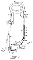
- FIG. 1 is a perspective exploded view of one form of theft-resistant assembly illustrative of an embodiment of the invention;
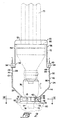
- FIG. 2 is a side elevational view of the components of FIG. 1 assembled together and in place on a table lamp;
- FIG. 3 is a sectional view taken along line III-III of FIG. 2; and
- FIG. 4 is an enlarged side elevation, partly sectional, view of components of the assembly of FIG. 2.
-
- Referring to FIG. 1, it will be seen that a preferred embodiment of theft-resistant assembly for fluorescent lamps includes a
first member 10, asecond member 30, and athird member 50. - The
first member 10 is provided with a firstsemi-annular ring portion 12 and afirst arm portion 14. Thering portion 12 is provided withfirst ring connectors 15 thereon such as, for example, one or the other, or both, of (1) arecess 16 andhole 18 in communication therewith (FIG 3), and (2) a threaded hole 20. Thefirst ring connectors 15 further include at least onescrew 22 which is insertable through therecess 16. The threaded hole 20 is adapted to receive a screw similar to thescrew 22. Thefirst arm portion 14 includes afirst base portion 24 upstanding from thefirst ring portion 12 and may be integral with thering portion 12, and a firstlocking arm portion 26 which may be integral with thefirst base portion 24. The firstlocking arm portion 26 is provided with afirst arm connector 28, to be described hereinbelow. - Similarly, the
second member 30 is provided with a secondsemi-annular ring portion 32 and asecond arm portion 34. Thering portion 32 is provided with asecond ring connector 35 thereon such as one or the other, or both, of (1) arecess 36 andhole 38 in communication therewith, and (2) a threadedhole 40. Thesecond ring connector 35 further includes at least onescrew 42 which is insertable through therecess 36. The threadedhole 40 is adapted to receive thescrew 22 and the threaded hole 20 is adapted to receive thescrew 42. Thesecond arm portion 34 includes asecond base portion 44 upstanding from thesecond ring portion 32 and may be integral with thering portion 32, and a secondlocking arm portion 46 which may be integral with thesecond base portion 44. The secondlocking arm portion 46 is provided with asecond arm connector 48, to be described hereinbelow. - It will be apparent that the
connectors second ring portions screws second ring portions second members - The
third member 50 includes acollar portion 52, afirst leg portion 54 depending from thecollar portion 52, and asecond leg portion 56 depending from thecollar portion 52. Thefirst leg portion 54 is provided with afirst leg connector 58 and thesecond leg portion 56 similarly is provided with asecond leg connector 60. - The above-described assembly is for use with a screw base compact fluorescent lamp (shown in phantom in FIG. 2) having one or
more U-tubes 70 integrated with and extending from anadapter member 72. The adapter member is provided with a threaded portion 74 which engages with an internally threaded socket 76 of the type generally found in incandescent lamps. The lamp socket 76 is provided with aprotrusion 75 including atubular portion 77 which retains, as by a set screw 79, a threadedportion 78 by which the socket 76 is mounted on a lamp base 80, as by screwing theprotrusion portion 78 into a threaded hole in the lamp base 80, or by extending theprotrusion portion 78 through a hole in the lamp base 80 and locking theprotrusion portion 78 therein with a nut (not shown) on the inside of the lamp base 80. The lamp described immediately above is known in the art and is typical of incandescent lamps and typical of lamps often sought to be converted to fluorescent. - In using the theft resistant assembly herein, the first and
second ring portions second ring connectors screws recesses holes 20, 40 respectively, to form a complete ring 82 (FIG. 3) around thesocket protrusion 75, thereby locking thering 82 between the socket 76 and the lamp base 80. Thecollar portion 52 is then slipped over the one or more U-tubes 70 and moved toward the lamp base 80. - Referring to FIG. 4, there is shown an enlarged elevational, partly sectional view of the
second arm connector 48 which comprises second arm tooth means 84 on asurface 86 of thesecond arm 34. The tooth means 84 comprises a series ofteeth 88 disposed in a line substantially axially of the socket 76, as shown in FIG. 2. Thesecond leg connector 60 comprises a tooth 90 (FIG. 4) movable along the line ofteeth 88 in a direction toward the lamp base 80, to move thecollar 52 andring 82 closer together. However, once thecollar 52 engages atop surface 92 of theadapter 72, thetooth 90 cannot be moved in the opposite direction. Thus, thesecond leg connector 60 and thesecond arm connecter 48 are locked together. - Referring again to FIG. 4, it will be seen that the
second leg connector 60 comprises a four-sided body 94 defining apassageway 96 therethrough. The series of rachet-like teeth 88 is moveable through thepassageway 96 in one direction only. - The
first leg connector 58 andfirst arm connector 28 are substantially the same in configuration and function as thesecond leg connector 60 andsecond arm connector 48. Thus, the lockingarm portions legs adapter member 72 and socket 76 therebetween. The four-sided bodies 94 prevent easy separation of thetooth 90 and ratchet-like teeth 88. Upon completion of the locking operation, theadapter member 72, having the U-tube 70 locked therein, is locked in place. - It will be appreciated that the
teeth 88 could just as well be placed on one or more of thearms tooth 90 on one or more of thelegs - It is recognized that diligent work on the part of a thief will, in due course, uncouple the first and second
locking arm portions third member 50. It is further recognized that thelegs arms - The application of the assembly herein is a relatively simple mechanical operation and can be performed by low-skill maintenance personnel. When the time comes to remove and replace the bulb, an operator unscrews the
screws ring portions - The assembly preferably is of molded plastic and molded in three parts, i.e., the
first member 10,second member 30, andthird member 50. The first andsecond members - There is thus provided a theft-resistant assembly for the protection of fluorescent bulbs in incandescent table lamps, and the like. The assembly is inexpensive to manufacture and easily installed, and does not require special provision for ballasts.
Claims (12)
- A theft-resistant assembly for screw base compact fluorescent lamps of the type having at least one U-tube integrated with and extending from an adapter member, the adapter member having a threaded portion for engagement with a lamp socket, the lamp socket having a protrusion by which the lamp socket is secured to a lamp base, the assembly comprising:a ring for disposition around the socket protrusion;arms upstanding from said ring, each of said arms having an arm connector thereon;a collar for disposition around the U-tube and for engagement with a top surface of the adapter member;legs depending from said collar, each of said legs having a leg connector thereon;said leg connectors being lockingly engageable with said arm connectors, respectively, to lock said collar to said ring, whereby to lock the adapter member to the socket.
- The assembly in accordance with claim 1 wherein said ring includes a plurality of segments connectable together around the socket protrusion, at least two of said segments each having one of said arms upstanding therefrom.
- The assembly in accordance with claim 1 wherein said arm connectors each comprises arm tooth means on a surface of one of said arms.
- The assembly in accordance with claim 3 wherein said leg connectors each comprises leg tooth means lockingly engageable with one of said arm connector tooth means.
- The assembly in accordance with claim 4 wherein one of said leg tooth means and said arm tooth means comprises a series of teeth disposed in a line substantially axially of the socket, and the other of said leg tooth means and said arm tooth means comprises a tooth movable along said line of teeth in a first direction moving said collar and said ring closer together, but not movable in an opposite direction, whereby to lock said collar to said ring with a selected distance therebetween.
- The assembly in accordance with claim 5 wherein said other of said tooth means comprises a four-sided body defining a passageway therethrough, and said tooth is disposed in said passageway, said series of teeth being movable through said passageway in said first direction and in engagement with said tooth, said engagement of said tooth with said series of teeth being such as to prevent movement of said series of teeth in said passageway in said opposite direction.
- A theft-resistant assembly for screw base compact fluorescent lamps of the type having at least one U-tube integrated with and extending from an adapter member, the adapter member having a threaded portion for engagement with a lamp socket, the lamp socket having a protrusion at least in part threaded for engagement with a nut by which the lamp socket is secured to a lamp base, the theft-resistant assembly comprising:a first member comprising a first semi-annular ring portion and a first arm portion upstanding from said first ring portion, said first arm portion having a first arm connector thereon and said first ring portion having a first ring connector thereon;a second member comprising a second semi-annular ring portion and a second arm portion upstanding from said second ring portion, said second arm portion having a second arm connector thereon and said second ring portion having a second ring connector thereon; anda third member comprising a collar portion, a first leg portion depending from said collar portion and having a first leg connector thereon, and a second leg portion depending from said collar portion and having a second leg connector thereon;said first and second ring portions being connectable together around the socket protrusion by engagement of said first and second ring connectors, said collar portion being disposable around the U-tube and engageable with a top surface of the adapter member, said first leg connector being lockingly engageable with said first arm connector, and said second leg connector being lockingly engageable with said second arm connector, to lock said third member to said interconnected first and second members, whereby to lock the adapter member to the socket.
- The assembly in accordance with claim 7 wherein said first and second arm connectors each comprises a series of ratchet teeth disposed along a portion of the length of the respective arms.
- The assembly in accordance with claim 8 wherein at least portions of said arms extend substantially parallel to a longitudinal axis of the socket.
- The assembly in accordance with claim 9 wherein said arm portions are generally planar and said teeth are disposed on sides of said arm portions.
- The assembly in accordance with claim 8 wherein each of said leg connectors comprises a body proximate a distal end of the respective leg, said body defining a passageway therethrough for receiving one of said arm portions, and said leg connector further comprises a tooth in said body for engaging said ratchet teeth of said one arm portion and permitting movement of said one arm portion through said passageway in a first direction in which said collar portion and said interconnected ring portions are drawn toward one another, and preventing movement of said one arm portion through said passageway in an opposite direction.
- The assembly in accordance with claim 11 wherein at least one of said tooth and said ratchet teeth is of a plastic material.
Applications Claiming Priority (2)
| Application Number | Priority Date | Filing Date | Title |
|---|---|---|---|
| US08/780,907 US5766032A (en) | 1997-01-09 | 1997-01-09 | Theft-resistant assembly for fluorescent lamps |
| US780907 | 1997-01-09 |
Publications (2)
| Publication Number | Publication Date |
|---|---|
| EP0854663A1 EP0854663A1 (en) | 1998-07-22 |
| EP0854663B1 true EP0854663B1 (en) | 2002-05-02 |
Family
ID=25121059
Family Applications (1)
| Application Number | Title | Priority Date | Filing Date |
|---|---|---|---|
| EP98100229A Expired - Lifetime EP0854663B1 (en) | 1997-01-09 | 1998-01-08 | Theft-resistant assembly for fluorescent lamps |
Country Status (5)
| Country | Link |
|---|---|
| US (1) | US5766032A (en) |
| EP (1) | EP0854663B1 (en) |
| AT (1) | ATE217141T1 (en) |
| CA (1) | CA2225767C (en) |
| DE (1) | DE69805107T2 (en) |
Families Citing this family (16)
| Publication number | Priority date | Publication date | Assignee | Title |
|---|---|---|---|---|
| US6612619B2 (en) * | 1999-01-05 | 2003-09-02 | Martin H. Wieder | Quick coupler retention clip and method |
| DE10010356C1 (en) * | 2000-03-07 | 2001-08-09 | Phoenix Contact Gmbh & Co | Electrical device and assembly from an electrical device and a lamp tray |
| GB0126919D0 (en) * | 2001-11-09 | 2002-01-02 | Fireangel Ltd | Anti-theft device |
| WO2004057639A1 (en) * | 2002-12-19 | 2004-07-08 | Dura Lamp S.P.A. | Fluorescent lamp with antitheft device |
| US6699058B1 (en) * | 2002-12-23 | 2004-03-02 | The United States Of America As Represented By The Secretary Of The Navy | Power plug adapter assembly and method |
| US6875040B1 (en) * | 2004-01-09 | 2005-04-05 | Pirana Plugs | Lockable electric power cord adapter |
| US7402074B2 (en) * | 2004-10-22 | 2008-07-22 | Itt Manufacturing Enterprises, Inc. | Floodlight featuring dual bracket with integral strap tensioning and wire splicing |
| US7207826B1 (en) * | 2005-10-28 | 2007-04-24 | Inventec Corporation | Plug fastening device |
| GB2454883A (en) * | 2007-11-21 | 2009-05-27 | Asd Lighting Plc | A retaining device for a lamp |
| WO2009142722A2 (en) * | 2008-05-20 | 2009-11-26 | Hirsh Donald G | Compact fluorescent light fixtures and related lamp conversion kits and adapters |
| EP2927720B1 (en) * | 2010-02-03 | 2018-10-17 | Tyco Electronics Nederland B.V. | Enclosure assembly for a connector, strain relief element, and method |
| CN202111314U (en) * | 2011-01-14 | 2012-01-11 | 洛阳瑞光影视光电技术有限公司 | Locking device |
| US9461419B2 (en) * | 2013-01-31 | 2016-10-04 | Melvin G. Hector, JR. | Circuit connector with a low profile protective outlet connector arrangement cover device |
| US9433769B2 (en) * | 2013-12-11 | 2016-09-06 | Fresenius Medical Care Holdings, Inc. | Line separation protector |
| US20160161092A1 (en) * | 2014-12-04 | 2016-06-09 | Polybrite International, Inc. | Securing mechanism for a lamp bulb |
| US9647390B1 (en) * | 2016-01-29 | 2017-05-09 | Creato, Inc. | Power cord lock |
Family Cites Families (7)
| Publication number | Priority date | Publication date | Assignee | Title |
|---|---|---|---|---|
| US4637671A (en) * | 1985-10-28 | 1987-01-20 | Leviton Manufacturing Company, Inc. | Theft-resistant device for fluorescent lamp |
| US4811183A (en) * | 1988-04-18 | 1989-03-07 | Guritz Kenneth E | Tamper-resistant fluorescent tube assembly holder/adapter for lamps |
| US4936789A (en) * | 1989-08-01 | 1990-06-26 | Joseph Ugalde | Method and apparatus for preventing the theft of a fluorescent lamp and ballast transformer |
| US5065292A (en) * | 1990-05-07 | 1991-11-12 | Aubrey Truman R | Apparatus for converting a light fixture from incandescent to fluorescent |
| US5424610A (en) * | 1993-03-02 | 1995-06-13 | Lumatech Corporation | Compact fluorescent outboard ballast |
| US5404297A (en) * | 1994-01-21 | 1995-04-04 | Puritan-Bennett Corporation | Aircraft reading light |
| SE511854C2 (en) * | 1996-01-30 | 1999-12-06 | Locklight Ab | Device for preventing unauthorized use of a low-energy lamp |
-
1997
- 1997-01-09 US US08/780,907 patent/US5766032A/en not_active Expired - Lifetime
- 1997-12-23 CA CA002225767A patent/CA2225767C/en not_active Expired - Fee Related
-
1998
- 1998-01-08 DE DE69805107T patent/DE69805107T2/en not_active Expired - Fee Related
- 1998-01-08 AT AT98100229T patent/ATE217141T1/en not_active IP Right Cessation
- 1998-01-08 EP EP98100229A patent/EP0854663B1/en not_active Expired - Lifetime
Also Published As
| Publication number | Publication date |
|---|---|
| EP0854663A1 (en) | 1998-07-22 |
| ATE217141T1 (en) | 2002-05-15 |
| CA2225767C (en) | 2005-07-12 |
| DE69805107D1 (en) | 2002-06-06 |
| DE69805107T2 (en) | 2004-02-05 |
| US5766032A (en) | 1998-06-16 |
| CA2225767A1 (en) | 1998-07-09 |
Similar Documents
| Publication | Publication Date | Title |
|---|---|---|
| EP0854663B1 (en) | Theft-resistant assembly for fluorescent lamps | |
| US4936789A (en) | Method and apparatus for preventing the theft of a fluorescent lamp and ballast transformer | |
| US7748886B2 (en) | Incandescent and LED light bulbs and methods and devices for converting between incandescent lighting products and low-power lighting products | |
| US5759054A (en) | Locking, wire-in fluorescent light adapter | |
| CA2611755C (en) | Rotatable magnetic electrical connector | |
| US5065292A (en) | Apparatus for converting a light fixture from incandescent to fluorescent | |
| US5624029A (en) | Tool box with a lighting apparatus | |
| GB2384298A (en) | Plug and socket arrangement for connecting the arms and body of a chandelier | |
| US6162100A (en) | Adapter for Edison/Bayonet light sockets | |
| US5135407A (en) | Lamp conversion kit | |
| JPH09139267A (en) | Outlet assembly of photoelectric controller and outlet that is used for it | |
| CA2089444A1 (en) | Two-piece locking lamp fixture | |
| CA2141337A1 (en) | Fluorescent lighting system | |
| US6690113B1 (en) | Fluorescent lighting assembly | |
| US6536927B1 (en) | Light fixture extension adapter | |
| CN210405972U (en) | Easily-disassembled PCB fixing assembly | |
| KR200228274Y1 (en) | A Fluorescent Lighting Connection Stick | |
| CA2161859C (en) | Light bulb socket assembly | |
| CN211424154U (en) | Intelligent-expansion residential illuminating lamp | |
| DE20010657U1 (en) | Work light | |
| CN2489504Y (en) | Terminal box device | |
| CN111895318A (en) | Intelligent monitoring lamp | |
| KR200358897Y1 (en) | connection construction of sources of electricity of an apparatus a lamp | |
| WO2011064766A2 (en) | Optimization of led and smd fluorescent tubes | |
| WO2003049143A3 (en) | Adapter for protected sockets |
Legal Events
| Date | Code | Title | Description |
|---|---|---|---|
| PUAI | Public reference made under article 153(3) epc to a published international application that has entered the european phase |
Free format text: ORIGINAL CODE: 0009012 |
|
| AK | Designated contracting states |
Kind code of ref document: A1 Designated state(s): AT BE CH DE DK ES FI FR GB GR IT LI NL SE |
|
| AX | Request for extension of the european patent |
Free format text: AL;LT;LV;MK;RO;SI |
|
| 17P | Request for examination filed |
Effective date: 19980819 |
|
| AKX | Designation fees paid |
Free format text: AT BE CH DE DK ES FI FR GB GR IT LI NL SE |
|
| RBV | Designated contracting states (corrected) |
Designated state(s): AT BE CH DE DK ES FI FR GB GR IT LI NL SE |
|
| GRAG | Despatch of communication of intention to grant |
Free format text: ORIGINAL CODE: EPIDOS AGRA |
|
| GRAG | Despatch of communication of intention to grant |
Free format text: ORIGINAL CODE: EPIDOS AGRA |
|
| GRAH | Despatch of communication of intention to grant a patent |
Free format text: ORIGINAL CODE: EPIDOS IGRA |
|
| 17Q | First examination report despatched |
Effective date: 20010921 |
|
| REG | Reference to a national code |
Ref country code: GB Ref legal event code: IF02 |
|
| GRAH | Despatch of communication of intention to grant a patent |
Free format text: ORIGINAL CODE: EPIDOS IGRA |
|
| GRAA | (expected) grant |
Free format text: ORIGINAL CODE: 0009210 |
|
| AK | Designated contracting states |
Kind code of ref document: B1 Designated state(s): AT BE CH DE DK ES FI FR GB GR IT LI NL SE |
|
| PG25 | Lapsed in a contracting state [announced via postgrant information from national office to epo] |
Ref country code: LI Free format text: LAPSE BECAUSE OF FAILURE TO SUBMIT A TRANSLATION OF THE DESCRIPTION OR TO PAY THE FEE WITHIN THE PRESCRIBED TIME-LIMIT Effective date: 20020502 Ref country code: GR Free format text: LAPSE BECAUSE OF FAILURE TO SUBMIT A TRANSLATION OF THE DESCRIPTION OR TO PAY THE FEE WITHIN THE PRESCRIBED TIME-LIMIT Effective date: 20020502 Ref country code: FI Free format text: LAPSE BECAUSE OF FAILURE TO SUBMIT A TRANSLATION OF THE DESCRIPTION OR TO PAY THE FEE WITHIN THE PRESCRIBED TIME-LIMIT Effective date: 20020502 Ref country code: CH Free format text: LAPSE BECAUSE OF FAILURE TO SUBMIT A TRANSLATION OF THE DESCRIPTION OR TO PAY THE FEE WITHIN THE PRESCRIBED TIME-LIMIT Effective date: 20020502 Ref country code: AT Free format text: LAPSE BECAUSE OF FAILURE TO SUBMIT A TRANSLATION OF THE DESCRIPTION OR TO PAY THE FEE WITHIN THE PRESCRIBED TIME-LIMIT Effective date: 20020502 |
|
| REF | Corresponds to: |
Ref document number: 217141 Country of ref document: AT Date of ref document: 20020515 Kind code of ref document: T |
|
| REG | Reference to a national code |
Ref country code: GB Ref legal event code: FG4D |
|
| REG | Reference to a national code |
Ref country code: CH Ref legal event code: EP |
|
| REF | Corresponds to: |
Ref document number: 69805107 Country of ref document: DE Date of ref document: 20020606 |
|
| PG25 | Lapsed in a contracting state [announced via postgrant information from national office to epo] |
Ref country code: SE Free format text: LAPSE BECAUSE OF FAILURE TO SUBMIT A TRANSLATION OF THE DESCRIPTION OR TO PAY THE FEE WITHIN THE PRESCRIBED TIME-LIMIT Effective date: 20020802 Ref country code: DK Free format text: LAPSE BECAUSE OF FAILURE TO SUBMIT A TRANSLATION OF THE DESCRIPTION OR TO PAY THE FEE WITHIN THE PRESCRIBED TIME-LIMIT Effective date: 20020802 |
|
| ET | Fr: translation filed | ||
| REG | Reference to a national code |
Ref country code: CH Ref legal event code: PL |
|
| PG25 | Lapsed in a contracting state [announced via postgrant information from national office to epo] |
Ref country code: ES Free format text: LAPSE BECAUSE OF FAILURE TO SUBMIT A TRANSLATION OF THE DESCRIPTION OR TO PAY THE FEE WITHIN THE PRESCRIBED TIME-LIMIT Effective date: 20021128 |
|
| PGFP | Annual fee paid to national office [announced via postgrant information from national office to epo] |
Ref country code: GB Payment date: 20030114 Year of fee payment: 6 |
|
| PGFP | Annual fee paid to national office [announced via postgrant information from national office to epo] |
Ref country code: NL Payment date: 20030120 Year of fee payment: 6 |
|
| PGFP | Annual fee paid to national office [announced via postgrant information from national office to epo] |
Ref country code: FR Payment date: 20030124 Year of fee payment: 6 |
|
| PGFP | Annual fee paid to national office [announced via postgrant information from national office to epo] |
Ref country code: BE Payment date: 20030128 Year of fee payment: 6 |
|
| PLBE | No opposition filed within time limit |
Free format text: ORIGINAL CODE: 0009261 |
|
| STAA | Information on the status of an ep patent application or granted ep patent |
Free format text: STATUS: NO OPPOSITION FILED WITHIN TIME LIMIT |
|
| 26N | No opposition filed |
Effective date: 20030204 |
|
| PG25 | Lapsed in a contracting state [announced via postgrant information from national office to epo] |
Ref country code: GB Free format text: LAPSE BECAUSE OF NON-PAYMENT OF DUE FEES Effective date: 20040108 |
|
| PG25 | Lapsed in a contracting state [announced via postgrant information from national office to epo] |
Ref country code: BE Free format text: LAPSE BECAUSE OF NON-PAYMENT OF DUE FEES Effective date: 20040131 |
|
| BERE | Be: lapsed |
Owner name: *OSRAM SYLVANIA INC. Effective date: 20040131 |
|
| PG25 | Lapsed in a contracting state [announced via postgrant information from national office to epo] |
Ref country code: NL Free format text: LAPSE BECAUSE OF NON-PAYMENT OF DUE FEES Effective date: 20040801 |
|
| GBPC | Gb: european patent ceased through non-payment of renewal fee |
Effective date: 20040108 |
|
| PG25 | Lapsed in a contracting state [announced via postgrant information from national office to epo] |
Ref country code: FR Free format text: LAPSE BECAUSE OF NON-PAYMENT OF DUE FEES Effective date: 20040930 |
|
| NLV4 | Nl: lapsed or anulled due to non-payment of the annual fee |
Effective date: 20040801 |
|
| REG | Reference to a national code |
Ref country code: FR Ref legal event code: ST |
|
| PG25 | Lapsed in a contracting state [announced via postgrant information from national office to epo] |
Ref country code: IT Free format text: LAPSE BECAUSE OF NON-PAYMENT OF DUE FEES;WARNING: LAPSES OF ITALIAN PATENTS WITH EFFECTIVE DATE BEFORE 2007 MAY HAVE OCCURRED AT ANY TIME BEFORE 2007. THE CORRECT EFFECTIVE DATE MAY BE DIFFERENT FROM THE ONE RECORDED. Effective date: 20050108 |
|
| PGFP | Annual fee paid to national office [announced via postgrant information from national office to epo] |
Ref country code: DE Payment date: 20060322 Year of fee payment: 9 |
|
| PG25 | Lapsed in a contracting state [announced via postgrant information from national office to epo] |
Ref country code: DE Free format text: LAPSE BECAUSE OF NON-PAYMENT OF DUE FEES Effective date: 20070801 |