EP0854340B1 - Lager mit austauschbaren Reibbelägen für einen rotierenden Werkstück wie einen Drehrohrofen - Google Patents
Lager mit austauschbaren Reibbelägen für einen rotierenden Werkstück wie einen Drehrohrofen Download PDFInfo
- Publication number
- EP0854340B1 EP0854340B1 EP98400004A EP98400004A EP0854340B1 EP 0854340 B1 EP0854340 B1 EP 0854340B1 EP 98400004 A EP98400004 A EP 98400004A EP 98400004 A EP98400004 A EP 98400004A EP 0854340 B1 EP0854340 B1 EP 0854340B1
- Authority
- EP
- European Patent Office
- Prior art keywords
- support member
- interchangeable
- process according
- support
- rotation axis
- Prior art date
- Legal status (The legal status is an assumption and is not a legal conclusion. Google has not performed a legal analysis and makes no representation as to the accuracy of the status listed.)
- Expired - Lifetime
Links
- 238000000034 method Methods 0.000 claims description 18
- 230000008878 coupling Effects 0.000 claims description 6
- 238000010168 coupling process Methods 0.000 claims description 6
- 238000005859 coupling reaction Methods 0.000 claims description 6
- 238000006073 displacement reaction Methods 0.000 claims description 3
- 230000000149 penetrating effect Effects 0.000 claims 1
- 210000000056 organ Anatomy 0.000 description 7
- 208000031968 Cadaver Diseases 0.000 description 2
- 238000001354 calcination Methods 0.000 description 2
- 238000009434 installation Methods 0.000 description 2
- 239000002699 waste material Substances 0.000 description 2
- 241000920340 Pion Species 0.000 description 1
- 229920000297 Rayon Polymers 0.000 description 1
- 230000000295 complement effect Effects 0.000 description 1
- 239000012530 fluid Substances 0.000 description 1
- 238000010438 heat treatment Methods 0.000 description 1
- 239000000463 material Substances 0.000 description 1
- 239000002964 rayon Substances 0.000 description 1
- 230000000284 resting effect Effects 0.000 description 1
- 238000005096 rolling process Methods 0.000 description 1
Images

Classifications
-
- F—MECHANICAL ENGINEERING; LIGHTING; HEATING; WEAPONS; BLASTING
- F27—FURNACES; KILNS; OVENS; RETORTS
- F27B—FURNACES, KILNS, OVENS OR RETORTS IN GENERAL; OPEN SINTERING OR LIKE APPARATUS
- F27B7/00—Rotary-drum furnaces, i.e. horizontal or slightly inclined
- F27B7/20—Details, accessories or equipment specially adapted for rotary-drum furnaces
- F27B7/22—Rotary drums; Supports therefor
-
- F—MECHANICAL ENGINEERING; LIGHTING; HEATING; WEAPONS; BLASTING
- F27—FURNACES; KILNS; OVENS; RETORTS
- F27B—FURNACES, KILNS, OVENS OR RETORTS IN GENERAL; OPEN SINTERING OR LIKE APPARATUS
- F27B7/00—Rotary-drum furnaces, i.e. horizontal or slightly inclined
- F27B7/20—Details, accessories or equipment specially adapted for rotary-drum furnaces
- F27B7/22—Rotary drums; Supports therefor
- F27B2007/2246—Support rollers
- F27B2007/2273—Support rollers with arrangements, e.g. rollers, to maintain the drum against longitudinal movement
Definitions
- the invention relates to a method of replacement of the wear members of a device supporting a rotating part such as a tubular oven. More specifically, the invention relates to a method of replacing wear members, such as rollers, which support the rotating part, without that it is necessary to disassemble this part.
- the method according to the invention can be advantageously used in all cases where the part rotating carried by the support device cannot be disassembled at the cost of particularly manipulations long, delicate and tedious.
- An application privileged concerns the devices supporting the rotary tubes of calcining furnaces used, especially in the nuclear industry.
- Certain rotating parts such as calciner furnace tubes used in industry nuclear, are supported by rollers mounted in a cradle-shaped chassis, the upper side of which has an imprint of semi-circular section, in which tube is received.
- the document GB 1 076 992 relates to a bearing intended to support the rotating shaft of a turbine.
- This bearing comprises a lower support and a support upper, both semi-cylindrical, fixed one to the other by bolts.
- the lower support houses a block forming a semi-cylindrical bearing.
- the support upper houses two hydraulic cylinders which apply two pads against the tree. A circuit allows to bring oil on the bearing block and on the skates. Replacement of wearing parts is not described.
- the subject of the invention is a method of replacement wear members of a support device a rotating part, such as an oven tubular, the process being designed in such a way that the replacement of wear members can intervene without dismantling the rotating part, so as to limit as much as possible the downtime of the installation due to intervention.
- the axis of rotation of the rotating part is substantially horizontal and the concave support surface faces upwards.
- the support member interchangeable has at least two rollers bearing, with axes parallel to the axis of rotation of the rotating part, on which the latter rests.
- the interchangeable support member may also include a thrust roller whose axis is oriented radially relative to the axis of rotation of the rotating part.
- rollers are advantageously mounted removable way on the interchangeable support member. This arrangement makes it possible to reuse the organs supports, which considerably reduces the volume of waste and the cost of spare parts.
- the interchangeable support member is in contact with the concave bearing surface by pads circumferentially distributed.
- the interchangeable support member also has side flanges able to come to bear on the sides of the fixed body, to prevent relative movement between the latter and the support member, parallel to the axis of rotation of the rotating part.
- the fixing means can comprise plates suitable for being fixed by fasteners on end faces of the body fixed, extending the concave support surface to each from its circumferential ends, so as to come resting on end faces of the support member interchangeable.
- the rotating part is a tubular oven.
- the reference 10 designates a rotating part such as a calciner oven tube used in the nuclear industry.
- the rotating part 10 could however be of any other nature, without departing from the scope of the invention.
- the rotating part 10 rests on two devices supports 12, so that they can rotate freely around a horizontal axis of rotation 14.
- the means for rotating the rotating part 10 around the axis 14 can be arbitrary and do not are not part of the invention.
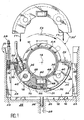
- the support devices 12 are identical and only one of them is illustrated in Figure 1.
- Each support device 12 comprises a fixed body 16 which has on its upper face a concave bearing surface 18.
- the concave bearing surface 18 is at most semi-circular.
- the body fixed 16 is in the form of a block whose horizontal underside rests in the bottom of a trench 20 formed in a fixed frame 22. Maintaining in position of the fixed body 16 in the trench 20 is ensured by the engagement of ribs 23 formed on the lateral faces of this body, in vertical grooves 24 practiced in the side walls of the trench 20. Centering of the fixed body 16 is ensured by a centering finger 26 which projects vertically down from the underside of the body fixed and enters a complementary vertical hole 28 formed in the bottom of trench 20.
- the support device 12 further comprises an interchangeable support member 30.
- This member 30 is mainly formed by a plate 31 which has section in the plane of Figure 1, that is to say according to a plane perpendicular to the axis of rotation 14, the shape of a circular crown sector bounded by two rays forming between them a maximum angle of 180 °. More specifically, the diameter of the outer surface of plate 31 is slightly less than the diameter of the concave bearing surface 18 of the fixed body 16 and the diameter of the inner surface of the plate 31 is slightly larger than the outside diameter of the rotating part 10. This dimensioning of the plate 31 allows the interchangeable support member 30 to be received between the concave bearing surface 18 of the fixed body 16 and the rotating part 10 to be supported, when the support device is in its working state. In addition, the arrangement described allows pivoting of the interchangeable support member 30 between the fixed body 16 and the rotating part 10, around the axis of rotation 14 of the latter.
- the interchangeable support member 30 is in contact with the concave bearing surface 18 of the body fixed 16 by pads 32 formed directly on the outer surface of plate 31 or attached to this surface, as illustrated in FIG. 1.
- the pads 32 are made in one anti-seize material.
- the skates can be replaced by rotating rollers.
- the pads 32 are circumferentially distributed over all the outer surface of the support member 30, to provide a secure and stable support of this organ on the concave bearing surface 18 of the fixed body 16. In order to ensure satisfactory positioning, the pads 32 are at least three in number. In the embodiment illustrated in FIG. 1, the plate 31 is with four pads 32.
- means are also designed to prevent any displacement of the support member interchangeable 30 with respect to the fixed body 16 parallel to the axis of rotation 14 of the rotating part, in the operating state of the device support.
- these means are constituted by two lateral flanges 34 which project radially outwards, on each faces of the plate 31 parallel to the plane of the Figure 1, i.e. perpendicular to the axis of rotation 14 of the rotating part 10.
- These flanges lateral 34 are normally supported on the sides of the fixed body 16, that is to say on the faces of this body parallel to the plane of Figure 1, when the device support 12 occupies its operating state. All relative displacement between the interchangeable support member 30 and the fixed body 16, parallel to the axis of rotation 14, is thus prevented.
- the interchangeable support member 30 comprises two rollers 36 on which the rotating part 10 rests so that it can rotate freely, without friction, around its axis of rotation 14.
- Each rollers 36 is received in a recess 38 formed in the plate 31.
- the latter supports the axes 40 of the rollers, which are oriented parallel to the axis of rotation 14 of the rotating part 10. More precisely, the mounting of the rollers 36 on the plate 31 is such that the rollers can rotate freely relative to this plate and let them protrude slightly beyond the inner surface of the plate 31.
- the rollers 36 are arranged in locations located symmetrically with respect to a vertical plane center of the interchangeable support member 30, this plane being perpendicular to the plane of Figure 1 and containing the axis of rotation 14.
- the number rollers 36 can be greater than two, without departing from the scope of the invention.
- the interchangeable support member 30 also includes a thrust roller 42, which provides a rolling contact between an end flange 44 of the rotating part 10 and the support device 12. This arrangement prevents movement of the rotating part 10 relative to the support device, parallel to the axis of rotation 14, without introducing friction between the two parts.
- the thrust roller 42 is placed in a housing 46 machined on the inner surface of the plate 31, and it is mounted on the latter by an axis 48 oriented radially with respect to the axis of rotation 14 of the rotating part 10, so that it can rotate freely in plate 31.
- axis 48 of the thrust roller 42 is advantageously placed in the aforementioned plane of symmetry of the interchangeable rotating part 30, perpendicular to the plane of Figure 1 and containing the axis of rotation 14 of the rotating part 10.
- the support device further includes unlockable fastening means 50, of the interchangeable support member 30 on the fixed body 16.
- These unlockable fixing means are normally locked, in order to immobilize the interchangeable support member 30 relative to the fixed body 16. They comprise two identical structures, arranged symmetrically to the vertical plane median perpendicular to the plane of Figure 1 and containing the axis of rotation 14 of the rotating part 10. In Figure 1, only the structure on the left of unlockable fixing means 50 has been illustrated. Under normal operating conditions, will understand that an identical structure is on the right part of the device, between the support member 30 and the fixed body 16.
- Each of the two structures constituting the fastening means 50 includes a plate 52, normally blocked by a fixing member, such as a screw 54, on the corresponding end face of the fixed body 16, that is to say on the upper face of the latter extending the concave bearing surface 18, beyond the corresponding circumferential end of this area.
- a fixing member such as a screw 54
- the support device 12 further comprises connecting means 56, designed to allow the support member to be coupled end to end interchangeable 30 and a replacement support member 30 'identical to the interchangeable support member 30, when the latter must be replaced.
- the connecting means 56 comprise two identical structures, designed to be interposed between the ends facing the two bodies support 30 and 30 ', in order to couple them to each other to form a crown completely encircling the rotating part 10 as illustrated diagrammatically in phantom in Figure 1.
- the two structures forming the connecting means 56 are then arranged symmetrically with respect to a perpendicular plane in the plane of Figure 1 and containing the axis of rotation 14 of the rotating part. Only the structure on the right of these connecting means 56 has been illustrated schematically in Figure 1.
- each structure forming the connecting means 56 comprises a key 58 in the form of a plate able to be interposed between the ends in vis-à-vis the interchangeable support member 30 and the replacement support member 30 '.
- This brochure has, on each of its faces, at least two pawns positioning 60, which project radially from so as to be able to penetrate into holes 62 formed in the ends facing the support members 30 and 30'.
- Each of the structures forming the means link 56 also includes a locking member 64 comprising at least two keys 66. These keys 66 are intended to be engaged in holes 68 machined in the lateral faces of the members support 30 and 30 'to be coupled, after the keys 58 have been put in place. Efficient coupling of support members 30 and 30 'is thus produced.
- radial holes 70 can be machined on the surface exterior of the plate 31 of each of them, as it has been illustrated in Figure 1.
- the rotating part 10 is a tubular furnace used in the nuclear industry
- the invention makes it possible to bring back about 5 weeks to about 1 week time required to replace the rollers.
- the different parts to handle are then provided with known manner, heads facilitating their gripping using remote manipulators.
- the invention is not limited to this application, however, and not only concerns the case where the rotating part is supported by rollers. It applies to contrary to any other type of support (sliding pads, ball or roller bearings, fluid bearings, etc.).
- the support members 30 and 30 are recoverable when their replacement has been done.
- the rollers 36 and 42 are interchangeably mounted on these members supports, by appropriate mechanical means (not shown).
- a support member 30 equipped with rollers 36 and 42 can thus serve as a replacement support member 30 'during a subsequent intervention. This arrangement can significantly reduce the volume of waste as well as the cost of spare parts.
Landscapes
- Engineering & Computer Science (AREA)
- Mechanical Engineering (AREA)
- General Engineering & Computer Science (AREA)
- Rollers For Roller Conveyors For Transfer (AREA)
- Muffle Furnaces And Rotary Kilns (AREA)
- Rolls And Other Rotary Bodies (AREA)
- Drying Of Solid Materials (AREA)
- Coating Apparatus (AREA)
- Crushing And Grinding (AREA)
Claims (10)
- Verfahren zum Ersetzen von Verschleißorganen einer Stützvorrichtung für ein sich drehendes Teil (10) mit gegebener Drehachse (14), wobei die Stützvorrichtung in funktionierendem Zustand umfasst:einen festen Körper (16), welcher eine konkave Stützfläche (18) mit höchstens halbkreisförmigem Querschnitt in einer Ebene senkrecht zur Drehachse (14) aufweist,ein auswechselbares Stützorgan (30), welches ausgestaltet ist, zwischen der konkaven Stützoberfläche (18) und dem zu stützenden Teil (10) aufgenommen zu werden und welches im Querschnitt in genannter Ebene die Form eines Kreisringsektors aufweist, welcher von zwei Radien begrenzt wird, welche zwischen sich einen maximalen Winkel von 180° bilden, undlösbare Befestigungsmittel (50) zum Befestigen des auswechselbaren Stützorgans (30) an dem festen Körper (16); wobei das Verfahren dadurch gekennzeichnet ist, dass es die folgenden Schritte umfasst:Demontage der Befestigungsmittel (50),Stirn-an-Stirn-Koppeln des auswechselbaren Stützorgans (30) und eines Ersatzstützorgans (30') mit Hilfe von Verbindungsmitteln (56),gleichzeitige Drehung der gekoppelten Stützorgane (30, 30') um die Drehachse (14) in einer Weise, dass das Ersatzstützorgan (30') ohne Demontage des sich drehenden Teils an den Platz des auswechselbaren Stützorgans (30) gebracht wird,Demontage der Verbindungsmittel (56) und Wegnehmen des auswechselbaren Stützorgans (30).
- Verfahren gemäß Anspruch 1, wobei die Drehachse des sich drehenden Teils (10) im Wesentlichen horizontal ist und die konkave Stützoberfläche (18) nach oben ausgerichtet ist.
- Verfahren gemäß einem der Ansprüche 1 oder 2, wobei das auswechselbare Stützorgan (30) mindestens zwei Laufrollen (36), auf welchen sich das sich drehende Teil (10) abstützt, mit Achsen, welche parallel zu der Drehachse sind, umfasst.
- Verfahren gemäß Anspruch 3, wobei das auswechselbare Stützorgan (30) weiterhin eine Anschlagrolle (42) umfasst, deren Achse radial in Bezug auf die Drehachse des sich drehenden Teils (10) ausgerichtet ist.
- Verfahren gemäß einem der Ansprüche 3 oder 4, wobei jede der Rollen (36, 42) in demontierbarer Weise an dem auswechselbaren Stützorgan (30) angebracht ist.
- Verfahren gemäß einem der vorhergehenden Ansprüche, wobei das auswechselbare Stützorgan (30) mit der konkaven Stützoberfläche (18) über über den Umfang verteilte Kufen (32) in Kontakt steht.
- Verfahren gemäß einem der vorhergehenden Ansprüche, wobei das auswechselbare Stützorgan (30) laterale Zwischenflansche (34) aufweist, welche ausgelegt sind, sich auf Seiten des festen Körpers (16) abzustützen, um eine Relativbewegung zwischen dem letzteren und dem Stützorgan parallel zu der Drehachse zu verhindern.
- Verfahren gemäß einem der vorhergehenden Ansprüche, wobei die Verbindungsmittel (56) umfassen:Schlüssel (58), welche ausgestaltet sind, zwischen gegenüberliegenden Enden des auswechselbaren Stützorgans (30) und des Ersatzstützorgans (30') dazwischengestellt zu werden, wobei die Schlüssel (58) Positionierungsmetallstücke (60) umfassen, welche in in den Enden ausgebildete Löcher (62) eindringen, undVerriegelungsorgane (64), ausgestattet mit Keilen (60), welche ausgestaltet sind, mit in den lateralen Flächen der zu koppelnden Organe gefertigten Bohrungen (68) in Eingriff zu gelangen.
- Verfahren gemäß einem der vorhergehenden Ansprüche, wobei die Befestigungsmittel (50) Platten (52) umfassen, welche ausgestaltet sind, durch Befestigungsorgane (54) an Endflächen des festen Körpers (16) befestigt zu werden, welche die konkave Stützoberfläche (18) an jedem ihrer umfangsmäßigen Enden in einer Weise verlängern, dass sie in eine stützende Stellung mit Endflächen des auswechselbaren Stützorgans (30) gelangen.
- Verfahren gemäß einem der vorhergehenden Ansprüche, wobei das sich drehende Teil ein Rohrverdampfer bzw. Rohrofen (10) ist.
Applications Claiming Priority (2)
| Application Number | Priority Date | Filing Date | Title |
|---|---|---|---|
| FR9700047 | 1997-01-06 | ||
| FR9700047A FR2758176B1 (fr) | 1997-01-06 | 1997-01-06 | Dispositif support a organes d'usure interchangeables, pour une piece tournante telle qu'un four tubulaire |
Publications (2)
| Publication Number | Publication Date |
|---|---|
| EP0854340A1 EP0854340A1 (de) | 1998-07-22 |
| EP0854340B1 true EP0854340B1 (de) | 2004-07-28 |
Family
ID=9502385
Family Applications (1)
| Application Number | Title | Priority Date | Filing Date |
|---|---|---|---|
| EP98400004A Expired - Lifetime EP0854340B1 (de) | 1997-01-06 | 1998-01-05 | Lager mit austauschbaren Reibbelägen für einen rotierenden Werkstück wie einen Drehrohrofen |
Country Status (7)
| Country | Link |
|---|---|
| US (1) | US5887986A (de) |
| EP (1) | EP0854340B1 (de) |
| JP (1) | JP3971006B2 (de) |
| KR (1) | KR100505128B1 (de) |
| AT (1) | ATE272200T1 (de) |
| DE (1) | DE69825186D1 (de) |
| FR (1) | FR2758176B1 (de) |
Families Citing this family (6)
| Publication number | Priority date | Publication date | Assignee | Title |
|---|---|---|---|---|
| DE19804431A1 (de) * | 1998-02-05 | 1999-08-12 | Motan Fuller Verfahrenstechnik | Zellenradschleuse mit Zusatzlagerung |
| CA2444869A1 (en) * | 2002-10-21 | 2004-04-21 | The Boeing Company | Method and apparatus for actuating movable components, including canards, over multiple ranges |
| DE10256758A1 (de) * | 2002-12-05 | 2004-06-17 | Khd Humboldt Wedag Ag | Befestigung eines Laufringes auf dem Mantel eines Drehrohres |
| US7476034B2 (en) * | 2003-08-28 | 2009-01-13 | Boston Scientific Scimed, Inc. | Dynamic bushing for medical device tubing |
| US20130077910A1 (en) * | 2011-09-23 | 2013-03-28 | Siemens Industry, Inc. | High speed mechanical bearing using fixed rollers |
| CN117884850A (zh) * | 2022-10-08 | 2024-04-16 | 北京天和药玻科技有限公司 | 定位方法及旋转管更换系统 |
Citations (1)
| Publication number | Priority date | Publication date | Assignee | Title |
|---|---|---|---|---|
| GB1076992A (en) * | 1964-07-21 | 1967-07-26 | Ass Elect Ind | Improvements in or relating to bearings for rotating shafts |
Family Cites Families (5)
| Publication number | Priority date | Publication date | Assignee | Title |
|---|---|---|---|---|
| US3015528A (en) * | 1957-08-16 | 1962-01-02 | Davy & United Eng Co Ltd | Thrust bearings |
| US3431034A (en) * | 1967-01-24 | 1969-03-04 | Nordberg Manufacturing Co | Supporting means for bearings and the like |
| FR2169466A5 (de) * | 1972-01-26 | 1973-09-07 | Creusot Loire | |
| DE2254079A1 (de) * | 1972-11-04 | 1974-05-16 | Pohlig Heckel Bleichert | Vorrichtung zum verlagern von sich um ihre laengsachse drehenden trommeln u.ae. zylindrischen koerpern |
| DE3306745A1 (de) * | 1983-02-25 | 1984-08-30 | Krupp Polysius Ag, 4720 Beckum | Lager fuer drehtrommeln |
-
1997
- 1997-01-06 FR FR9700047A patent/FR2758176B1/fr not_active Expired - Fee Related
- 1997-11-25 US US08/978,206 patent/US5887986A/en not_active Expired - Lifetime
-
1998
- 1998-01-05 DE DE69825186T patent/DE69825186D1/de not_active Expired - Lifetime
- 1998-01-05 EP EP98400004A patent/EP0854340B1/de not_active Expired - Lifetime
- 1998-01-05 AT AT98400004T patent/ATE272200T1/de not_active IP Right Cessation
- 1998-01-06 KR KR10-1998-0000082A patent/KR100505128B1/ko not_active Expired - Fee Related
- 1998-01-06 JP JP00110598A patent/JP3971006B2/ja not_active Expired - Fee Related
Patent Citations (1)
| Publication number | Priority date | Publication date | Assignee | Title |
|---|---|---|---|---|
| GB1076992A (en) * | 1964-07-21 | 1967-07-26 | Ass Elect Ind | Improvements in or relating to bearings for rotating shafts |
Also Published As
| Publication number | Publication date |
|---|---|
| EP0854340A1 (de) | 1998-07-22 |
| JPH10206589A (ja) | 1998-08-07 |
| DE69825186D1 (de) | 2004-09-02 |
| ATE272200T1 (de) | 2004-08-15 |
| KR19980070348A (ko) | 1998-10-26 |
| US5887986A (en) | 1999-03-30 |
| FR2758176A1 (fr) | 1998-07-10 |
| KR100505128B1 (ko) | 2005-10-19 |
| FR2758176B1 (fr) | 1999-03-05 |
| JP3971006B2 (ja) | 2007-09-05 |
Similar Documents
| Publication | Publication Date | Title |
|---|---|---|
| EP0063993B1 (de) | Lageranordnung, insbesondere für Turbomaschinen | |
| EP2516791B1 (de) | Verfahren für den austausch eines plattenschneiders einer tunnelbohrmaschine, handhabungsvorrichtung und für dieses verfahren geeigneter plattenschneider | |
| CA2929448C (fr) | Porte-outil de coupe pour un tunnelier et ensemble de coupe associe | |
| EP0511496B1 (de) | Rotationsdruckmaschine mit lösbarem Zylinder | |
| EP0854340B1 (de) | Lager mit austauschbaren Reibbelägen für einen rotierenden Werkstück wie einen Drehrohrofen | |
| FR2585789A1 (fr) | Joint pour relier entre eux deux elements de structure d'un vehicule et procede d'assemblage de tels elements | |
| JP3026603B2 (ja) | 車体屈折式車両およびヒンジ組立体 | |
| CA1232147A (en) | Pivot joint | |
| EP0251860B1 (de) | Dichtende Verbindungsvorrichtung für zwei fixierte Rohre | |
| FR2465529A1 (fr) | Ensemble a palier de tourillon de cylindre de laminoir | |
| EP0412908B1 (de) | Schildzapfenlagerung für eine Geschützlafette | |
| JP7164772B2 (ja) | 直列搭載を伴うカッタ筐体 | |
| FR2749358A1 (fr) | Roulement d'orientation de grand diametre | |
| FR2932105A1 (fr) | Dispositif de montage d'un mandrin dans un laminoir, laminoir equipe d'un tel dispositif et mandrin pour un tel laminoir | |
| CA2408955C (en) | Split drive component with maintained alignment | |
| EP1432518B1 (de) | Verschleissplattenverband | |
| FR2576648A1 (fr) | Joint articule entre deux elements de structure et son procede de montage | |
| JP2021071143A (ja) | 軸受構造および滑り軸受の交換方法 | |
| JPH0240839B2 (ja) | Tonnerukutsusakukinokatsutadeisuku | |
| FR2501776A1 (fr) | Stabiliseur non rotatif a palier a rouleaux | |
| FR3064326A1 (fr) | Element d'engrenage a rouleaux | |
| EP0714732B1 (de) | Aufnahmeverfahren eines Werkstücks sowie ein Zahnrad während eines Honvorgangs dessen Bohrung | |
| US7338101B2 (en) | Apparatus and method for handling a crossover tube of a gas turbine | |
| EP0765404A1 (de) | Vorrichtung zum tragen eines drehenden körpers | |
| EP0787965A1 (de) | Trocknungszylinder mit oscillierender Rakelanordnung |
Legal Events
| Date | Code | Title | Description |
|---|---|---|---|
| PUAI | Public reference made under article 153(3) epc to a published international application that has entered the european phase |
Free format text: ORIGINAL CODE: 0009012 |
|
| AK | Designated contracting states |
Kind code of ref document: A1 Designated state(s): AT BE CH DE DK ES FI FR GB GR IE IT LI LU MC NL PT SE |
|
| AX | Request for extension of the european patent |
Free format text: AL;LT;LV;MK;RO;SI |
|
| 17P | Request for examination filed |
Effective date: 19980907 |
|
| AKX | Designation fees paid |
Free format text: AT BE CH DE DK ES FI FR GB GR IE IT LI LU MC NL PT SE |
|
| RBV | Designated contracting states (corrected) |
Designated state(s): AT BE CH DE DK ES FI FR GB GR IE IT LI LU MC NL PT SE |
|
| 17Q | First examination report despatched |
Effective date: 20030812 |
|
| GRAP | Despatch of communication of intention to grant a patent |
Free format text: ORIGINAL CODE: EPIDOSNIGR1 |
|
| GRAS | Grant fee paid |
Free format text: ORIGINAL CODE: EPIDOSNIGR3 |
|
| GRAA | (expected) grant |
Free format text: ORIGINAL CODE: 0009210 |
|
| AK | Designated contracting states |
Kind code of ref document: B1 Designated state(s): AT BE CH DE DK ES FI FR GB GR IE IT LI LU MC NL PT SE |
|
| PG25 | Lapsed in a contracting state [announced via postgrant information from national office to epo] |
Ref country code: NL Free format text: LAPSE BECAUSE OF FAILURE TO SUBMIT A TRANSLATION OF THE DESCRIPTION OR TO PAY THE FEE WITHIN THE PRESCRIBED TIME-LIMIT Effective date: 20040728 Ref country code: IT Free format text: LAPSE BECAUSE OF FAILURE TO SUBMIT A TRANSLATION OF THE DESCRIPTION OR TO PAY THE FEE WITHIN THE PRE;WARNING: LAPSES OF ITALIAN PATENTS WITH EFFECTIVE DATE BEFORE 2007 MAY HAVE OCCURRED AT ANY TIME BEFORE 2007. THE CORRECT EFFECTIVE DATE MAY BE DIFFERENT FROM THE ONE RECORDED.SCRIBED TIME-LIMIT Effective date: 20040728 Ref country code: IE Free format text: LAPSE BECAUSE OF FAILURE TO SUBMIT A TRANSLATION OF THE DESCRIPTION OR TO PAY THE FEE WITHIN THE PRESCRIBED TIME-LIMIT Effective date: 20040728 Ref country code: FI Free format text: LAPSE BECAUSE OF FAILURE TO SUBMIT A TRANSLATION OF THE DESCRIPTION OR TO PAY THE FEE WITHIN THE PRESCRIBED TIME-LIMIT Effective date: 20040728 Ref country code: AT Free format text: LAPSE BECAUSE OF FAILURE TO SUBMIT A TRANSLATION OF THE DESCRIPTION OR TO PAY THE FEE WITHIN THE PRESCRIBED TIME-LIMIT Effective date: 20040728 |
|
| REG | Reference to a national code |
Ref country code: GB Ref legal event code: FG4D Free format text: NOT ENGLISH |
|
| REG | Reference to a national code |
Ref country code: CH Ref legal event code: EP |
|
| REG | Reference to a national code |
Ref country code: IE Ref legal event code: FG4D Free format text: FRENCH |
|
| REF | Corresponds to: |
Ref document number: 69825186 Country of ref document: DE Date of ref document: 20040902 Kind code of ref document: P |
|
| PG25 | Lapsed in a contracting state [announced via postgrant information from national office to epo] |
Ref country code: SE Free format text: LAPSE BECAUSE OF FAILURE TO SUBMIT A TRANSLATION OF THE DESCRIPTION OR TO PAY THE FEE WITHIN THE PRESCRIBED TIME-LIMIT Effective date: 20041028 Ref country code: GR Free format text: LAPSE BECAUSE OF FAILURE TO SUBMIT A TRANSLATION OF THE DESCRIPTION OR TO PAY THE FEE WITHIN THE PRESCRIBED TIME-LIMIT Effective date: 20041028 Ref country code: DK Free format text: LAPSE BECAUSE OF FAILURE TO SUBMIT A TRANSLATION OF THE DESCRIPTION OR TO PAY THE FEE WITHIN THE PRESCRIBED TIME-LIMIT Effective date: 20041028 |
|
| PG25 | Lapsed in a contracting state [announced via postgrant information from national office to epo] |
Ref country code: DE Free format text: LAPSE BECAUSE OF FAILURE TO SUBMIT A TRANSLATION OF THE DESCRIPTION OR TO PAY THE FEE WITHIN THE PRESCRIBED TIME-LIMIT Effective date: 20041029 |
|
| PG25 | Lapsed in a contracting state [announced via postgrant information from national office to epo] |
Ref country code: ES Free format text: LAPSE BECAUSE OF FAILURE TO SUBMIT A TRANSLATION OF THE DESCRIPTION OR TO PAY THE FEE WITHIN THE PRESCRIBED TIME-LIMIT Effective date: 20041108 |
|
| GBT | Gb: translation of ep patent filed (gb section 77(6)(a)/1977) |
Effective date: 20041021 |
|
| NLV1 | Nl: lapsed or annulled due to failure to fulfill the requirements of art. 29p and 29m of the patents act | ||
| PG25 | Lapsed in a contracting state [announced via postgrant information from national office to epo] |
Ref country code: MC Free format text: LAPSE BECAUSE OF NON-PAYMENT OF DUE FEES Effective date: 20050131 Ref country code: LU Free format text: LAPSE BECAUSE OF NON-PAYMENT OF DUE FEES Effective date: 20050131 Ref country code: LI Free format text: LAPSE BECAUSE OF NON-PAYMENT OF DUE FEES Effective date: 20050131 Ref country code: CH Free format text: LAPSE BECAUSE OF NON-PAYMENT OF DUE FEES Effective date: 20050131 Ref country code: BE Free format text: LAPSE BECAUSE OF NON-PAYMENT OF DUE FEES Effective date: 20050131 |
|
| REG | Reference to a national code |
Ref country code: IE Ref legal event code: FD4D |
|
| PLBE | No opposition filed within time limit |
Free format text: ORIGINAL CODE: 0009261 |
|
| STAA | Information on the status of an ep patent application or granted ep patent |
Free format text: STATUS: NO OPPOSITION FILED WITHIN TIME LIMIT |
|
| 26N | No opposition filed |
Effective date: 20050429 |
|
| BERE | Be: lapsed |
Owner name: CIE GENERALE DES MATIERES *NUCLEAIRES Effective date: 20050131 |
|
| REG | Reference to a national code |
Ref country code: CH Ref legal event code: PL |
|
| BERE | Be: lapsed |
Owner name: CIE GENERALE DES MATIERES *NUCLEAIRES Effective date: 20050131 |
|
| PG25 | Lapsed in a contracting state [announced via postgrant information from national office to epo] |
Ref country code: PT Free format text: LAPSE BECAUSE OF NON-PAYMENT OF DUE FEES Effective date: 20041228 |
|
| REG | Reference to a national code |
Ref country code: FR Ref legal event code: PLFP Year of fee payment: 19 |
|
| REG | Reference to a national code |
Ref country code: FR Ref legal event code: PLFP Year of fee payment: 20 |
|
| PGFP | Annual fee paid to national office [announced via postgrant information from national office to epo] |
Ref country code: FR Payment date: 20170131 Year of fee payment: 20 |
|
| PGFP | Annual fee paid to national office [announced via postgrant information from national office to epo] |
Ref country code: GB Payment date: 20170120 Year of fee payment: 20 |
|
| REG | Reference to a national code |
Ref country code: GB Ref legal event code: PE20 Expiry date: 20180104 |
|
| PG25 | Lapsed in a contracting state [announced via postgrant information from national office to epo] |
Ref country code: GB Free format text: LAPSE BECAUSE OF EXPIRATION OF PROTECTION Effective date: 20180104 |