EP0853262B1 - Fixing unit and image forming apparatus - Google Patents
Fixing unit and image forming apparatus Download PDFInfo
- Publication number
- EP0853262B1 EP0853262B1 EP97305103A EP97305103A EP0853262B1 EP 0853262 B1 EP0853262 B1 EP 0853262B1 EP 97305103 A EP97305103 A EP 97305103A EP 97305103 A EP97305103 A EP 97305103A EP 0853262 B1 EP0853262 B1 EP 0853262B1
- Authority
- EP
- European Patent Office
- Prior art keywords
- image forming
- developing agent
- roller
- developing
- unit
- Prior art date
- Legal status (The legal status is an assumption and is not a legal conclusion. Google has not performed a legal analysis and makes no representation as to the accuracy of the status listed.)
- Expired - Lifetime
Links
Images


Classifications
-
- G—PHYSICS
- G03—PHOTOGRAPHY; CINEMATOGRAPHY; ANALOGOUS TECHNIQUES USING WAVES OTHER THAN OPTICAL WAVES; ELECTROGRAPHY; HOLOGRAPHY
- G03G—ELECTROGRAPHY; ELECTROPHOTOGRAPHY; MAGNETOGRAPHY
- G03G15/00—Apparatus for electrographic processes using a charge pattern
- G03G15/20—Apparatus for electrographic processes using a charge pattern for fixing, e.g. by using heat
- G03G15/2003—Apparatus for electrographic processes using a charge pattern for fixing, e.g. by using heat using heat
- G03G15/2014—Apparatus for electrographic processes using a charge pattern for fixing, e.g. by using heat using heat using contact heat
- G03G15/2017—Structural details of the fixing unit in general, e.g. cooling means, heat shielding means
- G03G15/2025—Structural details of the fixing unit in general, e.g. cooling means, heat shielding means with special means for lubricating and/or cleaning the fixing unit, e.g. applying offset preventing fluid
Definitions
- the present invention generally relates to fixing units and image forming apparatuses, and more particularly to a fixing unit which is constructed to clean a fixing heat roller, and to an image forming apparatus which improves the quality of an image formed on a medium by improving cleaning of the fixing heat roller, preventing scattering of a toner within an image forming unit or preventing solidification of a developing agent which is supplied to the image forming unit.
- image forming apparatuses employing electrostatic recording are used as printers and copying machines, and color images are also formed on mediums such as paper.
- a developing agent including a toner is used according to the image forming apparatus employing the electrostatic recording.
- the toner or the developing agent adheres on parts of the image forming apparatus or is scattered, the toner or developing agent that is adhered or scattered interferes with the operation of the parts and stains the medium, thereby deteriorating the quality of the image formed on the medium.
- the developing agent solidifies and it becomes difficult to bring out the original performance of the developing agent and the image forming apparatus.
- a supply reel and a take-up reel are provided for the frieze, and the frieze makes contact with the surface of the fixing heat roller between the supply and take-up reels.
- the cleaning surface of the frieze constantly changes by driving the take-up reel.
- the cleaning capability of the frieze is always high, and the replacement intervals of the frieze is relatively long compared to that of the felt pad.
- US-A-4 939 552 discloses a mechanism in which one direction of the reciprocating movement of a wire is passed to the take-up reel through a chain of gears and a worm speed-reducing mechanism employing a number of worms and worm wheels.
- Another and more specific object of the present invention is to provide an image forming apparatus which forms on a medium an image of an improved quality by taking measures such as positively cleaning stains adhered on parts of the image forming apparatus, preventing scattering of a toner to the parts of the image forming apparatus, and improving a supply of a developing agent even when solidified.
- Still another object of the present invention is to provide a fixing unit which drives a cleaning member for cleaning a fixing heat roller, without the need for a driving source exclusively for the cleaning member and by use of a simple and compact structure, and to provide an image forming apparatus having such a fixing unit.
- the fixing unit and the image forming apparatus of the present invention it is possible to drive the cleaning member which cleans the fixing heat roller by a simple and compact structure, without the need for a driving source exclusively for the driving the cleaning member.
- a fixing unit and an image forming apparatus having the fixing unit are provided with a unidirectional clutch mechanism which intermittently drives a cleaning member, that is, a frieze in a direction to take-up the frieze by using rotation of a fixing heat roller.
- a driving source exclusively for driving the frieze, and the frieze which cleans the fixing heat roller can be driven by a simple and compact structure.
- FIG.1 is a diagram showing the construction of a part of the first embodiment of the image forming apparatus.
- the present invention is applied to a color laser printer.
- this embodiment of the image forming apparatus uses an embodiment of a fixing unit according to the present invention.
- the laser printer shown in FIG.1 is provided with an endless belt transport means 10 for transporting a recording medium such as a recording sheet 9.
- This endless belt transport means 10 includes an endless belt 10a which is made of a flexible dielectric material such as an appropriate synthetic resin material, and the endless belt 10a is provided in a loop around four rollers 10b, 10c, 10d and 10e.
- the roller 10b functions as a driving roller which is driven by an appropriate driving mechanism which is not shown, and drives and transports the endless belt 10a in a direction indicated by an arrow in FIG.1.
- the roller 10c functions as a following roller and also as a charging roller which applies a charge on the endless belt 10a.
- the rollers 10d and 10e both function as guide rollers, and these rollers 10d and 10e are respectively arranged adjacent to the driving roller 10b and the following roller 10c.
- a tension roller 10f is provided between the following roller 10c and the guide roller 10e. This tension roller 10f applies an appropriate tension on the endless belt 10a.
- An upper running part of the endless belt 10a that is, the running part sectioned between the driving roller 10b and the following roller 10c, forms a recording sheet moving path, and the recording sheet 9 is introduced to this recording sheet moving path via the following roller 10c and is ejected via the driving roller 10b.
- the recording sheet 9 When the recording sheet 9 is introduced to the recording sheet moving path via the following roller 10c, the recording sheet 9 is electrostatically adhered on the endless belt 10a due to the charge thereon, and the recording sheet 9 is prevented from changing position with respect to the endless belt 10a.
- An A.C. discharge unit 10g is provided opposite to the driving roller 10b, and the charge on the endless belt 10a is discharged by this A.C. discharge unit 10g. Hence, when the recording sheet 9 is ejected via the driving roller 10b, the recording sheet 9 easily separates from the endless belt 10a.
- the laser printer is provided with four image forming units Y, C, M and B which are arranged in series along the upper running part of the endless belt 10a from the upstream side toward the downstream side in a direction in which the recording sheet 9 is transported.
- the image forming unit Y uses a developing agent including a yellow toner component (Y)
- the image forming unit C uses a developing agent including a cyan toner component (C)
- the image forming unit M uses a developing agent including a magenta toner component (M)
- the image forming unit B uses a developing agent including a black toner component (B).
- the image forming units Y, C, M and B have the same construction, and only differ in that the image forming unit Y records a yellow toner image, the image forming unit C records a cyan toner image, the image forming unit M records a magenta toner image, and the image forming unit B records a black toner image on the recording sheet 9 as the recording sheet moves along the upper running part of the endless belt 10a.
- Each of the image forming units Y, C, M and B is provided with a photoconductive drum 12, and the photoconductive drum 12 is rotated in a direction indicated by an arrow in FIG.1 when carrying out a recording operation.
- a precharge unit 14 made of a corona charger, for example, is arranged above the photoconductive drum 12, and this precharge unit 14 uniformly charges the rotary surface of the photoconductive drum 12.
- a developing unit 18 electrostatically develops the electrostatic latent image written on the photoconductive drum 12 by a predetermined color toner used by the image forming unit.
- This developing unit 18 is arranged on the upstream side of the recording sheet moving path with respect to the photoconductive drum 12.
- the charged toner image on the photoconductive drum 12 is electrostatically transferred onto the recording sheet 9 by a conductive transfer roller 20 which is located under the photoconductive drum 12.
- the conductive transfer roller 20 confronts the photoconductive drum 12 via the upper running part of the endless belt 10a, and applies on the recording sheet which is transported by the endless belt 10a a charge having a polarity opposite to that of the charged toner image, so that the charged toner image is electrostatically transferred onto the recording sheet 9 from the photoconductive drum 12.
- the recording sheet 9 when the recording sheet 9 is input via the following roller 10c of the endless belt transport means 10 and successively passes the image forming units Y, C, M and B, toner images of 4 different colors are successively formed on the recording sheet 9 in an overlapping manner, thereby forming a full-color image. Then, the recording sheet 9 is transported via the driving roller 10b of the endless belt transport means 10 toward a heat roller type thermal fixing unit 22 where the full-color image on the recording sheet 9s is thermally fixed.
- the heat roller type fixing unit 22 includes a heat roller 22a and a back-up roller 22b, and the heat roller 22a and the back-up roller 22b rotate in directions indicated by arrows in FIG.1 when the heat roller type fixing unit 22 operates.
- the recording sheet 9 which is ejected via the driving roller 10b of the endless belt transport means 10 is nipped between the rollers 22a and 22b, and the transferred toner image on the recording sheet is pressed and thermally melted, thereby thermally fixing the toner image on the recording sheet 9.
- a heating means may not only be provided in the heat roller 22a but also in the back-up roller 22b.
- a reference numeral 26 indicates a discharging light emitting element, such as a light emitting diode array, for removing the charge on the surface of the photoconductive drum 12 after the transfer process.
- a reference numeral 28 indicates a developing agent supplying container (hereinafter simply referred to as a hopper) which appropriately supplies the developing agent to the developing unit 18, and a reference numeral 30 indicates an optical density sensor (hereinafter simply referred to as an OD sensor).
- FIG.2 shows, in part, one of the image forming units Y, C, M and B which are arranged above the endless belt transport means 10.
- the recording sheet moving path which is formed by the upper running part of the endless belt 10a is indicated by a one-dot chain line.
- the developing unit 18 includes a developing agent storage container 32, and a two-component developing agent made of a toner component (fine powder particles of coloring resin) and a magnetic component (fine magnetic carriers) is stored in this developing agent storage container 32.
- the developing agent storage container 32 includes a first bottom wall portion 32a, a first rear wall portion 32b extending upward from the rear of the first bottom wall portion 32a, a second bottom wall portion 32c extending horizontally at the upper end of the first rear wall portion 32b, a second rear wall portion 32d extending upward from the rear of the second bottom wall portion 32c, a top wall portion 32e extending frontward and horizontally from the upper end of the second rear wall portion 32d, and a front wall portion 32f extending downward from the front end of the top wall portion 32e, and both ends of the above wall portions are integrally formed with side wall portions (not shown).
- the developing agent storage container 32 has an opening formed between the front end of the first bottom wall portion 32a and the lower end of the front wall portion 32f, and a magnet roller, that is, a developing roller 34, is arranged within this opening so as to expose a portion of the surface of the developing roller 34.
- the developing roller 34 includes a shaft 34a which is fixedly supported by both the side wall portions of the developing agent storage container 32, a core part 34b which is made of a magnetic material and is fixed on the shaft 34a, and a sleeve 34c which is made of a non-magnetic material such as aluminum and is arranged in a rotatable manner on the periphery of the core part 34b.
- the sleeve 34c rotates in a direction indicated by an arrow in FIG.2.
- the exposed surface of the developing roller 34 that is, the sleeve 34c, confronts an electrostatic image bearing member such as the photoconductive drum 12.
- the first bottom wall portion 32a of the developing agent storage container 32 forms a developing agent accumulation 36, and a paddle roller 38 is provided within this developing agent accumulation 36.
- the paddle roller 38 is rotatably supported by both the side wall portions of the developing agent storage container 32, and rotates in a direction indicated by an arrow in FIG.2 when the developing unit 18 operates.
- the paddle roller 38 supplies the developing agent within the developing agent accumulation 36 toward the developing roller 34, and a magnetic brush is formed around the developing roller 34 by the magnetic component, that is, the magnetic carrier of the developing agent.
- the toner component electrostatically adheres on the magnetic brush, and is transported to the confronting developing region of the photoconductive drum 12 as the developing roller 34 rotates.
- a developing agent restriction blade 40 is mounted on a front edge of the first bottom wall portion 32a.
- the second bottom wall portion 32c of the developing agent storage container 32 forms a developing agent agitating part 42 located above the developing agent accumulation 36, and a developing agent agitator 44 is provided in this developing agent agitating part 42.
- the developing agent agitator 44 includes a pair of transport screws 44a and 44b extending between both the side wall portions of the developing agent storage container 32.
- the transport screws 44a and 44b are arranged parallel to each other.
- a pair of curved recesses are formed on the top surface of the second bottom wall portion 32c for receiving spiral blades of the pair of transport screws 44a and 44b, and shaft parts of the transport screws 44a and 44b are rotatably supported by both the side wall portions of the developing agent storage container 32.
- the transport screws 44a and 44b rotate in mutually opposite directions indicated by arrows in FIG.2.
- the spiral blades of the transport screws 44a and 44b are formed spirally clockwise, and thus, the transport screw 44a transports the developing agent rearward with respect to the paper in FIG.2 while the transport screw 44b transports the developing agent frontward with respect to the paper in FIG.2.
- a pair of partitioning plates 46a and 46b which stand from the second bottom wall portion 32c are arranged between the transport screws 44a and 44b.
- the length of the pair of partitioning plates 46a and 46b is shorter than the length of the pair of transport screws 44a and 44b, and a predetermined gap is formed between the ends of the partitioning plates 46a and 46b and the corresponding side wall portions of the developing agent storage container 32.
- a developing agent circulation path is formed at the second bottom wall portion 32c of the developing agent storage container 32 by the transport screws 44a and 44b.
- the developing agent when the developing agent is transported to the one end of the transport screw 44b, the developing agent moves to the one end of the transport screw 44a via the other corresponding end of the partitioning plates 46a and 46b, so that the developing agent is circulated along the pair of transport screws 44a and 44b.
- a communication path 48 which communicates the developing agent accumulation 36 and the developing agent agitating part 42 is formed between the pair of partitioning plates 46a and 46b.
- An upper opening of this communication path 48 forms a developing agent overflow exit with respect to the developing agent within the developing agent storage container 32.
- the partitioning plate 46b is lower than the partitioning plate 46a, thereby forming a developing agent overflow edge by an upper edge of the partitioning plate 46b.
- a part of the developing agent which is circulated by the transport screws 44a and 44b overflows from the upper edge of the partitioning plate 46b, that is, the developing agent overflow edge, and falls into the communication path 48.
- the developing agent accumulation 36 receives the supply of the developing agent from the developing agent agitating part 42.
- a vertical partitioning wall portion 32g is integrally formed on the front wall portion of the second bottom wall portion 32c of the developing agent storage container 32.
- a developing agent rising path 50 is formed between the vertical partitioning wall portion 32g and the front wall portion 32f, and as shown in FIG.2, this developing agent rising path 50 is located immediately above the developing roller 34.
- Two magnet transport rollers 52 and 54 are arranged within the developing agent rising path 50 in a vertical direction with respect to the developing roller 34.
- the magnet transport rollers 52 and 54 have a construction similar to that of the developing roller 34 which is formed as a magnet roller.
- the magnet transport roller 52 includes a shaft 52a which is fixedly supported by both the side wall portions of the developing agent storage container 32, a core part 52b which is made of a magnetic material and is fixed on the shaft 52a, and a sleeve 52c which is made of a non-magnetic material such as aluminum and is arranged in a rotatable manner on the periphery of the core part 52b.
- the magnet transport roller 54 includes a shaft 54a which is fixedly supported by both the side wall portions of the developing agent storage container 32, a core part 54b which is made of a magnetic material and is fixed on the shaft 54a, and a sleeve 54c which is made of a non-magnetic material such as aluminum and is arranged in a rotatable manner on the periphery of the core part 54b.
- the sleeves 52c and 54c respectively rotate in opposite directions indicated by arrows in FIG.2.
- the core part 34b of the developing roller 34, the core part 52b of the magnet transport roller 52, and the core part 54b of the magnet transport roller 54 are respectively and locally magnetized along the periphery thereof as shown in FIG.2.
- Such a local magnetization may be realized by locally applying a magnetic field on each of the core parts 34b, 52b and 54b.
- the magnetic poles of the core part 34b of the developing roller 34 are arranged so as to transport the developing agent from the developing agent accumulation 36 to the developing region and to the lower side of the magnet transport roller 52 as the sleeve 34c rotates.
- the magnetic poles of the core part 52b of the magnet transport roller 52 are arranged so as to transport the developing agent from the upper side of the developing roller 34 upward to the lower side of the magnet transport roller 54 as the sleeve 52c rotates.
- the magnetic poles of the core part 54b of the magnet transport roller 54 are arranged so as to transport the developing agent from the upper side of the magnet transport roller 52 upward to the upper side of the magnet transport roller 54 as the sleeve 54c rotates.
- a scraper member 56 is mounted on the upper end of the vertical partitioning wall portion 32g.
- the front end edge of the scraper member 56 engages the magnet transport roller 54 at a part which is slightly on the rear side from the top part.
- the developing agent which reaches the upper side of the magnet transport roller 54 is supplied to the side of a transport screw 44a of the developing agent agitating part 42 by the scraper member 56.
- the developing agent is supplied from the developing agent agitating part 42 to the developing agent accumulation 36 via the communication path 48, and is then transported from the developing agent accumulation 36 to the developing region by the developing roller 34. Further, after passing the developing region, the developing agent is successively raised by the magnet transport rollers 52 and 54, and is returned again to the developing agent agitating part 42 via the scraper member 56.
- the developing agent is constantly circulated within the developing agent storage container 32, and the developing agent which is sufficiently agitated is constantly supplied to the developing agent accumulation 36.
- the developing agent which is sufficiently agitated means that the toner component and the magnetic component are subjected to sufficient triboelectrification and the toner component is uniformly distributed within the magnetic component.
- the cleaning unit 24 includes a toner recovery container 24a having an opening for receiving a part of the photoconductive drum 12, a fur brush 24b provided within the toner recovery container 24a adjacent to this opening, a toner scraping blade 24c provided along the upper edge of the opening of the toner recovery container 24a, and a transport screw 24d provided on the bottom part of the toner recovery container 24a.
- the residual toner on the surface of the photoconductive drum 12 is brushed off by the fur brush 24b, and the residual toner which could not be brushed off by the fur brush 24b is scraped off by the toner scraping blade 24c.
- the residual toner removed by the fur brush 24b and the toner scraping blade 24c is once recovered within the toner recovery container 24a, and the recovered toner is transported by the transport screw 24d to a predetermined location from the toner recovery container 24a.
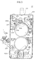
- FIG.3 is a front view, in partial cross section, showing the construction of the fixing unit 22.
- the fixing unit 22 shown in FIG.3 generally includes a housing 221 which forms a cartridge, upper and lower heat rollers 22a and 22b, upper and lower frieze units 222a and 222b, an oil coating unit 223, and a separation finger 224a provided on a tip end of an arm 224 which is pivotally supported on the housing 221.
- the upper frieze unit 222a cleans the surface of the upper heat roller 22a
- the lower frieze unit 222b cleans the surface of the lower heat roller 22b.
- the oil coating unit 223 coats oil on the surface of the upper heat roller 22a, so as to prevent the recording sheet 9 from sticking to the surfaces of the upper and lower heat rollers 22a and 22b.
- the separation finger 224a is provided to separate the recording sheet 9 which is ejected from the fixing unit 22 from an eject path.
- the arm 224 and the separation finger 224a need not be provided on the housing 221, and may be provided independently of the fixing unit 22.
- the upper and lower frieze units 222a and 222b have the same construction, and for this reason, only the construction of the upper frieze unit 222a will be described in this specification.
- the upper frieze unit 222a generally includes a supply reel 225, a take-up reel 226, a pushing mechanism 227, a roller 228, and a frieze (cleaning member) 229 which is made of a material suited for cleaning the surface of the upper heat roller 22a.
- the frieze 229 which is wound on the supply reel 225 in the form of a roll is taken up by the take-up reel 226.
- the roller 228 is provided between the supply reel 225 and the take-up reel 226, and is pushed against the surface of the upper heat roller 22a via the frieze 229 by the pushing mechanism 227 which uses a spring or the like.
- the material used for the frieze 229 is not limited to a specific material, and any known suitable material may be used.
- FIG.4 is a diagram showing a driving part of the upper frieze unit 222a viewed from a rear of the housing 221.
- FIG.5 is a cross sectional view showing the driving part shown in FIG.4 viewed from a top.
- a plate-shaped member 231 shown in FIG.5 is mounted on the housing 221 shown in FIG.3 by a screw or the like.
- a rotary first lever 235, a unidirectional clutch 233, a gear 234, a rotary second lever 232, and a unidirectional clutch 230 are mounted on the plate-shaped member 231.
- the unidirectional clutch 230 is provided at a fulcrum of the second lever 232.
- This unidirectional clutch 230 is connected to the take-up reel 226.
- a tip end of the second lever 232 engages the gear 233 which has a D-shaped cutout 233-1.
- the gear 233 engages the unidirectional clutch 234 which has a diameter smaller than that of the gear 233.
- the unidirectional clutch 234 is mounted on the first lever 235, and the first lever 235 pivots when the unidirectional clutch 234 turns.
- a tip end of the first lever 235 engages a shaft 239 of the upper heat roller 22a.
- the shaft 239 has a D-shaped cutout 239-1.
- a unidirectional clutch mechanism which is made up of two unidirectional clutches is formed by the first lever 235, the unidirectional clutch 234, the gear 233, the second lever 232 and the unidirectional clutch 230.
- the first lever 235 pivots every time the tip end of the first lever 235 engages the D-shaped cutout 239-1 of the shaft 239, and the unidirectional clutch 234 makes a corresponding turn in the counterclockwise direction.
- the gear 233 makes an intermittent turn responsive to the intermittent turn of the unidirectional clutch 234.
- the second lever 232 intermittently turns clockwise every time the tip end of the second lever 232 engages the D-shaped cutout 233-1 of the gear 233.
- the unidirectional clutch 230 which is fixed at the fulcrum of the second lever 232 makes an intermittent turn, and intermittently rotates the take-up reel 226.
- the rotation of the upper heat roller 22a is greatly reduced and transmitted intermittently to the take-up reel 226. Accordingly, it is possible to drive the take-up reel 226 using the rotation of the upper heat roller 22a by a simple structure, so that the take-up reel 226 rotates at a low speed.
- a distance between the outer peripheral surface of the shaft 239 and the surface of the D-shaped cutout 239-1 is 3.5 mm
- the first lever 235 pivots approximately 7° by engaging the D-shaped cutout 239-1
- each of the unidirectional clutches 230 and 234 has a minimum operating angle of 2°.
- the gear 233 has 66 teeth and the gear 233 turns by one tooth during one pivotal movement of the first lever 235, the gear 233 makes one revolution when the first lever 235 makes 66 pivotal movements.
- the unidirectional clutch mechanism having the above described construction can guarantee the minimum feeding amount, that is, 8 mm, of the frieze 229 to be fed when 5000 recording sheets 9 having the A4 size are printed.
- the minimum feeding amount of the frieze 229 can be set depending on the minimum diameter of the roll of the frieze 229 or an average value of the maximum and minimum diameters of the roll of the frieze 229.
- the unidirectional clutch mechanism may be designed depending on this setting of the minimum feeding amount of the frieze 229.
- the amount of the frieze 229 initially wound on the supply reel 225 is set larger than a feeding amount, that is, the amount of the frieze 229 that will be supplied depending on the total number of revolutions made by the upper heat roller 22a between maintenance times (or during maintenance intervals) of the upper and lower heat rollers 22a and 22b or between replacement times (or during replacement intervals) of the upper and lower heat rollers 22a and 22b.
- a feeding amount that is, the amount of the frieze 229 that will be supplied depending on the total number of revolutions made by the upper heat roller 22a between maintenance times (or during maintenance intervals) of the upper and lower heat rollers 22a and 22b or between replacement times (or during replacement intervals) of the upper and lower heat rollers 22a and 22b.
- this second embodiment of the image forming apparatus is basically the same as the construction shown in FIG.1, and an illustration and description of the general construction will be omitted for this second embodiment.
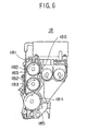
- FIG.6 is a cross sectional view of the developing unit 18 viewed from the front
- FIG.7 shows a part of the developing unit 18 viewed from the top.
- the developing unit 18 shown in FIGS.6 and 7 generally includes a block 181, sealing members 182, transport rollers 183, a developing roller 184, a toner scattering preventing member 185, and a scraper 186. Other parts of the developing unit 18 may essentially be the same as those of the developing unit 18 shown in FIG.2.
- the pair of transport rollers 183 transport the developing agent to the developing roller 184. Ends of the pair of transport rollers 183 are respectively supported by the single block 181.
- the sealing member 182 is provided to prevent scattering of the toner of the developing agent from the ends of the pair of transport rollers 183. Because the sealing member 182 is provided on the inner wall of the single block 181, it is possible to realize the developing unit 18 which can positively prevent the scattering of the toner by a simple construction.
- the material used for the block 181 is not limited to a specific material.
- the material used for the sealing member 182 is also not limited to a specific material.
- this third embodiment of the image forming apparatus is basically the same as the construction shown in FIG.1, and an illustration and description of the general construction will be omitted for this third embodiment.
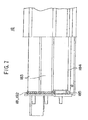
- FIG.8 is a cross sectional view of the hopper 28 viewed from the front.
- the hopper 28 generally includes a hopper casing 281 having an upper opening 280 and a lower opening 282, a lid 283 which can be opened and closed and is provided so as to cover the lower opening 282, a driving shaft 284 for opening and closing the lid 283, a pair of sliders 285 slidably provided on the inner wall of the hopper casing 281, a plurality of projections 286 provided on the sliders 285, hooks 287 for linking the sliders 285 and the lid 283, a cap 288 for closing the upper opening 280, and springs 289 for resiliently linking the sliders 285 to the inner wall of the hopper casing 281.
- the lower opening 282 communicates to the corresponding developing unit 18.
- the shaft 284 is rotated manually or by a driving source such as a motor 300, and the lid 283 is opened or closed depending on the rotation of the shaft 284. Normally, the lid 283 is closed, and the lid 283 is opened when it becomes necessary to supply the developing agent to the corresponding developing unit 18.
- a CPU or the like within the laser printer manages replacement or supply times of the developing agent within the developing unit 18, and the CPU automatically drives the motor 300 when it is time to supply the developing agent to the developing unit 18.
- the developing agent stored within the hopper casing 281 solidifies with time.
- the sliders 285 slide in directions indicated by arrows in FIG.8 via the hooks 287 when the lid 283 is opened or closed.
- the solidified developing agent is softened and stirred by the projections 286 provided on the sliders 285, and the developing agent is smoothly and stably supplied to the corresponding developing unit 18 when the lid 283 is open.
- a developing agent agitating mechanism is formed by the sliders 285, the projections 286 and the springs 289.
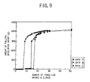
- FIG.9 shows the relationship between an amount of falling developing agent from the hopper 28 and a number of times the lid 283 is opened and closed, with respect to experimental results obtained for three samples. As shown in FIG.9, it was confirmed that the amount of the developing agent supplied stabilizes when the lid 283 is opened and closed 30 or more times.
- FIG.10 is a diagram showing a modification of the hopper 28 shown in FIG.8.
- those parts which are the same as those corresponding parts in FIG.8 are designated by the same reference numerals, and a description thereof will be omitted.
- the hopper 28 shown in FIG.19 is further provided with a spring 290 which links the hooks 287.
- this spring 290 By the provision of this spring 290, it is possible to more positively agitate the developing agent in the vicinity of the lower opening 282.
- the present invention is not limited to application to the laser printer, and is similarly applicable to other image forming apparatuses such as a copying machine.
- the image forming apparatus is not limited to a color image forming apparatus, and the present invention is also applicable to an image forming apparatus having one or a plurality of image forming units.
Description
- The present invention generally relates to fixing units and image forming apparatuses, and more particularly to a fixing unit which is constructed to clean a fixing heat roller, and to an image forming apparatus which improves the quality of an image formed on a medium by improving cleaning of the fixing heat roller, preventing scattering of a toner within an image forming unit or preventing solidification of a developing agent which is supplied to the image forming unit.
- Recently, image forming apparatuses employing electrostatic recording are used as printers and copying machines, and color images are also formed on mediums such as paper. However, according to the image forming apparatus employing the electrostatic recording, a developing agent including a toner is used. For this reason, when the toner or the developing agent adheres on parts of the image forming apparatus or is scattered, the toner or developing agent that is adhered or scattered interferes with the operation of the parts and stains the medium, thereby deteriorating the quality of the image formed on the medium. In addition, when the developing agent is stored for a long period of time, the developing agent solidifies and it becomes difficult to bring out the original performance of the developing agent and the image forming apparatus. Accordingly, there are demands to realize an image forming apparatus which can form the image on the medium with an improved quality, by taking measures such as positively cleaning the stain adhered on the parts of the image forming apparatus, preventing the toner from scattering and adhering on the parts of the image forming apparatus, and preventing solidification of the developing agent.
- Conventionally, as methods of cleaning the fixing heat roller of the fixing unit, there is a method which uses a felt pad, and a method which uses a cleaning member which is often referred to as a frieze. According to the method which uses the felt pad, the felt pad constantly makes contact with the surface of the fixing heat roller so as to remove the toner or the like adhered on the surface of the fixing heat roller. For this reason, the cleaning capability greatly deteriorates when the felt pad becomes stained, and it is necessary to replace the felt pad relatively frequently.
- On the other hand, according to the method which uses the frieze, a supply reel and a take-up reel are provided for the frieze, and the frieze makes contact with the surface of the fixing heat roller between the supply and take-up reels. Hence, the cleaning surface of the frieze constantly changes by driving the take-up reel. As a result, the cleaning capability of the frieze is always high, and the replacement intervals of the frieze is relatively long compared to that of the felt pad.
- However, according to the method which uses the frieze, there were problems in that a driving source is required exclusively for driving the take-up reel and that the construction of the image forming apparatus is complex.
- In addition, although no particular mechanisms have been proposed, a proposal has been made to drive the take-up reel by a mechanism which reduces the rotation of the fixing heat roller. But if the take-up reel were driven by the mechanism which reduces the rotation of the fixing heat roller, the frieze would be used up in a relatively short time because the take-up reel would be driven continuously. It is necessary to rotate the take-up reel extremely slowly compared to the fixing heat roller in order to reduce the amount of frieze that is used up, however, a mechanism which greatly reduces the rotation of the fixing heat roller would become quite bulky and complex, and the use of such a mechanism was not practical particularly in the image forming apparatus or the like which needed to be compact.
- US-A-4 939 552 discloses a mechanism in which one direction of the reciprocating movement of a wire is passed to the take-up reel through a chain of gears and a worm speed-reducing mechanism employing a number of worms and worm wheels.
- Accordingly, it is a general object of the present invention to provide a novel and useful fixing unit and image forming apparatus, in which the problems described above are eliminated.
- Another and more specific object of the present invention is to provide an image forming apparatus which forms on a medium an image of an improved quality by taking measures such as positively cleaning stains adhered on parts of the image forming apparatus, preventing scattering of a toner to the parts of the image forming apparatus, and improving a supply of a developing agent even when solidified.
- Still another object of the present invention is to provide a fixing unit which drives a cleaning member for cleaning a fixing heat roller, without the need for a driving source exclusively for the cleaning member and by use of a simple and compact structure, and to provide an image forming apparatus having such a fixing unit.
- According to the present invention there is provided a fixing unit in accordance with claim 1 and an image forming apparatus in accordance with claim 4.
- According to the fixing unit and the image forming apparatus of the present invention, it is possible to drive the cleaning member which cleans the fixing heat roller by a simple and compact structure, without the need for a driving source exclusively for the driving the cleaning member.
- Other objects and further features of the present invention will be apparent from the following detailed description when read in conjunction with the accompanying drawings.
-
- FIG.1 is a diagram showing the construction of a part of a first embodiment of an image forming apparatus according to the present invention;
- FIG.2 is a diagram showing a part of an image forming unit;
- FIG.3 is a front view, in partial cross section, showing the construction of a fixing unit;
- FIG.4 is a diagram showing a driving part of an upper frieze unit viewed from a rear of a housing;
- FIG.5 is a cross sectional view showing the driving part shown in FIG.4 viewed from a top;
- FIG.6 is a cross sectional view showing a developing unit of a second embodiment of the image forming apparatus according to the present invention viewed from a front;
- FIG.7 is a diagram showing a part of the developing unit shown in FIG.6 viewed from the top;
- FIG.8 is a cross sectional view showing a hopper of a third embodiment of the image forming apparatus according to the present invention viewed from the front;
- FIG.9 is a diagram showing the relationship between an amount of falling developing agent and a number of times a lid is opened and closed; and
- FIG.10 is a diagram showing a modification of the hopper shown in FIG.8.
-
- According to the present invention, a fixing unit and an image forming apparatus having the fixing unit are provided with a unidirectional clutch mechanism which intermittently drives a cleaning member, that is, a frieze in a direction to take-up the frieze by using rotation of a fixing heat roller. According to the present invention, it is unnecessary to provide a driving source exclusively for driving the frieze, and the frieze which cleans the fixing heat roller can be driven by a simple and compact structure.
- First, a description will be given of a first embodiment of the image forming apparatus according to the present invention. FIG.1 is a diagram showing the construction of a part of the first embodiment of the image forming apparatus. In this embodiment of the image forming apparatus, the present invention is applied to a color laser printer. Further, this embodiment of the image forming apparatus uses an embodiment of a fixing unit according to the present invention.
- The laser printer shown in FIG.1 is provided with an endless belt transport means 10 for transporting a recording medium such as a
recording sheet 9. This endless belt transport means 10 includes anendless belt 10a which is made of a flexible dielectric material such as an appropriate synthetic resin material, and theendless belt 10a is provided in a loop around fourrollers endless belt 10a in a direction indicated by an arrow in FIG.1. Theroller 10c functions as a following roller and also as a charging roller which applies a charge on theendless belt 10a. Therollers rollers roller 10c. Atension roller 10f is provided between the followingroller 10c and theguide roller 10e. Thistension roller 10f applies an appropriate tension on theendless belt 10a. An upper running part of theendless belt 10a, that is, the running part sectioned between the driving roller 10b and the followingroller 10c, forms a recording sheet moving path, and therecording sheet 9 is introduced to this recording sheet moving path via the followingroller 10c and is ejected via the driving roller 10b. When therecording sheet 9 is introduced to the recording sheet moving path via the followingroller 10c, therecording sheet 9 is electrostatically adhered on theendless belt 10a due to the charge thereon, and therecording sheet 9 is prevented from changing position with respect to theendless belt 10a. An A.C. discharge unit 10g is provided opposite to the driving roller 10b, and the charge on theendless belt 10a is discharged by this A.C. discharge unit 10g. Hence, when therecording sheet 9 is ejected via the driving roller 10b, therecording sheet 9 easily separates from theendless belt 10a. - The laser printer is provided with four image forming units Y, C, M and B which are arranged in series along the upper running part of the
endless belt 10a from the upstream side toward the downstream side in a direction in which therecording sheet 9 is transported. The image forming unit Y uses a developing agent including a yellow toner component (Y), the image forming unit C uses a developing agent including a cyan toner component (C), the image forming unit M uses a developing agent including a magenta toner component (M), and the image forming unit B uses a developing agent including a black toner component (B). The image forming units Y, C, M and B have the same construction, and only differ in that the image forming unit Y records a yellow toner image, the image forming unit C records a cyan toner image, the image forming unit M records a magenta toner image, and the image forming unit B records a black toner image on therecording sheet 9 as the recording sheet moves along the upper running part of theendless belt 10a. - Each of the image forming units Y, C, M and B is provided with a
photoconductive drum 12, and thephotoconductive drum 12 is rotated in a direction indicated by an arrow in FIG.1 when carrying out a recording operation. Aprecharge unit 14 made of a corona charger, for example, is arranged above thephotoconductive drum 12, and thisprecharge unit 14 uniformly charges the rotary surface of thephotoconductive drum 12. A laser beam LB emitted from an optical write means such as alaser beam scanner 16, for example, writes an electrostatic latent image in a charged region of thephotoconductive drum 12. In other words, the laser beam LB is turned ON/OFF based on binary image data which are obtained from a host unit such as a computer and a word processing system, and writes the electrostatic latent image in the form of a dot image. - A developing
unit 18 electrostatically develops the electrostatic latent image written on thephotoconductive drum 12 by a predetermined color toner used by the image forming unit. This developingunit 18 is arranged on the upstream side of the recording sheet moving path with respect to thephotoconductive drum 12. The charged toner image on thephotoconductive drum 12 is electrostatically transferred onto therecording sheet 9 by aconductive transfer roller 20 which is located under thephotoconductive drum 12. As shown in FIG.1, theconductive transfer roller 20 confronts thephotoconductive drum 12 via the upper running part of theendless belt 10a, and applies on the recording sheet which is transported by theendless belt 10a a charge having a polarity opposite to that of the charged toner image, so that the charged toner image is electrostatically transferred onto therecording sheet 9 from thephotoconductive drum 12. - According to the laser printer having the above described construction, when the
recording sheet 9 is input via the followingroller 10c of the endless belt transport means 10 and successively passes the image forming units Y, C, M and B, toner images of 4 different colors are successively formed on therecording sheet 9 in an overlapping manner, thereby forming a full-color image. Then, therecording sheet 9 is transported via the driving roller 10b of the endless belt transport means 10 toward a heat roller typethermal fixing unit 22 where the full-color image on the recording sheet 9s is thermally fixed. More particularly, the heat rollertype fixing unit 22 includes aheat roller 22a and a back-uproller 22b, and theheat roller 22a and the back-uproller 22b rotate in directions indicated by arrows in FIG.1 when the heat rollertype fixing unit 22 operates. Therecording sheet 9 which is ejected via the driving roller 10b of the endless belt transport means 10 is nipped between therollers recording sheet 9. Of course, a heating means may not only be provided in theheat roller 22a but also in the back-uproller 22b. - On the other hand, in each of the image forming units Y, C, M and B, residual toner which is not transferred onto the
recording sheet 9 after the transfer process, remains adhered on the surface of thephotoconductive drum 12. The residual toner is removed by acleaning unit 24 which is provided on the downstream side of the recording sheet moving path with respect to thephotoconductive drum 12. In FIG.1, areference numeral 26 indicates a discharging light emitting element, such as a light emitting diode array, for removing the charge on the surface of thephotoconductive drum 12 after the transfer process. In addition, areference numeral 28 indicates a developing agent supplying container (hereinafter simply referred to as a hopper) which appropriately supplies the developing agent to the developingunit 18, and areference numeral 30 indicates an optical density sensor (hereinafter simply referred to as an OD sensor). - FIG.2 shows, in part, one of the image forming units Y, C, M and B which are arranged above the endless belt transport means 10. In FIG.2, the recording sheet moving path which is formed by the upper running part of the
endless belt 10a is indicated by a one-dot chain line. As show in FIG.2, the developingunit 18 includes a developingagent storage container 32, and a two-component developing agent made of a toner component (fine powder particles of coloring resin) and a magnetic component (fine magnetic carriers) is stored in this developingagent storage container 32. The developingagent storage container 32 includes a firstbottom wall portion 32a, a firstrear wall portion 32b extending upward from the rear of the firstbottom wall portion 32a, a secondbottom wall portion 32c extending horizontally at the upper end of the firstrear wall portion 32b, a secondrear wall portion 32d extending upward from the rear of the secondbottom wall portion 32c, atop wall portion 32e extending frontward and horizontally from the upper end of the secondrear wall portion 32d, and afront wall portion 32f extending downward from the front end of thetop wall portion 32e, and both ends of the above wall portions are integrally formed with side wall portions (not shown). the developingagent storage container 32 has an opening formed between the front end of the firstbottom wall portion 32a and the lower end of thefront wall portion 32f, and a magnet roller, that is, a developing roller 34, is arranged within this opening so as to expose a portion of the surface of the developing roller 34. The developing roller 34 includes a shaft 34a which is fixedly supported by both the side wall portions of the developingagent storage container 32, a core part 34b which is made of a magnetic material and is fixed on the shaft 34a, and a sleeve 34c which is made of a non-magnetic material such as aluminum and is arranged in a rotatable manner on the periphery of the core part 34b. When the developingunit 18 operates, the sleeve 34c rotates in a direction indicated by an arrow in FIG.2. When the developingunit 18 shown in FIG.2 is arranged within the laser printer, the exposed surface of the developing roller 34, that is, the sleeve 34c, confronts an electrostatic image bearing member such as thephotoconductive drum 12. - The first
bottom wall portion 32a of the developingagent storage container 32 forms a developingagent accumulation 36, and apaddle roller 38 is provided within this developingagent accumulation 36. Thepaddle roller 38 is rotatably supported by both the side wall portions of the developingagent storage container 32, and rotates in a direction indicated by an arrow in FIG.2 when the developingunit 18 operates. Thepaddle roller 38 supplies the developing agent within the developingagent accumulation 36 toward the developing roller 34, and a magnetic brush is formed around the developing roller 34 by the magnetic component, that is, the magnetic carrier of the developing agent. The toner component electrostatically adheres on the magnetic brush, and is transported to the confronting developing region of thephotoconductive drum 12 as the developing roller 34 rotates. In order to restrict the amount of the developing agent which is transported to the developing region by the developing roller 34, a developingagent restriction blade 40 is mounted on a front edge of the firstbottom wall portion 32a. - The second
bottom wall portion 32c of the developingagent storage container 32 forms a developing agent agitating part 42 located above the developingagent accumulation 36, and a developing agent agitator 44 is provided in this developing agent agitating part 42. The developing agent agitator 44 includes a pair of transport screws 44a and 44b extending between both the side wall portions of the developingagent storage container 32. The transport screws 44a and 44b are arranged parallel to each other. As shown in FIG.2, a pair of curved recesses are formed on the top surface of the secondbottom wall portion 32c for receiving spiral blades of the pair of transport screws 44a and 44b, and shaft parts of the transport screws 44a and 44b are rotatably supported by both the side wall portions of the developingagent storage container 32. When the developingunit 18 operates, the transport screws 44a and 44b rotate in mutually opposite directions indicated by arrows in FIG.2. In this embodiment, the spiral blades of the transport screws 44a and 44b are formed spirally clockwise, and thus, the transport screw 44a transports the developing agent rearward with respect to the paper in FIG.2 while the transport screw 44b transports the developing agent frontward with respect to the paper in FIG.2. A pair ofpartitioning plates bottom wall portion 32c are arranged between the transport screws 44a and 44b. The length of the pair ofpartitioning plates partitioning plates agent storage container 32. Hence, a developing agent circulation path is formed at the secondbottom wall portion 32c of the developingagent storage container 32 by the transport screws 44a and 44b. In other words, when the developing agent is transported to from one end to the other end of the transport screw, the developing agent moves to the other end of the transport screw 44b via the corresponding end of thepartitioning plates partitioning plates - A
communication path 48 which communicates the developingagent accumulation 36 and the developing agent agitating part 42 is formed between the pair ofpartitioning plates communication path 48 forms a developing agent overflow exit with respect to the developing agent within the developingagent storage container 32. As shown in FIG.2, thepartitioning plate 46b is lower than thepartitioning plate 46a, thereby forming a developing agent overflow edge by an upper edge of thepartitioning plate 46b. In other words, a part of the developing agent which is circulated by the transport screws 44a and 44b overflows from the upper edge of thepartitioning plate 46b, that is, the developing agent overflow edge, and falls into thecommunication path 48. As a result, the developingagent accumulation 36 receives the supply of the developing agent from the developing agent agitating part 42. - As shown in FIG.2, a vertical partitioning wall portion 32g is integrally formed on the front wall portion of the second
bottom wall portion 32c of the developingagent storage container 32. A developingagent rising path 50 is formed between the vertical partitioning wall portion 32g and thefront wall portion 32f, and as shown in FIG.2, this developingagent rising path 50 is located immediately above the developing roller 34. Twomagnet transport rollers agent rising path 50 in a vertical direction with respect to the developing roller 34. Themagnet transport rollers magnet transport roller 52 includes ashaft 52a which is fixedly supported by both the side wall portions of the developingagent storage container 32, acore part 52b which is made of a magnetic material and is fixed on theshaft 52a, and asleeve 52c which is made of a non-magnetic material such as aluminum and is arranged in a rotatable manner on the periphery of thecore part 52b. Similarly, themagnet transport roller 54 includes ashaft 54a which is fixedly supported by both the side wall portions of the developingagent storage container 32, acore part 54b which is made of a magnetic material and is fixed on theshaft 54a, and asleeve 54c which is made of a non-magnetic material such as aluminum and is arranged in a rotatable manner on the periphery of thecore part 54b. When the developingunit 18 operates, thesleeves core part 52b of themagnet transport roller 52, and thecore part 54b of themagnet transport roller 54 are respectively and locally magnetized along the periphery thereof as shown in FIG.2. Such a local magnetization may be realized by locally applying a magnetic field on each of thecore parts agent accumulation 36 to the developing region and to the lower side of themagnet transport roller 52 as the sleeve 34c rotates. The magnetic poles of thecore part 52b of themagnet transport roller 52 are arranged so as to transport the developing agent from the upper side of the developing roller 34 upward to the lower side of themagnet transport roller 54 as thesleeve 52c rotates. Further, the magnetic poles of thecore part 54b of themagnet transport roller 54 are arranged so as to transport the developing agent from the upper side of themagnet transport roller 52 upward to the upper side of themagnet transport roller 54 as thesleeve 54c rotates. By the above described construction, the developing agent which is transported to the developing region by the developing roller 34 is raised up to the upper side of the topmagnet transport roller 54 without being returned directly to the developingagent accumulation 36. - A
scraper member 56 is mounted on the upper end of the vertical partitioning wall portion 32g. The front end edge of thescraper member 56 engages themagnet transport roller 54 at a part which is slightly on the rear side from the top part. Hence, the developing agent which reaches the upper side of themagnet transport roller 54 is supplied to the side of a transport screw 44a of the developing agent agitating part 42 by thescraper member 56. - Therefore, the developing agent is supplied from the developing agent agitating part 42 to the developing
agent accumulation 36 via thecommunication path 48, and is then transported from the developingagent accumulation 36 to the developing region by the developing roller 34. Further, after passing the developing region, the developing agent is successively raised by themagnet transport rollers scraper member 56. Thus, when the developing unit 19 operates, the developing agent is constantly circulated within the developingagent storage container 32, and the developing agent which is sufficiently agitated is constantly supplied to the developingagent accumulation 36. The developing agent which is sufficiently agitated means that the toner component and the magnetic component are subjected to sufficient triboelectrification and the toner component is uniformly distributed within the magnetic component. - As shown in FIG.2, the
cleaning unit 24 includes atoner recovery container 24a having an opening for receiving a part of thephotoconductive drum 12, afur brush 24b provided within thetoner recovery container 24a adjacent to this opening, atoner scraping blade 24c provided along the upper edge of the opening of thetoner recovery container 24a, and atransport screw 24d provided on the bottom part of thetoner recovery container 24a. The residual toner on the surface of thephotoconductive drum 12 is brushed off by thefur brush 24b, and the residual toner which could not be brushed off by thefur brush 24b is scraped off by thetoner scraping blade 24c. The residual toner removed by thefur brush 24b and thetoner scraping blade 24c is once recovered within thetoner recovery container 24a, and the recovered toner is transported by thetransport screw 24d to a predetermined location from thetoner recovery container 24a. - FIG.3 is a front view, in partial cross section, showing the construction of the fixing
unit 22. The fixingunit 22 shown in FIG.3 generally includes ahousing 221 which forms a cartridge, upper andlower heat rollers lower frieze units oil coating unit 223, and aseparation finger 224a provided on a tip end of anarm 224 which is pivotally supported on thehousing 221. Theupper frieze unit 222a cleans the surface of theupper heat roller 22a, and thelower frieze unit 222b cleans the surface of thelower heat roller 22b. Theoil coating unit 223 coats oil on the surface of theupper heat roller 22a, so as to prevent therecording sheet 9 from sticking to the surfaces of the upper andlower heat rollers separation finger 224a is provided to separate therecording sheet 9 which is ejected from the fixingunit 22 from an eject path. Thearm 224 and theseparation finger 224a need not be provided on thehousing 221, and may be provided independently of the fixingunit 22. - The upper and
lower frieze units upper frieze unit 222a will be described in this specification. Theupper frieze unit 222a generally includes asupply reel 225, a take-upreel 226, a pushingmechanism 227, aroller 228, and a frieze (cleaning member) 229 which is made of a material suited for cleaning the surface of theupper heat roller 22a. Thefrieze 229 which is wound on thesupply reel 225 in the form of a roll is taken up by the take-upreel 226. Theroller 228 is provided between thesupply reel 225 and the take-upreel 226, and is pushed against the surface of theupper heat roller 22a via thefrieze 229 by the pushingmechanism 227 which uses a spring or the like. The material used for thefrieze 229 is not limited to a specific material, and any known suitable material may be used. - FIG.4 is a diagram showing a driving part of the
upper frieze unit 222a viewed from a rear of thehousing 221. In addition, FIG.5 is a cross sectional view showing the driving part shown in FIG.4 viewed from a top. - A plate-shaped
member 231 shown in FIG.5 is mounted on thehousing 221 shown in FIG.3 by a screw or the like. As shown in FIG.4, a rotaryfirst lever 235, aunidirectional clutch 233, agear 234, a rotarysecond lever 232, and aunidirectional clutch 230 are mounted on the plate-shapedmember 231. Theunidirectional clutch 230 is provided at a fulcrum of thesecond lever 232. This unidirectional clutch 230 is connected to the take-upreel 226. A tip end of thesecond lever 232 engages thegear 233 which has a D-shaped cutout 233-1. Thegear 233 engages theunidirectional clutch 234 which has a diameter smaller than that of thegear 233. Theunidirectional clutch 234 is mounted on thefirst lever 235, and thefirst lever 235 pivots when theunidirectional clutch 234 turns. A tip end of thefirst lever 235 engages ashaft 239 of theupper heat roller 22a. Theshaft 239 has a D-shaped cutout 239-1. A unidirectional clutch mechanism which is made up of two unidirectional clutches is formed by thefirst lever 235, theunidirectional clutch 234, thegear 233, thesecond lever 232 and theunidirectional clutch 230. - When the
upper heat roller 22a rotates counterclockwise in FIG.4 as indicated by an arrow, thefirst lever 235 pivots every time the tip end of thefirst lever 235 engages the D-shaped cutout 239-1 of theshaft 239, and theunidirectional clutch 234 makes a corresponding turn in the counterclockwise direction. As a result, thegear 233 makes an intermittent turn responsive to the intermittent turn of theunidirectional clutch 234. Thesecond lever 232 intermittently turns clockwise every time the tip end of thesecond lever 232 engages the D-shaped cutout 233-1 of thegear 233. Hence, theunidirectional clutch 230 which is fixed at the fulcrum of thesecond lever 232 makes an intermittent turn, and intermittently rotates the take-upreel 226. By the unidirectional clutch mechanism having the above described construction, the rotation of theupper heat roller 22a is greatly reduced and transmitted intermittently to the take-upreel 226. Accordingly, it is possible to drive the take-upreel 226 using the rotation of theupper heat roller 22a by a simple structure, so that the take-upreel 226 rotates at a low speed. - For example, it is assumed that a distance between the outer peripheral surface of the
shaft 239 and the surface of the D-shaped cutout 239-1 is 3.5 mm, thefirst lever 235 pivots approximately 7° by engaging the D-shaped cutout 239-1, and each of theunidirectional clutches frieze 229 at least 8 mm every time 5000recording sheets 9 of A4 size are printed. In this case, even when thefirst lever 235 engages the D-shaped cutout 239-1 and pivots by 7°, theunidirectional clutch 234 actually makes a 6° turn. Accordingly, when the inner diameter of theunidirectional clutch 234 is 6 mm, theunidirectional clutch 234 turns by 6π/360·6=0.314 mm in the circumferential direction during one pivotal movement of thefirst lever 235. On the other hand, if it is assumed that thegear 233 has 66 teeth and thegear 233 turns by one tooth during one pivotal movement of thefirst lever 235, thegear 233 makes one revolution when thefirst lever 235 makes 66 pivotal movements. If the inner diameter of theunidirectional clutch 230 is 6 mm, theunidirectional clutch 230 turns by 6π/360·2=0.105 mm in the circumferential direction when thesecond lever 232 engages the D-shaped cutout 233-1 of thegear 233 and turns by 2° to make one pivotal movement. Accordingly, if it is assumed for the sake of convenience that the diameter of the roll of thefrieze 229 wound on the take-upreel 226 is 6 mm and does not change, 0.105 mm of thefrieze 229 is taken up by the take-upreel 226 every time theupper heat roller 22a makes 66 revolutions. - In this case, if it is assumed that the diameter of the
upper heat roller 22a is 80 mm and therecording sheet 9 having the A4 size can be transported along the longer side of therecording sheet 9 in one revolution of theupper heat roller 22a, 5000/66·0.105=8 mm of thefrieze 229 is taken up by the take-upreel 226 when 5000recording sheets 9 having the A4 size are printed. Hence, the unidirectional clutch mechanism having the above described construction can guarantee the minimum feeding amount, that is, 8 mm, of thefrieze 229 to be fed when 5000recording sheets 9 having the A4 size are printed. - When taking into consideration the actual diameter of the roll of the
frieze 229 wound on the take-upreel 226, the minimum feeding amount of thefrieze 229 can be set depending on the minimum diameter of the roll of thefrieze 229 or an average value of the maximum and minimum diameters of the roll of thefrieze 229. The unidirectional clutch mechanism may be designed depending on this setting of the minimum feeding amount of thefrieze 229. - It is desirable that the amount of the
frieze 229 initially wound on thesupply reel 225 is set larger than a feeding amount, that is, the amount of thefrieze 229 that will be supplied depending on the total number of revolutions made by theupper heat roller 22a between maintenance times (or during maintenance intervals) of the upper andlower heat rollers lower heat rollers frieze 229 initially wound on thesupply reel 225 in this manner, it becomes unnecessary to change thefrieze 229 until the maintenance time or the replacement time (end of serviceable life) of the upper andlower heat rollers frieze 229. Furthermore, by making the fixingunit 22 in the form of the cartridge, the replacement of the fixingunit 22 including replacement of thefrieze 229 is facilitated. - Next, a description will be given of a second embodiment of the image forming apparatus according to the present invention. The general construction of this second embodiment of the image forming apparatus is basically the same as the construction shown in FIG.1, and an illustration and description of the general construction will be omitted for this second embodiment.
- In this second embodiment of the image forming apparatus, the developing
unit 18 of each of the image forming units Y, C, M and B has a construction shown in FIGS.6 and 7. FIG.6 is a cross sectional view of the developingunit 18 viewed from the front, and FIG.7 shows a part of the developingunit 18 viewed from the top. - The developing
unit 18 shown in FIGS.6 and 7 generally includes ablock 181, sealingmembers 182,transport rollers 183, a developingroller 184, a tonerscattering preventing member 185, and ascraper 186. Other parts of the developingunit 18 may essentially be the same as those of the developingunit 18 shown in FIG.2. - The pair of
transport rollers 183 transport the developing agent to the developingroller 184. Ends of the pair oftransport rollers 183 are respectively supported by thesingle block 181. The sealingmember 182 is provided to prevent scattering of the toner of the developing agent from the ends of the pair oftransport rollers 183. Because the sealingmember 182 is provided on the inner wall of thesingle block 181, it is possible to realize the developingunit 18 which can positively prevent the scattering of the toner by a simple construction. - The material used for the
block 181 is not limited to a specific material. For example, it is possible to form theblock 181 by an ABS resin. In addition, the material used for the sealingmember 182 is also not limited to a specific material. For example, it is possible to form the sealingmember 182 by a Teflon (registered trademark) felt. - Next, a description will be given of a third embodiment of the image forming apparatus according to the present invention. The general construction of this third embodiment of the image forming apparatus is basically the same as the construction shown in FIG.1, and an illustration and description of the general construction will be omitted for this third embodiment.
- In this third embodiment of the image forming apparatus, the
hopper 28 of each of the image forming units Y, C, M and B has a construction shown in FIG.8. FIG.8 is a cross sectional view of thehopper 28 viewed from the front. - As shown in FIG.8, the
hopper 28 generally includes ahopper casing 281 having anupper opening 280 and alower opening 282, alid 283 which can be opened and closed and is provided so as to cover thelower opening 282, a drivingshaft 284 for opening and closing thelid 283, a pair ofsliders 285 slidably provided on the inner wall of thehopper casing 281, a plurality ofprojections 286 provided on thesliders 285, hooks 287 for linking thesliders 285 and thelid 283, acap 288 for closing theupper opening 280, and springs 289 for resiliently linking thesliders 285 to the inner wall of thehopper casing 281. Thelower opening 282 communicates to the corresponding developingunit 18. Theshaft 284 is rotated manually or by a driving source such as amotor 300, and thelid 283 is opened or closed depending on the rotation of theshaft 284. Normally, thelid 283 is closed, and thelid 283 is opened when it becomes necessary to supply the developing agent to the corresponding developingunit 18. When themotor 30 is used, a CPU or the like within the laser printer manages replacement or supply times of the developing agent within the developingunit 18, and the CPU automatically drives themotor 300 when it is time to supply the developing agent to the developingunit 18. - The developing agent stored within the
hopper casing 281 solidifies with time. However, according to this embodiment, thesliders 285 slide in directions indicated by arrows in FIG.8 via thehooks 287 when thelid 283 is opened or closed. Hence, the solidified developing agent is softened and stirred by theprojections 286 provided on thesliders 285, and the developing agent is smoothly and stably supplied to the corresponding developingunit 18 when thelid 283 is open. In other words, a developing agent agitating mechanism is formed by thesliders 285, theprojections 286 and thesprings 289. - When the developing agent is solidified, it may not be possible to sufficiently soften and stir the developing agent in one opening operation of the
lid 283. Hence, thelid 283 is opened and closed 30 times. FIG.9 shows the relationship between an amount of falling developing agent from thehopper 28 and a number of times thelid 283 is opened and closed, with respect to experimental results obtained for three samples. As shown in FIG.9, it was confirmed that the amount of the developing agent supplied stabilizes when thelid 283 is opened and closed 30 or more times. - Therefore, according to this embodiment, it is possible to positively supply the developing agent from the
hopper 28 to the developingunit 18 of the image forming unit. - FIG.10 is a diagram showing a modification of the
hopper 28 shown in FIG.8. In FIG.10, those parts which are the same as those corresponding parts in FIG.8 are designated by the same reference numerals, and a description thereof will be omitted. - The
hopper 28 shown in FIG.19 is further provided with aspring 290 which links thehooks 287. By the provision of thisspring 290, it is possible to more positively agitate the developing agent in the vicinity of thelower opening 282. - Of course, one of more embodiments described above may be appropriately combined to obtain desired results. In addition, the present invention is not limited to application to the laser printer, and is similarly applicable to other image forming apparatuses such as a copying machine. Moreover, the image forming apparatus is not limited to a color image forming apparatus, and the present invention is also applicable to an image forming apparatus having one or a plurality of image forming units.
- Further, the present invention is not limited to these embodiments, but various variations and modifications may be made without departing from the scope of the present invention.
Claims (6)
- A fixing unit comprising: a fixing heat roller (22a, 22b) capable of rotation and having surface; a first reel (225) supplying a cleaning member (229) which cleans the surface of said fixing heat roller; a second reel (226) taking up the cleaning member from said first reel; and a unidirectional clutch mechanism (230, 232-235) intermittently driving said second reel, characterized in that: said fixing heat roller (22a, 22b) has a shaft (239) with a D-shaped cutout (239-1); and said unidirectional clutch mechanism (230, 232-235) has a lever (235) intermittently pivoted upon contacting the D-shaped cutout of the shaft of said fixing heat roller, during rotation of said fixing heat roller, to intermittently drive said second reel (226) in a direction to take up the cleaning member.
- The fixing unit as claimed in claim 1, characterized in that a total amount of the cleaning member is greater than an amount of the cleaning member supplied depending on a total number of revolutions made by said fixing heat roller (22a, 22b) between maintenance times or between replacement times of said fixing heat roller.
- The fixing unit as claimed in claim 1 or 2, characterized in that said fixing unit comprises a cartridge which is detachably mounted with respect to an image forming apparatus.
- An image forming apparatus comprising: an image forming unit (Y, C, M, B) transferring an image on a medium (9); and a fixing unit (22) according to any of claims 1 to 3 and fixing the image transferred on the medium.
- The image forming apparatus as claimed in claim 4, characterized in that said image forming unit (Y, C, M, B) comprises a developing roller (184); a plurality of transport rollers (183) transporting a developing agent to said developing roller; a single block (181) supporting ends of said plurality of transport rollers; and a sealing member (182) preventing scattering of a toner of the developing agent from the ends of said plurality of transport rollers, said sealing member being provided on said single block.
- The image forming apparatus as claimed in claim 4 or 5, characterized in that there is further provided: a hopper (28) supplying the developing agent to said image forming unit (Y, C, M, B), said hopper comprising a lid (283) which is opened when supplying the developing agent to said image forming unit, and an agitating mechanism (285, 286, 289, 290) mechanically linked to opening of said lid and agitating the developing agent within said hopper.
Applications Claiming Priority (3)
| Application Number | Priority Date | Filing Date | Title |
|---|---|---|---|
| JP170097 | 1997-01-08 | ||
| JP00170097A JP3451867B2 (en) | 1997-01-08 | 1997-01-08 | Fixing unit and image forming apparatus |
| JP1700/97 | 1997-01-08 |
Publications (3)
| Publication Number | Publication Date |
|---|---|
| EP0853262A2 EP0853262A2 (en) | 1998-07-15 |
| EP0853262A3 EP0853262A3 (en) | 1999-11-17 |
| EP0853262B1 true EP0853262B1 (en) | 2003-01-22 |
Family
ID=11508823
Family Applications (1)
| Application Number | Title | Priority Date | Filing Date |
|---|---|---|---|
| EP97305103A Expired - Lifetime EP0853262B1 (en) | 1997-01-08 | 1997-07-10 | Fixing unit and image forming apparatus |
Country Status (4)
| Country | Link |
|---|---|
| US (1) | US6091925A (en) |
| EP (1) | EP0853262B1 (en) |
| JP (1) | JP3451867B2 (en) |
| DE (1) | DE69718611T2 (en) |
Families Citing this family (9)
| Publication number | Priority date | Publication date | Assignee | Title |
|---|---|---|---|---|
| US6532353B1 (en) * | 1999-12-29 | 2003-03-11 | Heidelberger Druckmaschinen Ag | Cleaning web advancement and drive control mechanism |
| US6278860B1 (en) * | 2000-03-31 | 2001-08-21 | Terry Nate Morganti | Castered and gimballed cleaning web with self-tensioning |
| US7299001B2 (en) * | 2003-09-12 | 2007-11-20 | Ricoh Company, Ltd. | Fuser cleaning method and system in image-forming device |
| JP5434430B2 (en) * | 2009-09-18 | 2014-03-05 | 富士ゼロックス株式会社 | Developing device and image forming apparatus |
| US8375855B2 (en) * | 2010-04-06 | 2013-02-19 | Xerox Corporation | Device for cleaning the IOWA roll on a duplexing marking system |
| JP5565801B2 (en) * | 2010-05-13 | 2014-08-06 | シャープ株式会社 | Fixing device and image forming apparatus including the same |
| CN102243464B (en) * | 2010-05-13 | 2015-07-15 | 夏普株式会社 | Fixing apparatus and image forming apparatus including the same |
| JP5121880B2 (en) * | 2010-05-13 | 2013-01-16 | シャープ株式会社 | Fixing device and image forming apparatus including the same |
| JP5121879B2 (en) * | 2010-05-13 | 2013-01-16 | シャープ株式会社 | Fixing device and image forming apparatus including the same |
Family Cites Families (18)
| Publication number | Priority date | Publication date | Assignee | Title |
|---|---|---|---|---|
| JPS5949581B2 (en) * | 1975-06-26 | 1984-12-04 | キヤノン株式会社 | cam control device |
| JPS6079373A (en) * | 1983-10-07 | 1985-05-07 | Fuji Xerox Co Ltd | Developing device |
| US4914481A (en) * | 1987-07-09 | 1990-04-03 | Sharp Kabushiki Kaisha | Developing apparatus |
| US4939552A (en) * | 1987-08-31 | 1990-07-03 | Minolta Camera Kabushiki Kaisha | Copying apparatus with drum or fixing roller cleaning belt driven from document scanner |
| JPH01319775A (en) * | 1988-06-21 | 1989-12-26 | Matsushita Electric Ind Co Ltd | Fixing device |
| JPH02280181A (en) * | 1989-04-20 | 1990-11-16 | Konica Corp | Cleaning device for fixing device |
| JPH0315882A (en) * | 1989-06-14 | 1991-01-24 | Matsushita Electric Ind Co Ltd | Cleaning device for fixing unit |
| JPH03155576A (en) * | 1989-08-10 | 1991-07-03 | Ricoh Co Ltd | Developing device for image forming device |
| JPH0425877A (en) * | 1990-05-21 | 1992-01-29 | Matsushita Electric Ind Co Ltd | Developing device |
| JPH04251271A (en) * | 1991-01-09 | 1992-09-07 | Minolta Camera Co Ltd | Developing device |
| JPH05232833A (en) * | 1992-01-30 | 1993-09-10 | Fuji Xerox Co Ltd | Cleaner for fixing device |
| JPH0611991A (en) * | 1992-06-26 | 1994-01-21 | Canon Inc | Image forming device |
| JPH0651636A (en) * | 1992-07-27 | 1994-02-25 | Ricoh Co Ltd | Developing device |
| JP3021277B2 (en) * | 1993-06-11 | 2000-03-15 | キヤノン株式会社 | Full-color image forming method |
| JP3247250B2 (en) * | 1994-05-17 | 2002-01-15 | キヤノン株式会社 | Image forming device |
| JPH0882998A (en) * | 1994-09-09 | 1996-03-26 | Ricoh Co Ltd | Developing device |
| JPH08101596A (en) * | 1994-09-30 | 1996-04-16 | Ricoh Co Ltd | Thermal roller fixing device |
| JPH09127777A (en) * | 1995-10-30 | 1997-05-16 | Canon Inc | Toner replenishing device and image forming device |
-
1997
- 1997-01-08 JP JP00170097A patent/JP3451867B2/en not_active Expired - Fee Related
- 1997-07-01 US US08/886,417 patent/US6091925A/en not_active Expired - Fee Related
- 1997-07-10 EP EP97305103A patent/EP0853262B1/en not_active Expired - Lifetime
- 1997-07-10 DE DE69718611T patent/DE69718611T2/en not_active Expired - Lifetime
Also Published As
| Publication number | Publication date |
|---|---|
| DE69718611D1 (en) | 2003-02-27 |
| US6091925A (en) | 2000-07-18 |
| DE69718611T2 (en) | 2003-05-22 |
| EP0853262A3 (en) | 1999-11-17 |
| EP0853262A2 (en) | 1998-07-15 |
| JPH10198213A (en) | 1998-07-31 |
| JP3451867B2 (en) | 2003-09-29 |
Similar Documents
| Publication | Publication Date | Title |
|---|---|---|
| JP6911310B2 (en) | Developing equipment and image forming equipment | |
| JPH07209991A (en) | Developing device and recovering method for two-component developer for the device | |
| JP5073418B2 (en) | Lubricant supply structure, cleaning device, and image forming apparatus | |
| US6519428B1 (en) | Image forming apparatus having mixed toner consumption mode | |
| JPH0815935A (en) | Multicolor image forming device | |
| EP0853262B1 (en) | Fixing unit and image forming apparatus | |
| US5581337A (en) | Developing apparatus and image forming apparatus employing mixing balls in the cartridge supply container | |
| JP3510084B2 (en) | Electrostatic recording apparatus having a plurality of developing units | |
| JPH10239970A (en) | Developing device | |
| JP2004109319A (en) | Processor, developing device, image forming apparatus and contamination removing member | |
| CN107918260B (en) | Developing device and image forming apparatus including the same | |
| JP2008197470A (en) | Toner-conveying device and image forming apparatus using the same | |
| JP2012141444A (en) | Image forming apparatus | |
| JP7039926B2 (en) | Transport equipment, developing equipment, and image forming equipment | |
| JP4794772B2 (en) | Image forming apparatus | |
| JP3837815B2 (en) | Developing device and image forming apparatus | |
| JP2024044678A (en) | Image forming device | |
| JPH0437774A (en) | Color image forming device | |
| JPH1138852A (en) | Cleaning device, image forming device and process cartridge | |
| JP2001201942A (en) | Image forming device | |
| JP2006133579A (en) | Developing device and process cartridge | |
| JP4770410B2 (en) | Image forming apparatus | |
| JP2003215879A (en) | Tandem type intermediate transfer device | |
| JP4897443B2 (en) | Cleaning device and image forming apparatus having the same | |
| JP2007271844A (en) | Developer conveying device and image forming apparatus |
Legal Events
| Date | Code | Title | Description |
|---|---|---|---|
| PUAI | Public reference made under article 153(3) epc to a published international application that has entered the european phase |
Free format text: ORIGINAL CODE: 0009012 |
|
| AK | Designated contracting states |
Kind code of ref document: A2 Designated state(s): DE FR GB |
|
| AX | Request for extension of the european patent |
Free format text: AL;LT;LV;RO;SI |
|
| PUAL | Search report despatched |
Free format text: ORIGINAL CODE: 0009013 |
|
| AK | Designated contracting states |
Kind code of ref document: A3 Designated state(s): AT BE CH DE DK ES FI FR GB GR IE IT LI LU MC NL PT SE |
|
| AX | Request for extension of the european patent |
Free format text: AL;LT;LV;RO;SI |
|
| 17P | Request for examination filed |
Effective date: 20000508 |
|
| AKX | Designation fees paid |
Free format text: DE FR GB |
|
| 17Q | First examination report despatched |
Effective date: 20010403 |
|
| GRAG | Despatch of communication of intention to grant |
Free format text: ORIGINAL CODE: EPIDOS AGRA |
|
| GRAG | Despatch of communication of intention to grant |
Free format text: ORIGINAL CODE: EPIDOS AGRA |
|
| GRAH | Despatch of communication of intention to grant a patent |
Free format text: ORIGINAL CODE: EPIDOS IGRA |
|
| GRAH | Despatch of communication of intention to grant a patent |
Free format text: ORIGINAL CODE: EPIDOS IGRA |
|
| GRAA | (expected) grant |
Free format text: ORIGINAL CODE: 0009210 |
|
| AK | Designated contracting states |
Kind code of ref document: B1 Designated state(s): DE FR GB |
|
| REG | Reference to a national code |
Ref country code: GB Ref legal event code: FG4D |
|
| REF | Corresponds to: |
Ref document number: 69718611 Country of ref document: DE Date of ref document: 20030227 Kind code of ref document: P |
|
| REG | Reference to a national code |
Ref country code: GB Ref legal event code: 732E |
|
| ET | Fr: translation filed | ||
| REG | Reference to a national code |
Ref country code: FR Ref legal event code: TP |
|
| PLBE | No opposition filed within time limit |
Free format text: ORIGINAL CODE: 0009261 |
|
| STAA | Information on the status of an ep patent application or granted ep patent |
Free format text: STATUS: NO OPPOSITION FILED WITHIN TIME LIMIT |
|
| 26N | No opposition filed |
Effective date: 20031023 |
|
| PGFP | Annual fee paid to national office [announced via postgrant information from national office to epo] |
Ref country code: FR Payment date: 20110727 Year of fee payment: 15 |
|
| PGFP | Annual fee paid to national office [announced via postgrant information from national office to epo] |
Ref country code: DE Payment date: 20110615 Year of fee payment: 15 Ref country code: GB Payment date: 20110706 Year of fee payment: 15 |
|
| GBPC | Gb: european patent ceased through non-payment of renewal fee |
Effective date: 20120710 |
|
| REG | Reference to a national code |
Ref country code: FR Ref legal event code: ST Effective date: 20130329 |
|
| PG25 | Lapsed in a contracting state [announced via postgrant information from national office to epo] |
Ref country code: DE Free format text: LAPSE BECAUSE OF NON-PAYMENT OF DUE FEES Effective date: 20130201 Ref country code: GB Free format text: LAPSE BECAUSE OF NON-PAYMENT OF DUE FEES Effective date: 20120710 Ref country code: FR Free format text: LAPSE BECAUSE OF NON-PAYMENT OF DUE FEES Effective date: 20120731 |
|
| REG | Reference to a national code |
Ref country code: DE Ref legal event code: R119 Ref document number: 69718611 Country of ref document: DE Effective date: 20130201 |