EP0852634B1 - Process for producing a steel cord - Google Patents
Process for producing a steel cord Download PDFInfo
- Publication number
- EP0852634B1 EP0852634B1 EP96931018A EP96931018A EP0852634B1 EP 0852634 B1 EP0852634 B1 EP 0852634B1 EP 96931018 A EP96931018 A EP 96931018A EP 96931018 A EP96931018 A EP 96931018A EP 0852634 B1 EP0852634 B1 EP 0852634B1
- Authority
- EP
- European Patent Office
- Prior art keywords
- steel cord
- filaments
- wire
- core
- set forth
- Prior art date
- Legal status (The legal status is an assumption and is not a legal conclusion. Google has not performed a legal analysis and makes no representation as to the accuracy of the status listed.)
- Expired - Lifetime
Links
- 229910000831 Steel Inorganic materials 0.000 title claims abstract description 75
- 239000010959 steel Substances 0.000 title claims abstract description 75
- 238000000034 method Methods 0.000 title claims description 23
- 241001589086 Bellapiscis medius Species 0.000 claims abstract description 10
- 230000005012 migration Effects 0.000 abstract description 2
- 238000013508 migration Methods 0.000 abstract description 2
- 238000007493 shaping process Methods 0.000 abstract 2
- 239000002131 composite material Substances 0.000 abstract 1
- 238000004519 manufacturing process Methods 0.000 description 17
- 239000011248 coating agent Substances 0.000 description 4
- 238000000576 coating method Methods 0.000 description 4
- 229910001369 Brass Inorganic materials 0.000 description 3
- 239000010951 brass Substances 0.000 description 3
- 230000006735 deficit Effects 0.000 description 3
- 230000015572 biosynthetic process Effects 0.000 description 2
- 238000010073 coating (rubber) Methods 0.000 description 2
- 238000010276 construction Methods 0.000 description 2
- 239000004033 plastic Substances 0.000 description 2
- 150000001875 compounds Chemical class 0.000 description 1
- 230000006835 compression Effects 0.000 description 1
- 238000007906 compression Methods 0.000 description 1
- 230000001771 impaired effect Effects 0.000 description 1
- 239000000314 lubricant Substances 0.000 description 1
- 238000003825 pressing Methods 0.000 description 1
Images


Classifications
-
- D—TEXTILES; PAPER
- D07—ROPES; CABLES OTHER THAN ELECTRIC
- D07B—ROPES OR CABLES IN GENERAL
- D07B1/00—Constructional features of ropes or cables
- D07B1/06—Ropes or cables built-up from metal wires, e.g. of section wires around a hemp core
- D07B1/0606—Reinforcing cords for rubber or plastic articles
- D07B1/0646—Reinforcing cords for rubber or plastic articles comprising longitudinally preformed wires
- D07B1/0653—Reinforcing cords for rubber or plastic articles comprising longitudinally preformed wires in the core
-
- D—TEXTILES; PAPER
- D07—ROPES; CABLES OTHER THAN ELECTRIC
- D07B—ROPES OR CABLES IN GENERAL
- D07B1/00—Constructional features of ropes or cables
- D07B1/06—Ropes or cables built-up from metal wires, e.g. of section wires around a hemp core
-
- D—TEXTILES; PAPER
- D07—ROPES; CABLES OTHER THAN ELECTRIC
- D07B—ROPES OR CABLES IN GENERAL
- D07B1/00—Constructional features of ropes or cables
- D07B1/06—Ropes or cables built-up from metal wires, e.g. of section wires around a hemp core
- D07B1/0606—Reinforcing cords for rubber or plastic articles
- D07B1/0646—Reinforcing cords for rubber or plastic articles comprising longitudinally preformed wires
-
- D—TEXTILES; PAPER
- D07—ROPES; CABLES OTHER THAN ELECTRIC
- D07B—ROPES OR CABLES IN GENERAL
- D07B3/00—General-purpose machines or apparatus for producing twisted ropes or cables from component strands of the same or different material
-
- D—TEXTILES; PAPER
- D07—ROPES; CABLES OTHER THAN ELECTRIC
- D07B—ROPES OR CABLES IN GENERAL
- D07B7/00—Details of, or auxiliary devices incorporated in, rope- or cable-making machines; Auxiliary apparatus associated with such machines
- D07B7/02—Machine details; Auxiliary devices
- D07B7/025—Preforming the wires or strands prior to closing
-
- D—TEXTILES; PAPER
- D07—ROPES; CABLES OTHER THAN ELECTRIC
- D07B—ROPES OR CABLES IN GENERAL
- D07B2201/00—Ropes or cables
- D07B2201/20—Rope or cable components
- D07B2201/2001—Wires or filaments
- D07B2201/2007—Wires or filaments characterised by their longitudinal shape
-
- D—TEXTILES; PAPER
- D07—ROPES; CABLES OTHER THAN ELECTRIC
- D07B—ROPES OR CABLES IN GENERAL
- D07B2201/00—Ropes or cables
- D07B2201/20—Rope or cable components
- D07B2201/2001—Wires or filaments
- D07B2201/2007—Wires or filaments characterised by their longitudinal shape
- D07B2201/2008—Wires or filaments characterised by their longitudinal shape wavy or undulated
-
- D—TEXTILES; PAPER
- D07—ROPES; CABLES OTHER THAN ELECTRIC
- D07B—ROPES OR CABLES IN GENERAL
- D07B2201/00—Ropes or cables
- D07B2201/20—Rope or cable components
- D07B2201/2015—Strands
- D07B2201/2016—Strands characterised by their cross-sectional shape
- D07B2201/2018—Strands characterised by their cross-sectional shape oval
-
- D—TEXTILES; PAPER
- D07—ROPES; CABLES OTHER THAN ELECTRIC
- D07B—ROPES OR CABLES IN GENERAL
- D07B2201/00—Ropes or cables
- D07B2201/20—Rope or cable components
- D07B2201/2015—Strands
- D07B2201/2019—Strands pressed to shape
-
- D—TEXTILES; PAPER
- D07—ROPES; CABLES OTHER THAN ELECTRIC
- D07B—ROPES OR CABLES IN GENERAL
- D07B2201/00—Ropes or cables
- D07B2201/20—Rope or cable components
- D07B2201/2015—Strands
- D07B2201/2022—Strands coreless
-
- D—TEXTILES; PAPER
- D07—ROPES; CABLES OTHER THAN ELECTRIC
- D07B—ROPES OR CABLES IN GENERAL
- D07B2201/00—Ropes or cables
- D07B2201/20—Rope or cable components
- D07B2201/2015—Strands
- D07B2201/2023—Strands with core
-
- D—TEXTILES; PAPER
- D07—ROPES; CABLES OTHER THAN ELECTRIC
- D07B—ROPES OR CABLES IN GENERAL
- D07B2201/00—Ropes or cables
- D07B2201/20—Rope or cable components
- D07B2201/2015—Strands
- D07B2201/2024—Strands twisted
- D07B2201/2029—Open winding
- D07B2201/2031—Different twist pitch
- D07B2201/2032—Different twist pitch compared with the core
-
- D—TEXTILES; PAPER
- D07—ROPES; CABLES OTHER THAN ELECTRIC
- D07B—ROPES OR CABLES IN GENERAL
- D07B2201/00—Ropes or cables
- D07B2201/20—Rope or cable components
- D07B2201/2015—Strands
- D07B2201/2035—Strands false twisted
-
- D—TEXTILES; PAPER
- D07—ROPES; CABLES OTHER THAN ELECTRIC
- D07B—ROPES OR CABLES IN GENERAL
- D07B2201/00—Ropes or cables
- D07B2201/20—Rope or cable components
- D07B2201/2015—Strands
- D07B2201/2038—Strands characterised by the number of wires or filaments
- D07B2201/2039—Strands characterised by the number of wires or filaments three to eight wires or filaments respectively forming a single layer
-
- D—TEXTILES; PAPER
- D07—ROPES; CABLES OTHER THAN ELECTRIC
- D07B—ROPES OR CABLES IN GENERAL
- D07B2201/00—Ropes or cables
- D07B2201/20—Rope or cable components
- D07B2201/2047—Cores
- D07B2201/2052—Cores characterised by their structure
- D07B2201/2059—Cores characterised by their structure comprising wires
-
- D—TEXTILES; PAPER
- D07—ROPES; CABLES OTHER THAN ELECTRIC
- D07B—ROPES OR CABLES IN GENERAL
- D07B2201/00—Ropes or cables
- D07B2201/20—Rope or cable components
- D07B2201/2095—Auxiliary components, e.g. electric conductors or light guides
- D07B2201/2097—Binding wires
-
- D—TEXTILES; PAPER
- D07—ROPES; CABLES OTHER THAN ELECTRIC
- D07B—ROPES OR CABLES IN GENERAL
- D07B2207/00—Rope or cable making machines
- D07B2207/40—Machine components
- D07B2207/4004—Unwinding devices
- D07B2207/4009—Unwinding devices over the head
-
- D—TEXTILES; PAPER
- D07—ROPES; CABLES OTHER THAN ELECTRIC
- D07B—ROPES OR CABLES IN GENERAL
- D07B2207/00—Rope or cable making machines
- D07B2207/40—Machine components
- D07B2207/4004—Unwinding devices
- D07B2207/4013—Unwinding devices comprising flyer
-
- D—TEXTILES; PAPER
- D07—ROPES; CABLES OTHER THAN ELECTRIC
- D07B—ROPES OR CABLES IN GENERAL
- D07B2501/00—Application field
- D07B2501/20—Application field related to ropes or cables
- D07B2501/2046—Tire cords
-
- Y—GENERAL TAGGING OF NEW TECHNOLOGICAL DEVELOPMENTS; GENERAL TAGGING OF CROSS-SECTIONAL TECHNOLOGIES SPANNING OVER SEVERAL SECTIONS OF THE IPC; TECHNICAL SUBJECTS COVERED BY FORMER USPC CROSS-REFERENCE ART COLLECTIONS [XRACs] AND DIGESTS
- Y10—TECHNICAL SUBJECTS COVERED BY FORMER USPC
- Y10S—TECHNICAL SUBJECTS COVERED BY FORMER USPC CROSS-REFERENCE ART COLLECTIONS [XRACs] AND DIGESTS
- Y10S57/00—Textiles: spinning, twisting, and twining
- Y10S57/902—Reinforcing or tire cords
Abstract
Description
Die Erfindung betrifft ein Verfahren zur Herstellung eines Stahlcords sowie einen nach diesem Verfahren hergestellten Stahlcord.The invention relates to a method for producing a steel cord and a steel cord made by this method.
Stahlcorde als Einlagen in Luftreifen für Kraftfahrzeuge zur Verbesserung deren Fahreigenschaften, Dynamik, Stabilität und zur Verlängerung ihrer Lebensdauer sind bekannt und sind üblicherweise aus Litzen aufgebaut, wobei eine Litze ein Bündel aus mindestens zwei, im Regelfall jedoch mehreren Einzeldrähten ist, die umeinander gelegt und/oder umeinander verdreht sind. Die Herstellung erfolgt dabei mittels einer Verlitzmaschine und ist recht aufwendig.Steel cords as inserts in pneumatic tires for motor vehicles for improvement their driving characteristics, dynamics, stability and extension their lifespan are known and are usually made of strands constructed, one strand a bundle of at least two, usually however, there is several individual wires that are laid around and / or are twisted around each other. The production takes place by means of a Bunching machine and is quite complex.
Des weiteren sind Stahlcorde bekannt, deren Seele aus einem zentralen, gefachten Drahtbündel besteht, welches nicht mehr in einem separaten Verlitzprozeß hergestellt wird, sondern unmittelbar beim Verseilen gebildet werden kann.Steel cords are also known, their soul from a central, folded wire bundle, which is no longer in a separate Stranding process is produced, but immediately during stranding can be formed.
Aus der DE-A 26 19 086 ist ein Verfahren zur Herstellung eines Stahlcords bekannt, bei dem mehrere als Seelenfilamente dienende Drahtfilamente von Spulen abgezogen werden. Die Seelenfilamente werden zu einem Strang zusammengefaßt und an den Kanten eines Führungsauges scharf abgebogen und dabei schraubenförmig verformt. In prinzipiell gleicher Weise wird ein Hülldraht, der von einer Spule abgezogen wird, ebenfalls schraubenförmig an den Kanten eines weiteren Führungsauges scharf abgebogen und dabei ebenfalls schraubenförmig verformt. Die gemeinsam gebogenen Seelenfilamente werden am Seilbildungspunkt von den vorgeformten Hülldrähten umwickelt. Das dadurch erhaltene Seil läuft über ein Rollenpaar zu einer Falschdrallvorrichtung, der den erhaltenen Stahlcord plastisch verformt und die vorhandenen Resttorsionsspannungen reduziert. Bei dem bekannten Verfahren kann es zur Beeinträchtigung der Messingbeschichtung der Drahtfilamente durch die an den Kanten des Führungsauges bewirkte schraubenförmige Verformung kommen. Die Beeinträchtigung der Messingbeschichtung führt zu einer Beeinträchtigung der Haftung mit dem Reifengummi. Weiterhin kann es bei dem Herstellungsverfahren zur Beeinträchtigung der Einzelfilamente kommen, wenn lokale Druckstellen auftreten. Hierdurch wird die Ermüdungsfestigkeit beeinträchtigt, wodurch die Einzelfilamente für zyklische Belastungen ungeeignet werden, da derartige lokale Verformungen Ausgangspunkte für das Auftreten von Ermüdungsbrüchen sind.DE-A 26 19 086 describes a method for producing a Steel cords are known in which several serve as soul filaments Wire filaments are pulled off the spools. The soul filaments are combined into a strand and on the edges of a Guide eyes sharply bent and deformed helically. In principle, a sheathed wire is pulled off a coil is also helical on the edges of another Guide eyes sharply bent and also helical deformed. The soul filaments bent together are on Rope formation point wrapped in the preformed sheathed wires. The the resulting rope runs over a pair of rollers to a false twist device, which plastically deformed the steel cord obtained and the existing ones Residual torsional stresses reduced. In the known method it can affect the brass coating of the Wire filaments caused by those on the edges of the guide eye helical deformation. The impairment of Brass coating leads to an impairment of liability the tire rubber. Furthermore, it can in the manufacturing process The individual filaments are impaired when local pressure points occur occur. This affects the fatigue strength, which makes the individual filaments unsuitable for cyclical loads because such local deformations are the starting points for the Fatigue fractures occur.
Aus der EP 0 492 682 ist ein Herstellungsverfahren für einen Stahlcord
bekannt, bei dem als Seelenfilamente dienende Drahtfilamente von
Spulen abgezogen werden und jeweils um ihre Längsachse tordiert
werden. Die Seelenfilamente werden dann in einer einzigen Ebene
parallel aneinanderliegend zusammengeführt und mit einem Hülldraht
umhüllt. Eines oder mehrere der in einer Ebene angeordneten Kernfilamente
oder die Ebene der Kernfilamente als Ganzes weist elastische
Resttorsionsspannungen auf. Die elastischen Resttorsionsspannungen
sind derart gewählt, daß das Drahtbündel über seine ganze Länge im
wesentlichen flach bleibt, solange keine äußeren Kräfte hieran angreifen.
Größe und Richtung der Resttorsionsspannungen werden dabei so
gewählt, daß sich die elastischen Resttorsionsspannungen der Kernfilamente
mit den Rückstellkräften der Hüllfilamente aufheben. Die Herstellung
derartiger flacher Drahtbündel ist jedoch schwierig und technisch
aufwendig, da die parallelen Einzelfilamente in einer Ebene gehalten
werden müssen.
Der Erfindung liegt die Aufgabe zugrunde, ein Verfahren zur Herstellung eines Stahlcords vorzuschlagen, bei dem keine Beeinträchtigung der Drahtbeschichtung oder lokale Druckstellen auftreten.The invention has for its object a method for manufacturing to propose a steel cord where no interference wire coating or local pressure marks.
Zur Lösung dieser Aufgabe wird ein Verfahren mit den Merkmalen des Patentanspruchs 1 vorgeschlagen. Bei dem erfindungsgemäßen Verfahren werden die Seelenfilamente mittels eines Falschdrallers umeinander verdreht, um eine spiralförmige plastische Verformung zu erhalten. Nach dem Falschdraller werden die spiralförmig vorgeformten Seelenfilamente parallel aneinanderliegend mit mindestens einem Hülldraht umwickelt. Der wesentliche Vorteil des erfindungsgemäßen Herstellungsverfahrens liegt in der schonenden plastischen Verformung der Seelenfilamente mittels eines Falschdrallers, wobei weder eine Beeinträchtigung der Beschichtung noch lokale Druckstellen auftreten. Somit zeichnet sich der nach dem erfindungsgemäßen Verfahren hergestellte Stahlcord durch gute Haftung mit dem Reifengummi und weiterhin durch eine hohe Ermüdungsfestigkeit aus.To solve this problem, a method with the features of Claim 1 proposed. In the method according to the invention are the soul filaments around each other using a false twister twisted to obtain a spiral plastic deformation. After the false twister, the spiral-shaped soul filaments are formed parallel to each other with at least one sheath wire wrapped around. The main advantage of the manufacturing method according to the invention lies in the gentle plastic deformation of the Soul filaments by means of a false twister, with neither impairment local pressure marks still occur in the coating. Consequently stands out the manufactured by the inventive method Steel cord through good grip with the tire rubber and on characterized by high fatigue strength.
In weiterer Ausgestaltung des erfindungsgemäßen Herstellungsverfahrens wird vorgeschlagen, daß in Schritt B zwei, drei oder vier Seelenfilamente gemeinsam umeinander verdreht werden und daß zwei oder mehr Stränge mit zwei, drei oder vier umeinander verdrehten Seelenfilamente in einem zusätzlichen Schritt C zu einer Seele zusammengefaßt werden.In a further embodiment of the manufacturing method according to the invention it is suggested that in step B two, three or four soul filaments twisted together and that two or more strands with two, three or four twisted soul filaments combined in an additional step C to form a soul become.
Gemäß Patentanspruch 4 und 5 kann bei dem erfindungsgemäßen Verfahren vorgesehen sein, daß der Stahlcord derart gedrückt wird, daß er eine ovale Form erhält. Zweckmäßig erfolgt die Verformung durch ein Rollenpaar.According to claims 4 and 5 can in the inventive method be provided that the steel cord is pressed so that it gets an oval shape. The deformation is expediently carried out by a Pair of roles.
Ein nach dem erfindungsgemäßen Verfahren hergestellter Stahlcord weist in seiner einfachsten Form drei Drahtfilamente auf, von welchen zwei Seelenfilamente spiralförmig geformt sind und von einem ebenfalls spiralförmig geformten Hülldraht umgeben sind. Hierbei werden die Seelenfilamente mittels eines Falschdrallers in geeigneter Weise mit der gewünschten Drehzahl umeinander verdreht, um nach dem Falschdraller wieder zueinander parallel, jedoch mit spiralförmiger Vorformung zusammengeführt zu werden. Um dieses Bündel paralleler Seelenfilamente wird ein weiteres Filament mit der gleichen Ganghöhe und Gangrichtung zur Spiralform der Vorformung der Einzelfilamente gelegt. Durch diese erfindungsgemäße Ausbildung eines Drahtbündels werden die Einzelfilamente weder beschädigt noch örtlich verformt, so daß ein derartiger Stahlcord für einen Reifen, insbesondere bei Stauchbeanspruchung, über sehr gute Ermüdungseigenschaften verfügt. A steel cord produced by the method according to the invention has in its simplest form three wire filaments, one of which two soul filaments are spirally shaped and one too spiral-shaped sheathed wire are surrounded. Here are the soul filaments in a suitable manner using a false twister the desired speed twisted around to get after the false twister again parallel to each other, but with spiral preforming to be brought together. To make this bundle more parallel Soul filament becomes another filament with the same pitch and Direction of thread to the spiral shape of the preforming of the individual filaments. This inventive formation of a wire bundle the individual filaments are neither damaged nor deformed locally, so that a steel cord of this type for a tire, in particular when subjected to compression, has very good fatigue properties.
In besonders vorteilhafter Ausgestaltung der Erfindung sind eine oder mehrere Lagen von Hülldrähten vorgesehen, die die mindestens zwei Seelenfilamente umgeben. Dadurch wird ein Drahtbündel für einen Reifencord bereitgestellt, bei welchem die Drähte des Seelenbündels auch bei Anwendung im Reifengürtel nicht aus dem Seilverbund migrieren. Das erfindungsgemäße Drahtbündel kann sehr kostengünstig hergestellt werden, da das Seelenbündel keinen eigenen Arbeitsgang benötigt, sondern in Linie mit der gesamten Herstellung produziert werden kann.In a particularly advantageous embodiment of the invention, one or several layers of sheathed wires are provided which cover the at least two Soul filaments surround. This creates a wire bundle for a tire cord provided, in which the wires of the bundle of souls also Do not migrate from the rope assembly when used in the tire belt. The wire bundle according to the invention can be produced very inexpensively because the bundle of souls does not need its own work process, but be produced in line with the entire production can.
Zur weiteren Lösung der Aufgabe wird gemäß Anspruch 16 ein Stahlcord mit einem Drahtbündel vorgeschlagen, wobei mindestens zwei Drahtfilamente als eine Seele bildende Seelenfilamente bündelförmig aneinanderliegend parallel verlaufen und elastische Resttorsionsspannungen aufweisen, die sich in Verbindung mit den Rückstellkräften mindestens eines die Seelenfilamente umgebenden Hülldrahts aufheben. Das erfindungsgemäße Drahtbündel kann einfach hergestellt werden, da die Drahtfilamente der Seele nicht parallel nebeneinander in einer Ebene liegen, was herstellungstechnisch mit einigem Aufwand verbunden ist, sondern in Form eines Bündels zusammengefaßt werden. Durch die geeignete Wahl der elastischen Resttorsionsspannungen wird eine einfache Verarbeitbarkeit bei der Gummierung erreicht, da das erfindungsgemäße Drahtbündel bei der Gummierung flach liegen bleibt.To further solve the problem is a steel cord according to claim 16 proposed with a wire bundle, with at least two Wire filaments as a soul-forming bundle of soul filaments running parallel to each other and elastic residual torsional stresses have in connection with the restoring forces Pick up at least one sheath wire surrounding the core filaments. The wire bundle according to the invention can be easily produced because the wire filaments of the soul are not parallel in parallel one level, which is technically with some effort is connected, but can be summarized in the form of a bundle. Through the appropriate choice of the residual elastic torsional stresses easy processing with rubber coating is achieved because the wire bundle according to the invention lie flat in the rubber coating remains.
In weiterer vorteilhafter Ausgestaltung der Erfindung weist der Stahlcord eine abgeflachte, im wesentliche ovale Form auf. Diese erfindungsgemäße ovale Form hat für die Anwendung im Reifen erhebliche Vorteile, insbesondere auf Grund der unterschiedlichen Steifigkeit des Stahlcords in radialer und lateraler Richtung. Die abgeflachte, im wesentlichen ovale Form kann beispielsweise durch Zusammendrücken des Stahlcords mit einem Rollenpaar erreicht werden.In a further advantageous embodiment of the invention, the steel cord has a flattened, essentially oval shape. This invention oval shape has significant for use in tires Advantages, especially due to the different stiffness of the Steel cords in radial and lateral directions. The flattened, essentially oval shape can, for example, by squeezing of the steel cord can be reached with a pair of rollers.
Weitere vorteilhafte Ausgestaltungen der Erfindung und des erfindungsgemäßen Verfahrens sind in den Unteransprüchen beschrieben.Further advantageous refinements of the invention and that of the invention Procedures are described in the subclaims.
Die Erfindung wird anhand mehrerer Ausführungsbeispiele in der Zeichnung dargestellt und im folgenden näher erläutert.
- Figur 1
- veranschaulicht in schematischer Darstellung ein erfindungsgemäßes Verfahren zur Herstellung eines erfindungsgemäßen Stahlcords gemäß der Figur 4.
- Figur 2
- veranschaulicht in schematischer Darstellung ein erfindungsgemäßes Verfahren zur Herstellung eines erfindungsgemäßen Stahlcords gemäß der Figur 3.
- Figur 3
- zeigt in schematischer perspektivischer Darstellung einen erfindungsgemäßen Stahlcord mit zwei spiralförmig vorgeformten und parallel aneinanderliegenden Seelenfilamenten, die von einem Hülldraht spiralförmig umgeben sind.
- Figur 4
- zeigt einen erfindungsgemäßen Stahlcord gemäß Figur 3, jedoch mit sechs spiralförmig vorgeformten und parallel aneinanderliegenden Seelenfilamenten.
- Figur 5
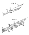
- zeigt in schematischer und perspektivischer Darstellung einen erfindungsgemäßen Stahlcord mit drei spiralförmig vorgeformten und parallel aneinanderliegenden Drahtfilamenten als Seele, die von einer Lage von sechs Hülldrähten umgeben ist.
- Figur 6
- zeigt einen weiteren erfindungsgemäßen Stahlcord mit einer Seele aus zwölf spiralförmig vorgeformten Drahtfilamenten, die von einer Lage von Hülldrähten umgeben ist, die wiederum spiralförmig mit einem Wendeldraht umgeben ist.
- Figure 1
- illustrates a schematic representation of a method according to the invention for producing a steel cord according to the invention according to FIG. 4.
- Figure 2
- illustrates a schematic representation of a method according to the invention for producing a steel cord according to the invention according to FIG. 3.
- Figure 3
- shows a schematic perspective view of a steel cord according to the invention with two spirally preformed and parallel core filaments, which are surrounded by a sheathed wire spiral.
- Figure 4
- shows a steel cord according to the invention according to Figure 3, but with six spirally preformed and parallel adjacent soul filaments.
- Figure 5
- shows a schematic and perspective view of a steel cord according to the invention with three spirally preformed and parallel adjacent wire filaments as a core, which is surrounded by a layer of six sheathed wires.
- Figure 6
- shows another steel cord according to the invention with a core of twelve spirally preformed wire filaments, which is surrounded by a layer of sheathed wires, which is in turn spirally surrounded by a helical wire.
Die Figuren 3 bis 6 zeigen verschiedene Ausführungsformen von erfindungsgemäßen
Stahlcorden mit jeweils unterschiedlicher Anzahl von
die Seele des Stahlcords bildenden Drahtfilamenten. In Figur 3 ist eine
erste Ausführungsform eines erfindungsgemäßen Stahlcords dargestellt
mit einem Drahtbündel mit zwei Seelenfilamenten 10 als Seele 60, die
spiralförmig geformt sind und parallel aneinanderliegend verlaufen. Die
beiden Seelenfilamente 10 sind von einem weiteren Filament als
Hülldraht 20 umgeben, und zwar ist der Hülldraht 20 mit der gleichen
Ganghöhe und Gangrichtung zur Spiralform der Seelenfilamente 10
gelegt. Im dargestellten Ausführungsbeispiel sind die Seelenfilamente
10 linksgängig spiralförmig geformt, und der Hülldraht 20 ist ebenfalls
linksgängig um die beiden Seelenfilamente 10 gewickelt. Die Ganghöhe
beträgt bei einem derartigen Stahlcord typischerweise etwa 14 mm,
der Durchmesser der Seelenfilamente 10 und des Hülldrahts 20 beträgt
etwa 0,28 mm.Figures 3 to 6 show different embodiments of the invention
Steel cords with different numbers of
the soul of the wire filament forming the steel cord. In Figure 3 is one
first embodiment of a steel cord according to the invention shown
with a wire bundle with two
Figur 4 zeigt eine andere Ausführungsform eines erfindungsgemäßen
Stahlcords gemäß der Figur 3, bei welchem die Seele 60 aus sechs
spiralförmig geformten und parallel aneinanderliegend verlaufenden
Seelenfilamenten 10 gebildet ist, die linksgängig spiralförmig geformt
sind und von einem siebten Filament als Hülldraht 20 linksgängig umwickelt
sind. In diesem Ausführungsbeispiel kann die Ganghöhe beispielsweise
18 mm betragen und der Durchmesser der verwendeten
Filamente 0,35 mm.Figure 4 shows another embodiment of an inventive
Steel cords according to FIG. 3, in which the
Es sind natürlich auch Stahlcorde mit Drahtbündeln denkbar, die eine noch größere Anzahl von Drahtfilamenten aufweisen. Mit zunehmender Zahl der Drahtfilamente in der Seele wird der Durchmesser der Filamente kleiner gewählt. Die Ganghöhe kann je nach Bedarf vorgegeben werden, und der Durchmesser des Hülldrahts kann gleich gewählt werden wie der Durchmesser der Drahtfilamente der Seele, kann jedoch auch von deren Durchmesser abweichen. Bei einem Seelendrahtbündel, das aus zwölf spiralförmig geformten Drahtfilamenten gebildet ist, beträgt die Ganghöhe z. B. vorteilhafterweise 12,5 mm, der Durchmesser der Drahtfilamente 0,22 mm und der Durchmesser des das Seelendrahtbündel umgebenden Hülldrahts 0,15 mm.Of course, steel cords with wire bundles are also conceivable, one have an even greater number of wire filaments. With increasing Number of wire filaments in the soul becomes the diameter of the filaments chosen smaller. The pitch can be specified as required and the diameter of the sheath wire can be chosen the same like the diameter of the wire filaments of the soul, however, can also differ from their diameter. With a bundle of soul wires, which is formed from twelve spirally shaped wire filaments the pitch z. B. advantageously 12.5 mm, the diameter the wire filaments 0.22 mm and the diameter of the bundle of soul wires surrounding sheath wire 0.15 mm.
Figur 5 zeigt ein weiteres Ausführungsbeispiel eines erfindungsgemäßen
Stahlcords in schematischer perspektivischer Darstellung. Die
Seele 60 des Stahlcords wird aus drei spiralförmig vorgeformten Seelenfilamenten
10 gebildet, die parallel aneinanderliegend verlaufen. Diese
werden von einer Lage von sechs eng aneinanderliegenden Hülldrähten
20 umgeben, die die gleiche Gangrichtung aufweisen wie die
Seelenfilamente 10. Aus Gründen der besseren Anschaulichkeit sind
die Seelenfilamente 10 länger dargestellt als die Hülldrähte 20. Die
Gangrichtung der Seelenfilamente 10 kann aber auch gegenläufig zu
der Gangrichtung der Hülldrähte 20 sein. Figure 5 shows a further embodiment of an inventive
Steel cords in a schematic perspective view. The
Eine derartige enge Umhüllung der Seele 60 mit einer Lage von Hülldrähten
20 hat den Vorteil, daß die Seelenfilamente 10 des Seelenbündels
auch bei Anwendung als Stahlgürtel nicht aus dem Seilverbund
migrieren können. Außerdem ist die Herstellung eines derartigen Stahlcords
sehr kostengünstig, da das Seelenbündel 60, wie nachfolgend
beschrieben werden wird, keinen eigenen Arbeitsgang benötigt, sondern
in Linie mit der Stahlcordherstellung produziert werden kann.Such a tight covering of the core 60 with a layer of sheathed
Bei dem in Figur 5 dargestellten Ausführungsbeispiel verfügen die
Seelenfilamente 10 vorteilhafterweise über einen Durchmesser von
0,2 mm, die Hülldrähte 20 über einen Durchmesser von 0,35 mm.In the embodiment shown in Figure 5, the
In Figur 6 ist ein dem Ausführungsbeispiel der Figur 5 ähnlicher erfindungsgemäßer
Stahlcord dargestellt, der über eine Seele 60 aus zwölf
linksgängig spiralförmig vorgeformten Seelenfilamenten 10 verfügt, die
wiederum von einer linksgängigen Lage aus fünfzehn Hülldrähten 20
umgeben sind. In diesem Ausführungsbeispiel haben alle Drähte vorteilhafterweise
denselben Durchmesser von 0,175 mm. Der in Figur 6
dargestellte Stahlcord ist darüber hinaus zusätzlich mit einem Wendeldraht
30 rechtsgängig umwickelt. Der Durchmesser des Wendeldrahts
30 beträgt beispielsweise 0,15 mm. Die Gangrichtung der Seelenfilamente
10 kann natürlich auch in diesem Ausführungsbeispiel gegenläufig
zu der Gangrichtung der Hülldrähte sein.FIG. 6 shows an embodiment of the invention which is similar to the exemplary embodiment in FIG
Steel cord shown over a
Figur 1 veranschaulicht in schematischer Darstellung ein erfindungsgemäßes
Verfahren zur Herstellung eines in Figur 4 dargestellten erfindungsgemäßen
Stahlcords. Zur Herstellung dieses Stahlcords mit einem
Seelenbündel aus sechs Drahtfilamenten werden in einem ersten
Arbeitsschritt A die Seelenfilamente 10 von sechs Spulen 11 abgezogen.
In einem weiteren Arbeitsschritt B werden jeweils drei der sechs
Seelenfilamente 10 mittels Umlenkrollen 15 zu einem Strang 50 zusammengefaßt,
um anschließend in einem dritten Arbeitsschritt C von
zwei Falschdrallern 40 jeweils rechtsgängig mit einer eingestellten
Ganghöhe (hier: 18 mm) spiralförmig vorgeformt zu werden. Nach dem
Verlassen der Falschdraller 40 werden die beiden Bündel mit jeweils
drei Seelenfilamenten in einem weiteren Arbeitsschritt D mittels Umlenkrollen
15 zu einem Drahtbündel aus sechs Drahtfilamenten zusammengesetzt,
das die Seele 60 des herzustellenden Stahlcords bildet.
Die Seele 60 aus sechs Seelenfilamenten 10, die rechtsgängig spiralförmig
geformt sind, wird im gleichen Arbeitsgang mit einem Hülldraht
20 umgeben, der im Arbeitsschritt E von einer Spule 21 abgezogen
und im Arbeitsschritt F rechtsgängig mit einer vorgegebenen Ganghöhe
(beispielsweise 18 mm) um die Seele 60 gewickelt wird. Das Resultat
dieses Herstellungsverfahrens ist ein erfindungsgemäßer Stahlcord, wie
er in Figur 4 dargestellt ist, wobei der in Figur 4 dargestellte Stahlcord
ebenso wie der in Figur 3 dargestellte Stahlcord über linksgängige
Seelenfilamente 10 und Hülldrähte 20 verfügt.Figure 1 illustrates a schematic representation of an inventive
Process for producing an inventive device shown in FIG
Steel cords. To make this steel cord with a
Bundles of six wire filaments are used in a first
Step A, the
Die in diesem Herstellungsverfahren verwendeten als Seelenfilamente Drahtfilamente sind vorteilhafterweise aus Walzdraht einer Stahlqualität von 0,6 bis 0,9 % C, 0,4 bis 0,8 % Mn und 0,1 bis 0,3 % Si sowie maximal 0,03 % S, P und weiteren üblichen Begleitelementen. Der Walzdraht wird im Vorfeld in mehreren Stufen von 5,5 mm auf dünnere Durchmesser gewalzt, gezogen, wärmebehandelt und vor der anschließenden, letzten Stufe, meistens eine Naßziehstufe, vermessingt. Das Messing wird als "Schmiermittel" beim Ziehen ausgenutzt, dient jedoch primär der Haftung des Stahlcords mit der Gummimischung des Reifens. Die Herstellung der Stahlcorde erfolgt durch Verdrillung und Verseilung der Drahtfilamente in geeigneter Anzahl und Form, wobei bei der Wahl der Maschinenparameter eine geeignete Kombination von Spulengröße und Maschinenumdrehungszahl gefunden werden muß, da eine hohe Umdrehungszahl mit kleinen Einsatzspulen und entsprechend eine niedrige Umdrehungszahl mit großen Einsatzspulen verbunden ist.The wire filaments used as core filaments in this manufacturing process are advantageously made of wire rod with a steel quality of 0.6 to 0.9% C, 0.4 to 0.8% Mn and 0.1 to 0.3% Si and a maximum of 0.03% S, P and other usual accompanying elements. The wire rod is in advance rolled in several steps from 5.5 mm to thinner diameters, drawn, heat-treated and before the subsequent, final stage, mostly a wet drawing step, brassed. The brass is called "Lubricant" used when pulling, but primarily serves as liability of the steel cord with the rubber compound of the tire. The production the steel cords are made by twisting and stranding the Wire filaments in a suitable number and shape, with the choice of Machine parameters a suitable combination of coil size and Engine speed must be found because of a high speed with small insert coils and accordingly a low one Speed is connected with large insert coils.
Das dargestellte erfindungsgemäße Verfahren zur Herstellung eines Stahlcords eignet sich zur Herstellung von Stahlcorden mit Seelenbündeln aus zwei bis zu dreißig Drahtfilamenten, wobei auch Cordkonstruktionen gleicher Art mit mehr als dreißig Drahtfilamenten vorstellbar sind.The method according to the invention for producing a Steel cords are suitable for the production of steel cords with bundles of souls from two to thirty wire filaments, including cord constructions same type imaginable with more than thirty wire filaments are.
Figur 2 veranschaulicht ein Verfahren zur Herstellung eines erfindungsgemäßen
Stahlcords, wie er in Figur 3 dargestellt ist. In einem ersten
Arbeitsschritt A werden zwei Seelenfilamente 10 von zwei Spulen 11
abgezogen und in einem zweiten Arbeitsschritt B zusammengeführt.
Die beiden Seelenfilamente 10 werden in einem weiteren Arbeitsschritt
C in einem Falschdraller 40 rechtsgängig mit einer eingestellten Ganghöhe
(beispielsweise 14 mm) rechtsgängig spiralförmig geformt. Diese
beiden spiralförmig umeinander verdrehten Seelenfilamente 10 bilden die
Seele 60 des herzustellenden Stahlcords. In einem nächsten Arbeitsschritt
E wird ein Drahtfilament von einer Spule 21 abgezogen,
welches als Hülldraht 20 in einem letzten Arbeitsschritt F um die Seele
60 rechtsgängig mit einer Ganghöhe von beispielsweise 14 mm gewikkelt
wird.Figure 2 illustrates a method for producing an inventive
Steel cords as shown in Figure 3. In a first
Step A becomes two
In weiterer Ausgestaltung der Erfindung werden die vorstehend beschriebenen erfindungsgemäßen Stahlcorde in eine ovale Form gedrückt. Dies eignet sich insbesondere bei Stahlcorden wie sie in den Figuren 5 und 6 dargestellt sind. Die ovale Form des Stahlcords kann beispielsweise durch Zusammendrücken des Cords mittels eines Rollenpaares erhalten werden. Auf Grund der unterschiedlichen Steifigkeit in radialer und lateraler Richtung hat die ovale Form des Stahlcords für eine Anwendung im Reifen erhebliche Vorteile.In a further embodiment of the invention, those described above are described Steel cords according to the invention pressed into an oval shape. This is particularly suitable for steel cords as in the Figures 5 and 6 are shown. The oval shape of the steel cord can for example by pressing the cord together using a pair of rollers be preserved. Due to the different stiffness in the radial and lateral direction the oval shape of the steel cord has an application in tires has considerable advantages.
Der vorgeschlagene erfindungsgemäße Stahlcord ist einfach und kostengünstig herstellbar und zeichnet sich durch hervorragende Eigenschaften, insbesondere bei Stauchbeanspruchung aus. Er läßt sich leicht gummieren, da die Resttorsionsspannungen nach außen hin aufgehoben sind und er somit beim Gummierungsvorgang flach liegen bleibt. Auch ist die Migrationsfähigkeit der verwendeten Drahtfilamente aus dem Seilverbund bei Verwendung als Gürtel sehr gering. Mit der erfindungsgemäß vorgeschlagenen Ausgestaltung sind eine Vielzahl von Stahlcord-Konstruktionen herstellbar, die einen weiten Anwendungsbereich abdecken, angefangen bei Stahlcorden für den Pkw-Reifen über Leicht-Lkw-Reifen bis zum Lkw- und Busreifen.The proposed steel cord according to the invention is simple and inexpensive producible and is characterized by excellent properties, especially in the case of compressive stress. He lets himself rubberize slightly, as the residual torsional stresses are released to the outside are and thus lie flat during the gumming process remains. The migration ability of the wire filaments used is also great from the rope assembly when used as a belt very low. With the A variety of configurations proposed according to the invention are numerous of steel cord constructions that can be used in a wide range of applications cover, starting with steel cords for car tires from light truck tires to truck and bus tires.
Claims (18)
- A process of producing a steel cord characterized by the following steps:A:uncoiling from reels (11) at least two wire filaments serving as core filaments (10),B:combining said uncoiled core filaments (10) in a false twister (40) into a strand (50) and initially intertwining the core filaments to spirally preshape them,C: sheathing said spirally preshaped individual filaments (10) located downstream of said false twister (40) juxtaposed in parallel in the form of a core (60) with at least one wire filament serving as the sheathing wire (60) uncoiled from a reel (21).
- The process as set forth in claim 1, characterized in that in step B two, three or four core filaments (10) are mutually intertwined and in that two or more stands (50) incorporating two, three or four intertwined core filaments (10) are combined into a core (60) in an additional step C.
- The process as set forth in claim 1 or 2, characterized in that said at least two core filaments (10) are intertwined left-handedly or right-handedly and in that at said least one sheathing wire (20) is likewise wound left-handedly or right-handedly about said preshaped core filaments (10).
- A process for producing a steel cord, characterized in that a steel cord produced as set forth in any of the claims 1 to 3 is compressed such that it receives an oval shape.
- The process as set forth in claim 4, characterized in that said steel cord is compressed into an oval shape through a pair of rolls.
- A steel cord produced by a process as set forth in any of the -claims 1 to 5.
- The steel cord as set forth in claim 6, characterized in that at said least two core filaments (10) are shaped as right-handed or left-handed spirals and said at least one sheathing wire (20) surrounding said at least two core filaments (10) likewise right-handedly or left-handedly.
- The steel cord as set forth in claim 6 or 7, characterized in that the pitch of the spiral preshape of said core filaments (10) corresponds to the pitch of said sheathing wire (20) surrounding the latter.
- The steel cord as set forth in any of the claims 6 to 8, characterized in that the pitch of said preshape and the pitch of said surrounding sheathing wire (20) is between 6 mm and 30 mm.
- The steel cord as set forth in any of the claims 6 to 9, characterized in that the outer diameter of the spirals of each preshaped core filament (10) is between 0.1 and 0.5 mm.
- The steel cord as set forth in any of the claims 6 to 10, characterized in that the diameter of said core filaments (10) is between 0.12 and 0.5 mm.
- The steel cord as set forth in any of the claims 6 to 11, characterized in that one or more plies of sheathing wires (20) are provided surrounding said at least two core filaments (10).
- The steel cord as set forth in any of the claims 6 to 12, characterized in that said core filaments (10) and said sheathing wires (20) are the same in diameter.
- The steel cord as set forth in any of the claims 6 to 12, characterized in that said core filaments (10) and said sheathing wires (20) differ in diameter.
- The steel cord as set forth in any of the claims 6 to 14, characterized in that a spiral wire (20) surrounding said sheathing wires (20) is provided.
- The steel cord as set forth in any of the claims 6 to 15, characterized in that at least two wire filaments as core filaments (10) forming a core (60) are oriented bunched juxtaposed in parallel and feature elastic residual torsional stresses which are cancelled in conjunction with the restoring forces of at least one sheathing wire (20) surrounding the core filaments (10).
- The steel cord as set forth in any of the claims 6 to 16, characterized in that said steel cord features a flattened, substantially oval shape.
- The steel cord as set forth in claim 17, characterized in that the ratio of width to height of said flattened steel cord is 1.15 to 1.50.
Applications Claiming Priority (3)
| Application Number | Priority Date | Filing Date | Title |
|---|---|---|---|
| DE19535598 | 1995-09-25 | ||
| DE19535598A DE19535598A1 (en) | 1995-09-25 | 1995-09-25 | Method of making a steel cord |
| PCT/EP1996/003884 WO1997012091A1 (en) | 1995-09-25 | 1996-09-04 | Process for producing a steel cord |
Publications (2)
| Publication Number | Publication Date |
|---|---|
| EP0852634A1 EP0852634A1 (en) | 1998-07-15 |
| EP0852634B1 true EP0852634B1 (en) | 1999-12-08 |
Family
ID=7773114
Family Applications (1)
| Application Number | Title | Priority Date | Filing Date |
|---|---|---|---|
| EP96931018A Expired - Lifetime EP0852634B1 (en) | 1995-09-25 | 1996-09-04 | Process for producing a steel cord |
Country Status (15)
| Country | Link |
|---|---|
| US (1) | US6076344A (en) |
| EP (1) | EP0852634B1 (en) |
| JP (1) | JPH11512787A (en) |
| KR (1) | KR100434750B1 (en) |
| CN (1) | CN1079864C (en) |
| AT (1) | ATE187512T1 (en) |
| BR (1) | BR9610722A (en) |
| CA (1) | CA2232549A1 (en) |
| CZ (1) | CZ294724B6 (en) |
| DE (2) | DE19535598A1 (en) |
| ES (1) | ES2142610T3 (en) |
| RU (1) | RU2151227C1 (en) |
| SK (1) | SK284783B6 (en) |
| TR (1) | TR199800542T2 (en) |
| WO (1) | WO1997012091A1 (en) |
Families Citing this family (19)
| Publication number | Priority date | Publication date | Assignee | Title |
|---|---|---|---|---|
| DE19912192C2 (en) * | 1999-03-18 | 2001-03-08 | Drahtcord Saar Gmbh & Co Kg | False twist and method, in particular for producing spiral filaments |
| EP1167620A1 (en) * | 2000-06-19 | 2002-01-02 | DRAHTCORD SAAR GMBH & Co.KG | Steel cord |
| JP2002294573A (en) * | 2001-03-30 | 2002-10-09 | Tokusen Kogyo Co Ltd | Steel cord for tire reinforcement and tire |
| PL206484B1 (en) * | 2001-04-26 | 2010-08-31 | Bekaert Sa Nv | Steel cord for reinforcing rubber articles |
| US20050034443A1 (en) * | 2003-08-14 | 2005-02-17 | Cook Thomas Christopher | Optical fibers twinning apparatus and process |
| US7901870B1 (en) | 2004-05-12 | 2011-03-08 | Cirrex Systems Llc | Adjusting optical properties of optical thin films |
| US7565084B1 (en) | 2004-09-15 | 2009-07-21 | Wach Michael L | Robustly stabilizing laser systems |
| JP5319219B2 (en) * | 2008-09-16 | 2013-10-16 | 株式会社ブリヂストン | Code manufacturing apparatus and code manufacturing method |
| CN103459292B (en) * | 2011-04-14 | 2016-12-07 | 奥的斯电梯公司 | Rope or belt for the coating of elevator device |
| JP5825234B2 (en) * | 2012-09-11 | 2015-12-02 | 横浜ゴム株式会社 | Steel cord and conveyor belt for rubber reinforcement |
| FR3028872B1 (en) * | 2014-11-25 | 2017-05-19 | Michelin & Cie | FRACTIONATION METHOD |
| FR3028873B1 (en) * | 2014-11-25 | 2016-12-23 | Michelin & Cie | FRACTIONAL INSTALLATION |
| CN104631167B (en) * | 2015-02-11 | 2017-03-01 | 辽宁通达建材实业有限公司 | Low consumption prestress wire production technology |
| CN107044060B (en) * | 2017-05-31 | 2022-10-14 | 东华大学 | Twisting and plying method and equipment for continuous superfine metal filament |
| CN109338766A (en) * | 2018-11-10 | 2019-02-15 | 江苏兴达钢帘线股份有限公司 | 1 × n of one kind × d series radial tires steel cord production method |
| CN110373922B (en) * | 2019-05-22 | 2022-07-29 | 东台磊达钢帘线有限公司 | Production equipment and production method of steel cord |
| FR3099192A1 (en) * | 2019-07-25 | 2021-01-29 | Compagnie Generale Des Etablissements Michelin | Process for splitting and reassembling a two-layer assembly |
| US11598027B2 (en) * | 2019-12-18 | 2023-03-07 | Patrick Yarn Mills, Inc. | Methods and systems for forming a composite yarn |
| CN113403870A (en) * | 2021-06-25 | 2021-09-17 | 山东大业股份有限公司 | Ultrahigh-strength high-rubber-permeability steel cord, twisting method and twisting equipment |
Family Cites Families (14)
| Publication number | Priority date | Publication date | Assignee | Title |
|---|---|---|---|---|
| FR2260660B1 (en) * | 1974-02-12 | 1976-11-26 | Michelin & Cie | |
| IT1059752B (en) * | 1975-05-12 | 1982-06-21 | Akzo Nv | REINFORCEMENT CABLE FOR ELASTOMERIC TICLES AND RELATED METHOD AND MANUFACTURING APPARATUS |
| GB1582647A (en) * | 1977-07-07 | 1981-01-14 | Bekaert Sa Nv | Metal cord |
| US4545190A (en) * | 1983-09-26 | 1985-10-08 | The Goodyear Tire & Rubber Company | Metallic cable and method and apparatus for making same |
| EP0168858B1 (en) * | 1984-07-09 | 1989-05-31 | N.V. Bekaert S.A. | Compact steel cord for improved tensile strength |
| GB8424086D0 (en) * | 1984-09-24 | 1984-10-31 | Bekaert Sa Nv | Steel cord |
| DE3635298A1 (en) * | 1986-10-16 | 1988-04-21 | Akzo Gmbh | TIRES WITH FLAT CORDS OR FLAT CORD |
| AT391292B (en) * | 1987-12-18 | 1990-09-10 | Miller Martin Ag | METHOD FOR PRODUCING A SINGLE OR TWO-SIDED PUNCHING KNIFE FOR NON-METAL MATERIALS |
| JPH02104783A (en) * | 1988-10-11 | 1990-04-17 | Kanai Hiroyuki | Steel cord and tire |
| JP2936112B2 (en) * | 1988-11-11 | 1999-08-23 | 株式会社ブリヂストン | Steel cord for reinforcement |
| US5323596A (en) * | 1990-11-05 | 1994-06-28 | The Goodyear Tire & Rubber Company | Open metallic cord for penetration by elastomer |
| US5198307A (en) * | 1990-12-21 | 1993-03-30 | N. V. Bekaert S.A. | Steel strip and method of making |
| US5581990A (en) * | 1994-04-07 | 1996-12-10 | N.V. Bekaert S.A. | Twisting steel cord with wavy filament |
| IT1277689B1 (en) * | 1995-12-21 | 1997-11-11 | Pirelli | METALLIC STRENGTHENING CORD TO BE USED PARTICULARLY IN COMPOSITE ELASTOMERIC MATRIX PRODUCTS PROCEDURE AND APPARATUS |
-
1995
- 1995-09-25 DE DE19535598A patent/DE19535598A1/en not_active Withdrawn
-
1996
- 1996-09-04 SK SK369-98A patent/SK284783B6/en not_active IP Right Cessation
- 1996-09-04 BR BR9610722A patent/BR9610722A/en not_active IP Right Cessation
- 1996-09-04 CZ CZ1998892A patent/CZ294724B6/en not_active IP Right Cessation
- 1996-09-04 JP JP9513103A patent/JPH11512787A/en active Pending
- 1996-09-04 ES ES96931018T patent/ES2142610T3/en not_active Expired - Lifetime
- 1996-09-04 DE DE59603883T patent/DE59603883D1/en not_active Expired - Lifetime
- 1996-09-04 EP EP96931018A patent/EP0852634B1/en not_active Expired - Lifetime
- 1996-09-04 WO PCT/EP1996/003884 patent/WO1997012091A1/en active IP Right Grant
- 1996-09-04 RU RU98107841/02A patent/RU2151227C1/en not_active IP Right Cessation
- 1996-09-04 TR TR1998/00542T patent/TR199800542T2/en unknown
- 1996-09-04 AT AT96931018T patent/ATE187512T1/en not_active IP Right Cessation
- 1996-09-04 KR KR10-1998-0702170A patent/KR100434750B1/en not_active IP Right Cessation
- 1996-09-04 CA CA002232549A patent/CA2232549A1/en not_active Abandoned
- 1996-09-04 US US09/043,500 patent/US6076344A/en not_active Expired - Lifetime
- 1996-09-04 CN CN96198549A patent/CN1079864C/en not_active Expired - Fee Related
Also Published As
| Publication number | Publication date |
|---|---|
| BR9610722A (en) | 1999-07-13 |
| ATE187512T1 (en) | 1999-12-15 |
| SK284783B6 (en) | 2005-11-03 |
| CN1079864C (en) | 2002-02-27 |
| WO1997012091A1 (en) | 1997-04-03 |
| CA2232549A1 (en) | 1997-04-03 |
| EP0852634A1 (en) | 1998-07-15 |
| US6076344A (en) | 2000-06-20 |
| CZ89298A3 (en) | 1998-07-15 |
| DE59603883D1 (en) | 2000-01-13 |
| CZ294724B6 (en) | 2005-03-16 |
| KR19990063703A (en) | 1999-07-26 |
| DE19535598A1 (en) | 1997-03-27 |
| SK36998A3 (en) | 2000-02-14 |
| JPH11512787A (en) | 1999-11-02 |
| RU2151227C1 (en) | 2000-06-20 |
| TR199800542T2 (en) | 1998-07-21 |
| ES2142610T3 (en) | 2000-04-16 |
| CN1202942A (en) | 1998-12-23 |
| KR100434750B1 (en) | 2004-09-04 |
Similar Documents
| Publication | Publication Date | Title |
|---|---|---|
| EP0852634B1 (en) | Process for producing a steel cord | |
| EP0125518B1 (en) | Cord for the reinforcement of elastomers | |
| DE2619086C2 (en) | Reinforcement rope for elastomer products, method and apparatus for manufacture | |
| DE60017978T2 (en) | Steel rope for reinforcing rubber articles, and method and apparatus for producing such steel cables | |
| EP0126965B1 (en) | Reinforcement cord made of at least two components | |
| EP2289072B1 (en) | Method for producing a braid, and also a braid comprising a plurality of wires | |
| DE3047365A1 (en) | THROUGH RADIAL TIRES REINFORCED BY STEEL CORD | |
| DE3215638A1 (en) | STEEL ROPE FOR REINFORCING ELASTOMER MATERIAL | |
| EP0125517A2 (en) | Reinforcement cord with lapping wire | |
| DE60121671T2 (en) | Wire rope for motor vehicle window lifter | |
| DE7936995U1 (en) | CONNECTING STRAND MADE OF RUBBER OR RUBBER-LIKE MATERIAL OR PLASTIC WITH REINFORCEMENT | |
| DE69726052T2 (en) | Steel cord with several strands | |
| DE3516220C2 (en) | Pneumatic tire in radial design | |
| DE2044665A1 (en) | ||
| EP0852635B1 (en) | Wire filament, especially for reinforcing rubber of plastic items, process for its production and device for implementing the process | |
| CH688915A5 (en) | Steel wire rope. | |
| DE4409182A1 (en) | Strength members for vehicle tires | |
| EP1815061A1 (en) | Strand with increased adherence to metal disks | |
| DE60212367T2 (en) | STEEL ROPE FOR REINFORCING RUBBER ARTICLES | |
| EP0164065B1 (en) | Method for manufacturing a compact single-strand-reinforcing cord with plural layers for elastomeric articles, and reinforcing cord made by this method | |
| DE3215986C2 (en) | ||
| DE112018007311T5 (en) | ELEVATOR ROPE | |
| DE102017205014B4 (en) | Bunching machine, method of making a strand and strand | |
| LU84845A1 (en) | METAL WIRE ROPE FOR REINFORCING ELASTOMERIC PRODUCTS | |
| DE2851664C2 (en) | Process for the production of stranded wire products |
Legal Events
| Date | Code | Title | Description |
|---|---|---|---|
| PUAI | Public reference made under article 153(3) epc to a published international application that has entered the european phase |
Free format text: ORIGINAL CODE: 0009012 |
|
| 17P | Request for examination filed |
Effective date: 19980424 |
|
| AK | Designated contracting states |
Kind code of ref document: A1 Designated state(s): AT BE DE ES FR GB IT LU |
|
| GRAG | Despatch of communication of intention to grant |
Free format text: ORIGINAL CODE: EPIDOS AGRA |
|
| 17Q | First examination report despatched |
Effective date: 19990114 |
|
| GRAG | Despatch of communication of intention to grant |
Free format text: ORIGINAL CODE: EPIDOS AGRA |
|
| GRAH | Despatch of communication of intention to grant a patent |
Free format text: ORIGINAL CODE: EPIDOS IGRA |
|
| GRAH | Despatch of communication of intention to grant a patent |
Free format text: ORIGINAL CODE: EPIDOS IGRA |
|
| GRAA | (expected) grant |
Free format text: ORIGINAL CODE: 0009210 |
|
| AK | Designated contracting states |
Kind code of ref document: B1 Designated state(s): AT BE DE ES FR GB IT LU |
|
| REF | Corresponds to: |
Ref document number: 187512 Country of ref document: AT Date of ref document: 19991215 Kind code of ref document: T |
|
| REF | Corresponds to: |
Ref document number: 59603883 Country of ref document: DE Date of ref document: 20000113 |
|
| ITF | It: translation for a ep patent filed |
Owner name: PORTA CHECCACCI & ASSOCIATI S.P.A. |
|
| ET | Fr: translation filed | ||
| GBT | Gb: translation of ep patent filed (gb section 77(6)(a)/1977) |
Effective date: 20000222 |
|
| REG | Reference to a national code |
Ref country code: ES Ref legal event code: FG2A Ref document number: 2142610 Country of ref document: ES Kind code of ref document: T3 |
|
| PLBE | No opposition filed within time limit |
Free format text: ORIGINAL CODE: 0009261 |
|
| STAA | Information on the status of an ep patent application or granted ep patent |
Free format text: STATUS: NO OPPOSITION FILED WITHIN TIME LIMIT |
|
| 26N | No opposition filed | ||
| PGFP | Annual fee paid to national office [announced via postgrant information from national office to epo] |
Ref country code: GB Payment date: 20010814 Year of fee payment: 6 |
|
| PGFP | Annual fee paid to national office [announced via postgrant information from national office to epo] |
Ref country code: AT Payment date: 20010921 Year of fee payment: 6 |
|
| REG | Reference to a national code |
Ref country code: GB Ref legal event code: IF02 |
|
| PG25 | Lapsed in a contracting state [announced via postgrant information from national office to epo] |
Ref country code: GB Free format text: LAPSE BECAUSE OF NON-PAYMENT OF DUE FEES Effective date: 20020904 Ref country code: AT Free format text: LAPSE BECAUSE OF NON-PAYMENT OF DUE FEES Effective date: 20020904 |
|
| GBPC | Gb: european patent ceased through non-payment of renewal fee |
Effective date: 20020904 |
|
| PGFP | Annual fee paid to national office [announced via postgrant information from national office to epo] |
Ref country code: ES Payment date: 20050927 Year of fee payment: 10 |
|
| PGFP | Annual fee paid to national office [announced via postgrant information from national office to epo] |
Ref country code: BE Payment date: 20060922 Year of fee payment: 11 |
|
| PGFP | Annual fee paid to national office [announced via postgrant information from national office to epo] |
Ref country code: LU Payment date: 20060927 Year of fee payment: 11 |
|
| BERE | Be: lapsed |
Owner name: *DRAHTCORD SAAR G.M.B.H. & CO. K.G. Effective date: 20070930 |
|
| PG25 | Lapsed in a contracting state [announced via postgrant information from national office to epo] |
Ref country code: BE Free format text: LAPSE BECAUSE OF NON-PAYMENT OF DUE FEES Effective date: 20070930 |
|
| REG | Reference to a national code |
Ref country code: ES Ref legal event code: FD2A Effective date: 20070905 |
|
| PG25 | Lapsed in a contracting state [announced via postgrant information from national office to epo] |
Ref country code: ES Free format text: LAPSE BECAUSE OF NON-PAYMENT OF DUE FEES Effective date: 20070905 |
|
| PG25 | Lapsed in a contracting state [announced via postgrant information from national office to epo] |
Ref country code: LU Free format text: LAPSE BECAUSE OF NON-PAYMENT OF DUE FEES Effective date: 20070904 |
|
| PGFP | Annual fee paid to national office [announced via postgrant information from national office to epo] |
Ref country code: IT Payment date: 20120926 Year of fee payment: 17 Ref country code: DE Payment date: 20120928 Year of fee payment: 17 |
|
| PGFP | Annual fee paid to national office [announced via postgrant information from national office to epo] |
Ref country code: FR Payment date: 20121008 Year of fee payment: 17 |
|
| REG | Reference to a national code |
Ref country code: DE Ref legal event code: R119 Ref document number: 59603883 Country of ref document: DE Effective date: 20140401 |
|
| REG | Reference to a national code |
Ref country code: FR Ref legal event code: ST Effective date: 20140530 |
|
| PG25 | Lapsed in a contracting state [announced via postgrant information from national office to epo] |
Ref country code: DE Free format text: LAPSE BECAUSE OF NON-PAYMENT OF DUE FEES Effective date: 20140401 Ref country code: FR Free format text: LAPSE BECAUSE OF NON-PAYMENT OF DUE FEES Effective date: 20130930 Ref country code: IT Free format text: LAPSE BECAUSE OF NON-PAYMENT OF DUE FEES Effective date: 20130904 |