EP0851997B1 - Procedure and device for drying a coated substrate - Google Patents
Procedure and device for drying a coated substrate Download PDFInfo
- Publication number
- EP0851997B1 EP0851997B1 EP96930780A EP96930780A EP0851997B1 EP 0851997 B1 EP0851997 B1 EP 0851997B1 EP 96930780 A EP96930780 A EP 96930780A EP 96930780 A EP96930780 A EP 96930780A EP 0851997 B1 EP0851997 B1 EP 0851997B1
- Authority
- EP
- European Patent Office
- Prior art keywords
- substrate
- condensing
- condensing surface
- condensate
- drying
- Prior art date
- Legal status (The legal status is an assumption and is not a legal conclusion. Google has not performed a legal analysis and makes no representation as to the accuracy of the status listed.)
- Expired - Lifetime
Links
- 238000001035 drying Methods 0.000 title claims description 97
- 239000000758 substrate Substances 0.000 title claims description 67
- 238000000034 method Methods 0.000 title claims description 35
- 239000007788 liquid Substances 0.000 claims description 94
- 230000005484 gravity Effects 0.000 claims description 20
- 239000000463 material Substances 0.000 claims description 16
- 238000012546 transfer Methods 0.000 claims description 8
- 238000001704 evaporation Methods 0.000 claims description 6
- 238000000576 coating method Methods 0.000 description 46
- 239000011248 coating agent Substances 0.000 description 39
- 239000007789 gas Substances 0.000 description 32
- 239000002904 solvent Substances 0.000 description 29
- 238000009833 condensation Methods 0.000 description 12
- 230000005494 condensation Effects 0.000 description 12
- 238000010438 heat treatment Methods 0.000 description 12
- 239000002245 particle Substances 0.000 description 10
- 230000008901 benefit Effects 0.000 description 8
- 230000007547 defect Effects 0.000 description 8
- 238000011084 recovery Methods 0.000 description 8
- 230000008569 process Effects 0.000 description 7
- 239000003570 air Substances 0.000 description 6
- 239000012530 fluid Substances 0.000 description 5
- 230000005499 meniscus Effects 0.000 description 5
- XLYOFNOQVPJJNP-UHFFFAOYSA-N water Substances O XLYOFNOQVPJJNP-UHFFFAOYSA-N 0.000 description 5
- 230000015572 biosynthetic process Effects 0.000 description 4
- 230000002829 reductive effect Effects 0.000 description 4
- 239000007787 solid Substances 0.000 description 4
- 239000012080 ambient air Substances 0.000 description 3
- 238000009792 diffusion process Methods 0.000 description 3
- 230000008020 evaporation Effects 0.000 description 3
- 239000013529 heat transfer fluid Substances 0.000 description 3
- 230000007246 mechanism Effects 0.000 description 3
- 229920000642 polymer Polymers 0.000 description 3
- 230000005855 radiation Effects 0.000 description 3
- 238000001311 chemical methods and process Methods 0.000 description 2
- 238000006243 chemical reaction Methods 0.000 description 2
- 230000000694 effects Effects 0.000 description 2
- 238000005516 engineering process Methods 0.000 description 2
- 239000002184 metal Substances 0.000 description 2
- 239000003960 organic solvent Substances 0.000 description 2
- 239000000123 paper Substances 0.000 description 2
- 230000000704 physical effect Effects 0.000 description 2
- 230000000717 retained effect Effects 0.000 description 2
- 230000003068 static effect Effects 0.000 description 2
- 239000004819 Drying adhesive Substances 0.000 description 1
- 241000364021 Tulsa Species 0.000 description 1
- 230000002411 adverse Effects 0.000 description 1
- 238000013459 approach Methods 0.000 description 1
- QVGXLLKOCUKJST-UHFFFAOYSA-N atomic oxygen Chemical compound [O] QVGXLLKOCUKJST-UHFFFAOYSA-N 0.000 description 1
- 230000004888 barrier function Effects 0.000 description 1
- 238000001816 cooling Methods 0.000 description 1
- 238000013500 data storage Methods 0.000 description 1
- 238000002474 experimental method Methods 0.000 description 1
- 239000007888 film coating Substances 0.000 description 1
- 238000009501 film coating Methods 0.000 description 1
- 238000005188 flotation Methods 0.000 description 1
- 230000002706 hydrostatic effect Effects 0.000 description 1
- 239000011261 inert gas Substances 0.000 description 1
- 230000000670 limiting effect Effects 0.000 description 1
- 239000006249 magnetic particle Substances 0.000 description 1
- 238000004519 manufacturing process Methods 0.000 description 1
- 239000000203 mixture Substances 0.000 description 1
- 230000004048 modification Effects 0.000 description 1
- 238000012986 modification Methods 0.000 description 1
- 231100000252 nontoxic Toxicity 0.000 description 1
- 230000003000 nontoxic effect Effects 0.000 description 1
- 239000001301 oxygen Substances 0.000 description 1
- 229910052760 oxygen Inorganic materials 0.000 description 1
- 238000005086 pumping Methods 0.000 description 1
- 239000000376 reactant Substances 0.000 description 1
- 239000013557 residual solvent Substances 0.000 description 1
- 230000002441 reversible effect Effects 0.000 description 1
- 229920006395 saturated elastomer Polymers 0.000 description 1
- 238000007790 scraping Methods 0.000 description 1
- 238000001179 sorption measurement Methods 0.000 description 1
- 239000000126 substance Substances 0.000 description 1
- 239000011800 void material Substances 0.000 description 1
Images


Classifications
-
- F—MECHANICAL ENGINEERING; LIGHTING; HEATING; WEAPONS; BLASTING
- F26—DRYING
- F26B—DRYING SOLID MATERIALS OR OBJECTS BY REMOVING LIQUID THEREFROM
- F26B25/00—Details of general application not covered by group F26B21/00 or F26B23/00
- F26B25/005—Treatment of dryer exhaust gases
- F26B25/006—Separating volatiles, e.g. recovering solvents from dryer exhaust gases
-
- F—MECHANICAL ENGINEERING; LIGHTING; HEATING; WEAPONS; BLASTING
- F26—DRYING
- F26B—DRYING SOLID MATERIALS OR OBJECTS BY REMOVING LIQUID THEREFROM
- F26B13/00—Machines and apparatus for drying fabrics, fibres, yarns, or other materials in long lengths, with progressive movement
- F26B13/10—Arrangements for feeding, heating or supporting materials; Controlling movement, tension or position of materials
-
- F—MECHANICAL ENGINEERING; LIGHTING; HEATING; WEAPONS; BLASTING
- F26—DRYING
- F26B—DRYING SOLID MATERIALS OR OBJECTS BY REMOVING LIQUID THEREFROM
- F26B13/00—Machines and apparatus for drying fabrics, fibres, yarns, or other materials in long lengths, with progressive movement
- F26B13/10—Arrangements for feeding, heating or supporting materials; Controlling movement, tension or position of materials
- F26B13/105—Drying webs by contact with heated surfaces other than rollers or drums
-
- F—MECHANICAL ENGINEERING; LIGHTING; HEATING; WEAPONS; BLASTING
- F26—DRYING
- F26B—DRYING SOLID MATERIALS OR OBJECTS BY REMOVING LIQUID THEREFROM
- F26B25/00—Details of general application not covered by group F26B21/00 or F26B23/00
-
- F—MECHANICAL ENGINEERING; LIGHTING; HEATING; WEAPONS; BLASTING
- F26—DRYING
- F26B—DRYING SOLID MATERIALS OR OBJECTS BY REMOVING LIQUID THEREFROM
- F26B3/00—Drying solid materials or objects by processes involving the application of heat
- F26B3/18—Drying solid materials or objects by processes involving the application of heat by conduction, i.e. the heat is conveyed from the heat source, e.g. gas flame, to the materials or objects to be dried by direct contact
- F26B3/20—Drying solid materials or objects by processes involving the application of heat by conduction, i.e. the heat is conveyed from the heat source, e.g. gas flame, to the materials or objects to be dried by direct contact the heat source being a heated surface, e.g. a moving belt or conveyor
-
- F—MECHANICAL ENGINEERING; LIGHTING; HEATING; WEAPONS; BLASTING
- F26—DRYING
- F26B—DRYING SOLID MATERIALS OR OBJECTS BY REMOVING LIQUID THEREFROM
- F26B7/00—Drying solid materials or objects by processes using a combination of processes not covered by a single one of groups F26B3/00 and F26B5/00
- F26B7/002—Drying solid materials or objects by processes using a combination of processes not covered by a single one of groups F26B3/00 and F26B5/00 using an electric field and heat
-
- G—PHYSICS
- G11—INFORMATION STORAGE
- G11B—INFORMATION STORAGE BASED ON RELATIVE MOVEMENT BETWEEN RECORD CARRIER AND TRANSDUCER
- G11B5/00—Recording by magnetisation or demagnetisation of a record carrier; Reproducing by magnetic means; Record carriers therefor
- G11B5/84—Processes or apparatus specially adapted for manufacturing record carriers
-
- G—PHYSICS
- G11—INFORMATION STORAGE
- G11B—INFORMATION STORAGE BASED ON RELATIVE MOVEMENT BETWEEN RECORD CARRIER AND TRANSDUCER
- G11B5/00—Recording by magnetisation or demagnetisation of a record carrier; Reproducing by magnetic means; Record carriers therefor
- G11B5/84—Processes or apparatus specially adapted for manufacturing record carriers
- G11B5/842—Coating a support with a liquid magnetic dispersion
-
- G—PHYSICS
- G11—INFORMATION STORAGE
- G11B—INFORMATION STORAGE BASED ON RELATIVE MOVEMENT BETWEEN RECORD CARRIER AND TRANSDUCER
- G11B5/00—Recording by magnetisation or demagnetisation of a record carrier; Reproducing by magnetic means; Record carriers therefor
- G11B5/84—Processes or apparatus specially adapted for manufacturing record carriers
- G11B5/842—Coating a support with a liquid magnetic dispersion
- G11B5/845—Coating a support with a liquid magnetic dispersion in a magnetic field
Definitions
- the present invention relates to a method and apparatus for transporting mass and energy and for drying coatings on a substrate. More particularly, the present invention relates to transporting mass and energy and drying substrates in enclosed areas.
- Drying coated substrates requires supplying energy to the coating and then removing the evaporated liquid.
- the liquid to be evaporated from the coating can be any liquid including solvents such as organic solvent systems and inorganic systems which include water-based solvent systems.
- Convection, conduction, radiation, and microwave energy are used to supply energy to coated webs.
- Applied convection or forced gas flow is used to remove the evaporated liquid.
- Applied convection is defined as convection produced by the input of power and caused intentionally. It excludes convection caused merely by web movement, natural convection, and other, unavoidable, forces. In some instances where the vapors are non-toxic, such as water evaporation, the vapor is removed by flashing off into the ambient atmosphere.
- the vapor concentrations in these bulk gas streams are kept low, typically 1-2%, to remain below the flammable limits for the vapor/gas mixture.
- These large gas flows are intended to remove the evaporated liquid from the process. The expense to enclose, heat, pressurize, and control these gas flows is a major part of the dryer cost. It would be advantageous to eliminate the need for these large gas flows.
- These gas streams can be directed to condensation systems to separate the vapors before exhausting, using large heat exchangers or chilled rolls with wiping blades.
- These condensation systems are located relatively far from the coated web in the bulk gas flow stream. Due to the low vapor concentration in this gas stream, these systems are large, expensive, and must operate at low temperatures.
- US-A-4 365 423 describes a drying system which uses a foraminous surface above the web being dried to shield the coating from turbulence produced by the large gas flows to prevent mottle.
- this system does not eliminate applied convection, requires using secondary, low efficiency solvent recovery, and has reduced drying rates. Also, because of the reduced drying rates, this patent teaches using this shield for only 5-25% of the dryer length.
- DE-A-40 09 797 describes a solvent recovery system located within a drying enclosure to remove evaporated liquid.
- a chilled roll with a scraping blade is placed above the web surface and removes the vapors in liquid form. No applied convection removes the evaporated liquid.
- the roll is only in the high vapor concentration near the surface for a short section of the dryer length. This does not provide optimal control of the conditions at the gas/liquid interface. In fact as the roll rotates it can create turbulence near the web surface. Also, this system can not adapt its shape to the series of planar surfaces of the coated web as it travels through the dryer. Therefore, the system can not operate with a small, planar gap to control drying conditions and can not achieve optimum condensing efficiency.
- GB-A-1 401 041 describes a solvent recovery system that operates without the large gas flows required for conventional drying by using heating and condensing plates near the coated substrate.
- the solvent condenses on the condensing plate and then the condensed liquid drains by gravity to a collection device.
- This apparatus uses only gravity to remove the liquid from the condensing surface. Accordingly, the condensing surface can not be located above the coated substrate since gravity will carry the condensed liquid back onto the coated substrate.
- the condensing surface is described as vertical or with the coated substrate, coated side facing down, above the condensing surface. Applying a coating to the bottom side of the substrate or inverting the substrate after application of the coating is not the preferred method in industry.
- Coating in an inverted position and inverting a coated substrate before drying can create coating defects.
- GB-A-1 401 041 also describes, on page 2, line 126 to page 3 line 20, the problems of this method with growth of the liquid film layer on the condensing surface and droplet formation. Because “the resulting liquid film 14 may increase in thickness towards the lower end of the condenser," the length of the condensing surface is limited by the buildup and stability of this film layer. Limiting the length of the condensing surface will limit the dryer length or require exiting the drying system with the coating not dried. This has the undesirable effect of losing some of the solvent vapors to the atmosphere, losing control of the drying phenomena, and creating defects. Another limitation is that the distance of the condensing surface from the coated substrate "can hardly fall below about 5 millimeters" to prevent contacting the condensing liquid film with the substrate, and to prevent droplets from contacting the substrate.
- US-A-4 112 586 discloses a method for drying cardboard or paper.
- the cardboard or paper is in web form and is dried by passing the wet web, supported by a drying band, into contact with a heated drying surface.
- the lower surface of the drying band opposite the web is in contact with a cooled surface.
- the water in the web is evaporated and then condensed and captured in the drying band.
- the water is subsequently removed from the drying band by mechanical force (suction) after the drying band and the web are mechanically separated.
- the drying band is in contact with the web. Direct contact with the web can be undesirable when producing performance coatings with stringent surface quality requirements.
- the invention is a method and apparatus of transporting mass and energy and drying a coated substrate.
- the invention involves locating a condensing surface spaced at a short distance from the surface of said substrate to define a gap between the substrate and the condensing surface.
- a liquid is then evaporated from the substrate to create a vapor.
- the vapor is condensed on the condensing surface to create a condensate.
- the condensate is then moved on the condensing surface using at least capillary forces. The movement by capillary forces allows for the subsequent removal of the condensate from the condensing surface.
- a film layer of condensate can be created on the condensing surface to prevent formation of droplets of condensate and prevent bridging of the condensate to the substrate.
- the condensing surface can be spaced less than 5 mm from the substrate. In another embodiment, the condensing surface can be located above the substrate. In another embodiment the condensed liquid is transported toward a condensing surface side edge.
- the condensed liquid can be removed, at least in part by using capillary forces. Additionally, gravity may also assist in removing the condensate from the condensing surface. For example, the condensing surface can be tilted to at least one transverse side of the coated substrate.
- a plurality of condensing surfaces could be used.
- the sheets can be located below the condensing platen such that they are slanted away from the horizontal with their lower edge facing the lower edge of the condensing platen.
- the sheets can overlap each other and be spaced apart in the overlap region.
- the condensing platen has a condensing plate and a foraminous sheet having an upper surface and a lower surface located below and spaced from the condensing platen.
- the upper and lower surfaces of the foraminous sheet form condensing surfaces.
- the width of the space between the condensing platen and the foraminous sheet, the size of the foramina in the sheet, and the ratio of open area to solid area on the foraminous sheet can be selected to cause the surface tension forces to retain the condensate on the condensing surfaces.
- the rate of drying can be controlled by controlling the height of the gap and the temperature differential between the coated substrate and the condensing surface.
- the condensing surface can be formed on a stationary or rotating belt.
- the condensing surface can be formed of flat or grooved plates of any type, tubes, fins, or other shapes.
- the condensing surface can be formed of a foraminous plate, which uses Young-Laplace surface tension forces to retain and capillary forces to transport the condensate.
- a collection system can be used to collect the liquid or structure on the condensing surface can direct the liquid.
- Structure, such as ribs, on the condensing surface, can limit the buildup of condensate and prevent the formation of droplets.
- the system of this invention is a method and apparatus for transporting mass and energy and for drying coatings on a coated substrate, such as a moving web, with a condensing surface creating a small, controlled-environment gap above the coating surface.
- a coated substrate such as a moving web
- drying occurs without requiring the applied gas convection associated with conventional drying methods. This reduces mottle formation associated with many precision coatings and enables drying at increased drying rates.
- at least the removal of the evaporated liquid from the web occurs without requiring applied gas convection. All versions of this system attain improved control of the phenomena occurring near the gas/liquid interface and attain high liquid recovery efficiencies.
- All versions use condensation to remove evaporated liquid in a gap which can be substantially planar without requiring applied convection forces, and where ambient and boundary layer convection forces are minimized.
- the drying system has numerous advantages over the conventional drying technology by creating a small, controlled-environment gap adjacent the coating surface, and by eliminating the requirement for applied convection from the drying mechanism.
- a chemical reaction or other physical and chemical processes occur in the coating during drying.
- the drying system functions whether or not these processes are proceeding within the process.
- the drying system can affect these processes during drying.
- One example is of moisture-cured polymers dispersed or dissolved in a solvent that can be adversely affected during the drying process due to the presence of humidity in the drying atmosphere.
- the invention can create a small, controlled environment gap above the coating surface, it is substantially simpler to provide a controlled humidity drying atmosphere to improve the curing of these polymers.
- the drying system can be combined with applied convection, and the applied convection can be produced by forcing gas across the coating, either longitudinally, transversely, or in any other direction. This can provide additional mass transfer or other modification to the atmosphere above the coated surface.
- This method could be used where applied convection is not a detriment to product properties.
- condensing structures can be used, such as plates of any type, whether flat or not, porous or not, structured or not, or other shapes such as tubes or fins.
- the condensing surface structure can combine macro, meso, and micro scale geometries and dimensions.
- the condensing structure can be parallel to the web or angled with the web, and can have planar or curved surfaces.
- the condensing surface must satisfy three criteria. First, it must be capable of sufficient energy transfer to remove the latent heat of condensation. Second, the condensate must at least partially wet the condensing surface. Third, the condensing surface must prevent the condensed vapor (the condensate) from returning to the coated surface of the web.
- an effective critical condensate film thickness which marks the onset of film nonuniformities. This thickness is a function of the condensing surface material, geometry, dimensions, topology, orientation, configuration, and other factors, as well as the physical properties of the condensate (such as surface tension, density, and viscosity).
- Another feature of the system is condensate transport and removal. This maintains the condensate film thickness less than the effective critical thickness and can be accomplished by capillary forces, gravitational forces, mechanical forces, or various combinations of these forces.
- Capillary force or capillary pressure
- Capillarity is discussed in detail in Adamson, A. W. "Physical Chemistry of Surfaces, 4th ed.11, John Wiley & Sons, Inc. (1982).
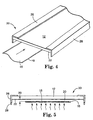
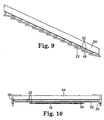
- Figures 1, 2, 4, 5, 8, 9, and 10 show examples of using capillary forces, along with other forces, to move the condensate on the condensing surface.
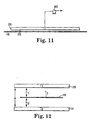
- FIG. 11 shows an example that use mechanical forces, along with capillary forces, to remove the condensate from the condensing surface.
- Figures 1 and 2 show an apparatus using two platens.
- Figures 4 and 5 show an apparatus using one platen.
- one platen has a condensing, liquid-transport surface located a short distance from the coated surface of the web. Distances of less than 15-20 cm are preferred. Distances less than 5 mm yield more advantages. Distances less than 0.5 mm and even distances as low as 0.1 mm and less are attainable.
- the apparatus 10 includes a condensing platen 12, which can be chilled, spaced from a heated platen 14.
- the condensing platen 12 is set to a temperature T 1 , which can be above or below ambient temperature
- the heated platen 14 is set to a temperature T 2 , which can be above or below ambient temperature.
- the coated web 16 temperature is T 3 .
- the web position is defined by h 1 , and h 2 , the distances between the respective facing surfaces of the web 16 and the condensing and heated platens.
- Figure 12 shows the relative locations of these variables.
- the total gap between the condensing platen and any heating platen, h is the total of h 1 , h 2 , and the coated web thickness.
- the web 16, having a coating 18, travels at any speed between the two platens.
- the web can be stationary and the entire apparatus 10 moves or both the web and apparatus move.
- the platens are stationary within the apparatus.
- the heated platen 14 is located on the non-coated side of the web 16, either in contact with the web or with a small gap h 2 between the web and the platen.
- the condensing platen 12 is located on the coated side of the web 16, with a small gap h 1 , between the web and the platen.
- the condensing platen 12 and the heated platen 14 eliminate the requirement for applied convection forces both above and below the web 16. Drying is controlled by adjusting the temperatures T 1 , T 2 , and distances h 1 , h 2 .
- the condensing platen 12 which can be stationary or mobile, is placed near the coated surface (such as cm away, 5 cm away, or closer).
- the arrangement of the platens creates a small gap adjacent the coated web.
- the gap is substantially constant, which permits small amounts of convergence or divergence. Also, the gap is substantially constant notwithstanding any grooves (discussed below) on the condensing surface.
- the orientation of the platens is not critical.
- the condensing platen 12 can be above the web (as shown in Figures 1, 2, 4-8, and 11-12), below the web (with the coating on the bottom surface of the web), and the system can operate with the web vertical or at any other angle, including being tilted around the axis of the direction of web travel.
- the heated platen 14 supplies energy without requiring applied convection through the web 16 to the coating 18 to evaporate liquid from the coating 18 to dry the coating. Energy is transferred by a combination of conduction, radiation, and convection achieving high heat transfer rates. This evaporates the liquid in the coating 18 on the web 16. The evaporated liquid from the coating 18 then is transported (using diffusion and convection) across the gap h 1 , between the web 16 and the condensing platen 12 and condenses on the bottom surface of the condensing platen 12.
- the bottom surface of the condensing platen 12 is the condensing surface 22 and has transverse open channels or grooves 24 which use capillary forces to prevent the condensed liquid from returning to the coating by gravity and to move the condensed liquid laterally to edge plates 26.
- the grooves can be triangular, rectangular, circular, or other more complex shapes or combinations of shapes.
- the groove material, geometry, and dimensions are designed to accommodate the required mass flow and the physical properties of the condensate, such as surface tension, viscosity, and density.
- a specific type of condensing surface is one, which has open channels or grooves with corners.
- This type of capillary condensing surface shown for example in Figure 3, is a geometrically specific surface, which can be designed with the aid of the Concus-Finn Inequality (Concus P. and Finn R. "On the Behavior of a Capillary Surface in a Wedge,” Proceeding of the National Academy of Science, vol. 63, 292-299 (1969) which is: ⁇ + ⁇ s ⁇ 90°, where ⁇ is half the included angle of any corner and ⁇ s is the gas/liquid/solid static contact angle.
- the static contact angle is governed by the surface tension of the liquid for a given surface material in gas.
- the interface is bounded; if the inequality is satisfied, the interface does not have a finite equilibrium position and the meniscus is unbounded. In this latter case, the liquid will advance by capillarity indefinitely or to the end of the channel or groove. Cornered grooved surfaces are helpful when the coating liquid has a high surface tension, such as water. Capillary surfaces with corners are discussed in great detail in Lopez de Ramos, A. L., "Capillary Enhanced Diffusion Of CO 2 in Porous Media,” Ph.D. Dissertation, University of Tulsa (1993).
- the grooves 24 also can be longitudinal or in any other direction. If the grooves are in the longitudinal direction, a suitable collection system can be placed at the ends of the grooves to prevent the condensed liquid from falling back to the coated surface 18. This embodiment limits the length of a condensing plate 12 and also limits the minimum gap h 1 .
- the edge plates 26 can be used with any condensing surface, not just one having grooves.
- the droplets 28 fall from each edge plate 26 and can be collected in a collecting device (not shown). For example, a slotted pipe can be placed around the bottom edge of each edge plate 26 to collect the liquid and direct it to a container.
- edge plates 26 are shown throughout the application as contacting the ends of the condensing surface of the condensing platens. However, the edge plates can be adjacent the condensing platens without contacting them as long as they are functionally close enough to receive the condensed liquid.
- the condensed liquid need not be removed from the platen at all, as long as it is removed from the condensing surface 22, or at least prevented from returning to the web 16.
- the edge plates 26 are shown as perpendicular to the condensing surface 14, although they can be at other angles with it, and the edge plates 26 can be smooth, grooved, porous, or other materials.
- the heated platen 14 and the condensing platen 12 can include internal passageways, such as channels.
- a heat transfer fluid can be heated by an external heating system and circulated through the passageways to set the temperature T 2 of the heated platen 14.
- the same or a different heat transfer fluid can be cooled by an external chiller and circulated through the passageways to set the temperature T 1 of the condensing platen 12.
- Other mechanisms for heating the platen 14 and cooling the platen 12 can be used.
- the apparatus 30 of Figures 4 and 5 is similar to that of Figures 1-3 except there is no heating platen.
- the web 16 is heated to evaporate the liquid from the coating by any heating method or combination of heating methods, whether conduction, radiation, microwave, convection, or ambient energy, using any type of heater.
- This can include but is not limited to a heated drum, radiant heating devices, or forced gas flows.
- This system can even operate without any applied energy, even outside the dryer, using only ambient energy to evaporate the liquid.
- the apparatus otherwise operates the same as that of Figures 1-3, without requiring applied convection for transport of the evaporated liquid from the web 16 to the condensing surface 22 on the condensing platen 12.
- the gap h, between the coated web 16 and the condensing surface 22 is isolated from the heating devices by any combination of the web 16 and web supports or other barriers. This can isolate the area from any applied convection.
- Capillarity can be combined with gravity.
- Figures 6 and 7 show embodiments of the apparatus where gravity is used in conjunction with capillarity to move the liquid solvent on the condensing surface.
- the condensing surface 22 is on a plate 42 which is tilted to one transverse side of the web 16 in Figure 6 and the condensing surface 22 is on one or two plates 44 which are tilted from the center to both transverse sides of the web 16 in Figure 7.
- capillarity and gravity are used to move the liquid away from the condensing surface.
- the angle could be centered on the longitudinal centerline of the web or it can be off-center.
- FIG 8 is another embodiment where capillary forces move the liquid on the condensing surface.
- the condensing plate 46 is a porous or wicking material, such as sintered metal or sponge, which uses capillary forces to transport the liquid solvent.
- the solvent condenses on the condensing surface 22 and is distributed throughout the condensing plate 46 due to capillary forces.
- the edge plates 26 adjacent the condensing plate 46 form a capillary surface.
- a liquid meniscus forms and creates a low pressure region which draws the condensate from the condensing surface to at least one edge plate. Gravity overcomes the capillary force and the liquid flows as a film or droplets down the surface of the edge plate 26.
- FIG 9 shows another embodiment where capillary and gravity forces are used to transport the condensed liquid on the condensing surfaces 22.
- condensing surfaces 22 are formed on many surfaces.
- a condensing platen 50 is tilted to one side or from the center to both sides above the web 16.
- Thin sheets 48 of material are suspended below the condensing platen 50 and located such that they are slanted away from the horizontal with their lower edge facing the lower edge of the condensing platen 50.
- the sheets 48 of material overlap by at least 0.05 cm and are spaced apart in the overlap region by a 0.01-0.25 cm slot. Vapor that condenses on the condensing surfaces 22 will be retained on the surfaces by surface tension.
- Figure 10 is another embodiment which can combine gravity and capillary forces to transport the liquid on the condensing surface.
- a porous, slotted, sponge, honeycomb, screened, or otherwise foraminous material 52 is attached to and located below a condensing platen 54.
- the spacing between the condensing platen 54 and the foraminous material 52, the dimensions of the foramina in the material 52, and the ratio of open area to solid area on the foraminous material 52 are all designed to cause the surface tension forces to retain the liquid on the three condensing surfaces 22.
- the apparatus is located adjacent to the web 16. Vapor condensing on the condensing surfaces 22 will be retained as liquid in the voids of the foraminous material and in the plate spacing region 56.
- liquid on the side of the foraminous material 52 facing the web 16 will be transported by capillary forces to fill the void in the plate spacing region 56.
- Liquid can be removed from the plate spacing region 56 either by gravity, capillary, or mechanical forces. By sloping the condensing platen 54 away from the horizontal in any direction, gravitational forces will remove liquid from the plate spacing region 56 to a point beyond the edge of the web 16.
- the liquid can be removed from the plate spacing region 56 by positioning at least one edge plate 26 at the edge of the condensing platen 54.
- the edge plate 26 contacts the condensing platen 54 to form a capillary surface.
- the edge plates can, in some uses, contact the foraminous material 22.
- a liquid meniscus forms and creates a low pressure region which draws the condensate toward at least one edge plate. Gravity overcomes the capillary force and the liquid flows as a film or droplets down the surface of the edge plate 26. Also, the condensate can be mechanically pumped out of the plate spacing region 56.
- FIG 11 schematically shows an embodiment, which uses a pump 80 to remove the condensed liquid from the condensing surface.
- the pump can be any type of pump, and any other device for creating negative pressure can be used.
- the condensed liquid can be driven toward the transverse center of the condensing surface before removal, such as by capillarity and gravity.
- the system can first remove fluid from a coated substrate. Then, the system, at a downweb location from the drying location, can be used "in reverse" to add some small portion of moisture or additional reactant to the substrate to modify the coating.
- the apparatus can operate outside of a dryer configuration without any applied energy, and with only ambient heat to evaporate the liquid.
- the temperature of the condensing surface 22 By controlling the temperature of the condensing surface 22 to be at or near the ambient temperature, the liquid evaporation will only occur until the vapor concentration in the gap h, between the condensing surface and the web 16 is at the saturated concentration as defined by the condensing surface 22 and web 16 temperatures.
- the liquid that has evaporated will be contained and carried by the viscous drag of the web through the gap h, to the exit of the system. Undesirable drying can be reduced and vapor emissions can be isolated from ambient conditions.
- the drying system of the invention can be used to reduce or virtually stop the drying of the coating.
- the rate of drying is a function of the gap height and vapor concentration gradient between the coated surface 18 of the web 16 and the condensing surface 22.
- the temperature differential between the web 16 and the condensing surface 22 defines the vapor concentration gradient.
- the vapor concentration gradient cannot be controlled without using an expensive inert gas drying system.
- Some liquid coatings have multiple solvents where one or more of the solvents function to slow down the rate of drying for optimum product properties.
- the rate of drying is controlled by the height of the gap h 1 , and the temperature differential between the coated surface 18 and the condensing surface 22. Therefore for a given temperature differential, the rate of drying can be controlled by the position of the condensing plate which defines the gap h 1 .
- the rate of drying can be controlled by the position of the condensing plate which defines the gap h 1 .
- Conventional dryers do not have this capability.
- Mottle patterns are defects in film coatings that are formed by vapor concentration or gas velocity gradients above the coating, which cause non-uniform drying at the liquid surface. Normal room air currents are often sufficient to create these defects.
- the invention can be used to reduce and control natural convection induced defects, such as mottle, at locations outside the desired drying position. In locations where the coated surface is not in the drying region and would otherwise be exposed to convection from either ambient air currents or from a turbulent boundary layer air due to web movement, the apparatus, with grooves or other liquid transport and removal features, devices, structures or without, can be located adjacent to the coated web 16 separated by a gap hl.
- the location of the condensing plate 12 adjacent the coated web 16 can isolate the ambient air currents from the coating surface. It can also prevent the boundary layer air above the coated surface from becoming turbulent. Accordingly, defects due to convection outside the drying position, such as mottle, can be reduced or eliminated.
- the apparatus can be operated with condensation and solvent removal similar to Figures 4-12, or it can even operate without condensation and solvent removal by raising the condensing surface 22 temperature above the dew point of the vapors in the gap h 1 .
- each pair of heating and condensing components can be controlled independently of the other pairs.
- the zones can be spaced from each other or not.
- the systems of all of the embodiments use condensation close to the coated web 16 with a small gap between the coating on the web 16 and the condensing surface 22. There is no requirement for applied convection and there is very little vapor volume.
- the vapor concentration and convection forces can be controlled by adjusting the web temperature, the gap, and the condensing surface temperature. This provides improved control of the conditions near the gas/liquid interface. Because the plate temperatures and gap can be continuous and constant throughout the drying system, heat and mass transfer rates are more uniformly controlled than with conventional drying systems. All of these factors contribute to improved drying performance. It also improves the efficiency of the condensation vapor recovery systems, providing for liquid recovery at high efficiencies at no additional cost compared to known expensive methods of burning, adsorption, or condensation in a secondary gas stream.
- a mottle-prone polymer/MEK solution at 11.5% solids, 2 centipoise, 7.6 micron wet thickness, and 20.3 cm wide was coated.
- the web was 21.6 cm wide and traveled at a speed of 0.635 m/s.
- the temperature of the heated platen used to heat the web was controlled at 82°C.
- the condensing platen temperature was controlled at 27°C.
- the overall length of the platens was 1.68 m and they were mounted at a 3.4° angle from horizontal with the inlet side at a lower elevation.
- the inlet to the platens was located 76 cm from the coating application point.
- the heated platen was separated from the web by a gap of approximately 0.076 cm.
- the gap h 1 was set at 0.32 cm.
- the capillary grooves were 0.0381 cm deep with a .076 cm peak-to-peak distance, an angle ⁇ of 30°, and 0.013 cm land at the top of the grooves.
- the web was dried mottle-free in the 1.68 m length of the platens although there was some residual solvent in the coating when it left the platens.
- a conventional dryer would require approximately 9 m to reach the same drying point, requiring the dryer to be more than five times larger.
- Blister defects may be caused by the coating surface forming a dried skin before the rest of the coating has dried, trapping solvent below this skin.
- the solvent vapor concentration in the bulk gas is very low because of flammability limits. If too much heat is applied to the coating, the solvent at the surface will flash very quickly into the low vapor concentration gas stream and will form the skin on the surface.
- the system of this invention creates a controlled vapor concentration in the space above the web, which can reduce the tendency to form a skin on the surface.
- Other applications are in areas where dryers are run at high solvent concentrations to obtain specific product performance.
- the system provides advantages beyond solvent recovery and drying performance.
- Another advantage involves a simplified process for subjecting the coating fluid to a magnetic field.
- the magnetic field generator can be positioned outside of the dryer (i.e., outside of apparatus 10, 30). This is enabled by the compact nature of the apparatus. This is especially suitable when coating a metal particulate- loaded fluid onto a substrate to make such products as video and audio recording tape, computer and data storage tape, computer diskettes, and the like. Being outside of the apparatus, the magnetic field generators are easily adjustable and maintained.
- This setup also improves particle orientation. Magnetic output is improved if the particles are physically oriented in the direction of recording. Conventionally the orienting device is contained within the dryer and the particles are oriented at a single point or multiple points as the solvent is removed.
- One advantage here is that because the magnetic orienting device is outside of the dryer and is non-intrusive (conventional orienting devices inside the dryer disrupt the convection heat and mass transfer), it will not affect the solvent removal rates in any way. This allows uniform solvent removal. The magnetic particles are easily oriented when the fluid is less viscous at the early stages of drying with this invention.
- any components of the magnetic field which are not in the plane of the coating will reorient the particles in a non-preferred direction, such as tipping them vertically.
- the viscosity increases, making it difficult for the orienting device to rotate the particles. The particles will not be reoriented when leaving the field or by interparticle forces.
- the invention allows orienting particles at the beginning of the dryer and orienting device.
- the uniform field holds the particles in the preferred direction as the solvent is removed in a uniform drying environment to such a level that the viscosity is increased to the point that the viscous forces dominate. This prevents undesirable particle disorientation as it leaves the orienting device or from interparticle forces. Drying in conventional dryers causes the surface of the product to roughen. Removing the solvent in the controlled environment of the dryer of this invention appears to create smoother surfaces at elevated solvent removal rates. This also improves magnetic output as, for example, the resulting tape will ride closer to the recording head.
Landscapes
- Engineering & Computer Science (AREA)
- Mechanical Engineering (AREA)
- General Engineering & Computer Science (AREA)
- Textile Engineering (AREA)
- Life Sciences & Earth Sciences (AREA)
- Dispersion Chemistry (AREA)
- Chemical & Material Sciences (AREA)
- Microbiology (AREA)
- Drying Of Solid Materials (AREA)
- Application Of Or Painting With Fluid Materials (AREA)
- Coating Apparatus (AREA)
- Cleaning Or Drying Semiconductors (AREA)
- Manufacturing Of Magnetic Record Carriers (AREA)
- Exposure And Positioning Against Photoresist Photosensitive Materials (AREA)
- Exposure Of Semiconductors, Excluding Electron Or Ion Beam Exposure (AREA)
Description
Claims (22)
- A method of drying a substrate comprising:(a) locating a condensing surface spaced a short distance from a surface of said substrate to define a gap between said substrate and said condensing surface;(b) evaporating a liquid from said substrate to create a vapor;(c) condensing the vapor on the condensing surface to create a condensate; and(d) moving the condensate on the condensing surface using at least capillary forces, so as to allow subsequent removal of condensate from the condensing surface.
- The method according to claim 1, further comprising removing the condensate from the condensing surface.
- The method according to claim 1, wherein the capillary forces are provided by channels or grooves on a condensing platen or foraminous material in contact with or spaced apart from the condensing platen.
- The method according to claim 1, wherein said condensate is transported to at least one edge of said condensing surface.
- The method according to claim 4, wherein said condensing surface includes at least one edge plate for removal of said condensate.
- The method according to claim 1, wherein the condensing surface is located at least one of: above the substrate, and less than 5 mm from the substrate.
- The method according to claim 2, wherein removing of said condensate includes the use of gravity, mechanical forces, capillary forces or combinations thereof.
- The method according to claim 1, further comprising creating relative motion between the substrate and the condensing surface by moving the substrate while maintaining the condensing surface stationary.
- The method according to claim 8, wherein removal of said condensate is transverse to the substrate motion.
- The method according to claims 1-9, wherein said substrate is a web or coated web.
- The method according to claim 1, wherein said condensing surface includes a plurality of condensing plates.
- The method according to claim 1, further comprising a heated platen in contact with said substrate or in close proximity to a surface of said substrate to define a gap between the heated platen or the surface of said substrate.
- The method according to claims 1-12, wherein energy transfer and mass transfer between said substrate and said heated platen or said substrate and said condensing surface are controlled by adjusting at least one of the gap between the substrate and the condensing surface, the gap between the substrate and the heated platen, the temperature of the heated platen or the temperature of the condensing surface.
- An apparatus for drying a substrate comprising:a condensing surface spaced a short distance from a substrate to define a gap between said substrate and said condensing surface;means for evaporating a liquid from said substrate to create a vapor, at least a portion of said vapor contacting said condensing surface and forming condensate; andmeans for moving said condensate on said condensing surface using at least capillary forces, so as to allow subsequent removal of condensate from the condensing surface.
- The apparatus of claim 14, further comprising means for removing the condensate from the condensing surface.
- The apparatus of claim 14 or 15, further comprising a means for moving the substrate relative to the condensing surface, and wherein the condensing surface is stationary.
- The apparatus of claim 15, wherein the means for removing the condensate comprises at least one edge plate in communication with the condensing surface.
- The apparatus of claim 14, wherein the capillary forces are provided by channels or grooves on said condensing surface or by foraminous material in contact with, or spaced apart from said condensing surface.
- The apparatus of claim 15, wherein removing of said condensate includes use of gravity, mechanical forces, capillary forces or combinations thereof.
- The apparatus of claim 14, wherein the substrate is a web or coated web.
- The apparatus of claim 14, wherein the means for evaporating the liquid includes a heated platen in contact with said substrate or in close proximity to a surface of said substrate to define a gap between the heated platen or the surface of said substrate.
- The apparatus of claims 14-21, wherein energy and mass transfer between said substrate and said heated platen or said substrate and said condensing surface are controlled by adjusting at least one of the gap between the substrate and the condensing surface, the gap between the substrate and the heated platen, the temperature of the heated platen or the temperature of the condensing surface.
Priority Applications (4)
| Application Number | Priority Date | Filing Date | Title |
|---|---|---|---|
| EP01129624A EP1191295B1 (en) | 1995-09-18 | 1996-09-09 | Method for drying a substrate |
| EP01129625A EP1195564B1 (en) | 1995-09-18 | 1996-09-09 | Coated substrate drying system |
| EP05020576A EP1632741A3 (en) | 1995-09-18 | 1996-09-09 | Method for applying a component to a substrate |
| EP05020575A EP1632740A3 (en) | 1995-09-18 | 1996-09-09 | Method for controlling a processing environment |
Applications Claiming Priority (5)
| Application Number | Priority Date | Filing Date | Title |
|---|---|---|---|
| US08/536,593 US5581905A (en) | 1995-09-18 | 1995-09-18 | Coated substrate drying system |
| US536593 | 1995-09-18 | ||
| US699522 | 1996-09-04 | ||
| US08/699,522 US5694701A (en) | 1996-09-04 | 1996-09-04 | Coated substrate drying system |
| PCT/US1996/014435 WO1997011328A1 (en) | 1995-09-18 | 1996-09-09 | Coated substrate drying system |
Related Child Applications (2)
| Application Number | Title | Priority Date | Filing Date |
|---|---|---|---|
| EP01129624A Division EP1191295B1 (en) | 1995-09-18 | 1996-09-09 | Method for drying a substrate |
| EP01129625A Division EP1195564B1 (en) | 1995-09-18 | 1996-09-09 | Coated substrate drying system |
Publications (2)
| Publication Number | Publication Date |
|---|---|
| EP0851997A1 EP0851997A1 (en) | 1998-07-08 |
| EP0851997B1 true EP0851997B1 (en) | 2003-04-09 |
Family
ID=27065191
Family Applications (5)
| Application Number | Title | Priority Date | Filing Date |
|---|---|---|---|
| EP01129624A Expired - Lifetime EP1191295B1 (en) | 1995-09-18 | 1996-09-09 | Method for drying a substrate |
| EP01129625A Expired - Lifetime EP1195564B1 (en) | 1995-09-18 | 1996-09-09 | Coated substrate drying system |
| EP96930780A Expired - Lifetime EP0851997B1 (en) | 1995-09-18 | 1996-09-09 | Procedure and device for drying a coated substrate |
| EP05020575A Withdrawn EP1632740A3 (en) | 1995-09-18 | 1996-09-09 | Method for controlling a processing environment |
| EP05020576A Withdrawn EP1632741A3 (en) | 1995-09-18 | 1996-09-09 | Method for applying a component to a substrate |
Family Applications Before (2)
| Application Number | Title | Priority Date | Filing Date |
|---|---|---|---|
| EP01129624A Expired - Lifetime EP1191295B1 (en) | 1995-09-18 | 1996-09-09 | Method for drying a substrate |
| EP01129625A Expired - Lifetime EP1195564B1 (en) | 1995-09-18 | 1996-09-09 | Coated substrate drying system |
Family Applications After (2)
| Application Number | Title | Priority Date | Filing Date |
|---|---|---|---|
| EP05020575A Withdrawn EP1632740A3 (en) | 1995-09-18 | 1996-09-09 | Method for controlling a processing environment |
| EP05020576A Withdrawn EP1632741A3 (en) | 1995-09-18 | 1996-09-09 | Method for applying a component to a substrate |
Country Status (11)
| Country | Link |
|---|---|
| EP (5) | EP1191295B1 (en) |
| JP (2) | JP3874799B2 (en) |
| KR (3) | KR100449961B1 (en) |
| CN (2) | CN1269546C (en) |
| AU (1) | AU696910B2 (en) |
| BR (1) | BR9610658A (en) |
| CA (1) | CA2229870A1 (en) |
| DE (3) | DE69635682T2 (en) |
| ES (3) | ES2191107T3 (en) |
| PT (2) | PT851997E (en) |
| WO (1) | WO1997011328A1 (en) |
Families Citing this family (31)
| Publication number | Priority date | Publication date | Assignee | Title |
|---|---|---|---|---|
| USRE38412E1 (en) | 1996-09-04 | 2004-02-03 | Imation Corp. | Coated substrate drying system with magnetic particle orientation |
| US5813133A (en) * | 1996-09-04 | 1998-09-29 | Minnesota Mining And Manufacturing Company | Coated substrate drying system with magnetic particle orientation |
| EP0897092A1 (en) * | 1997-08-08 | 1999-02-17 | Voith Sulzer Papiertechnik Patent GmbH | Condensation drying |
| US6134808A (en) * | 1998-05-18 | 2000-10-24 | Minnesota Mining And Manufacturing Company | Gap drying with insulation layer between substrate and heated platen |
| US6808739B2 (en) * | 2000-09-24 | 2004-10-26 | 3M Innovative Properties Company | Drying method for selectively removing volatile components from wet coatings |
| EP1320452B1 (en) * | 2000-09-24 | 2007-12-05 | 3M Innovative Properties Company | Extrusion method and apparatus for manufacturing microporous film |
| JP4631242B2 (en) * | 2001-09-27 | 2011-02-16 | 富士フイルム株式会社 | Coating film drying method and apparatus |
| JP4763184B2 (en) * | 2001-09-27 | 2011-08-31 | 富士フイルム株式会社 | Solution casting method and apparatus |
| JP5358908B2 (en) * | 2007-08-02 | 2013-12-04 | 大日本印刷株式会社 | Color filter manufacturing apparatus, color filter manufacturing method, drying apparatus, drying method, display apparatus manufacturing apparatus, display apparatus manufacturing method |
| TW201005813A (en) | 2008-05-15 | 2010-02-01 | Du Pont | Process for forming an electroactive layer |
| KR101007896B1 (en) * | 2009-02-12 | 2011-01-14 | 주식회사 희람테크 | Communication cable terminal box structure |
| KR20110134452A (en) | 2009-03-06 | 2011-12-14 | 이 아이 듀폰 디 네모아 앤드 캄파니 | Method for Forming Electroactive Layer |
| EP2406814A4 (en) | 2009-03-09 | 2012-07-25 | Du Pont | METHOD FOR FORMING AN ELECTROACTIVE LAYER |
| US9209398B2 (en) | 2009-03-09 | 2015-12-08 | E I Du Pont De Nemours And Company Dupont Displays Inc | Process for forming an electroactive layer |
| JP5503937B2 (en) * | 2009-10-08 | 2014-05-28 | 日産自動車株式会社 | Electrode drying apparatus and electrode drying method |
| JP5222333B2 (en) * | 2010-09-09 | 2013-06-26 | 富士フイルム株式会社 | Coating film drying method and apparatus |
| WO2014012223A1 (en) * | 2012-07-18 | 2014-01-23 | Lee Shangyo | Normal temperature drying system |
| JP6149547B2 (en) * | 2013-07-01 | 2017-06-21 | コニカミノルタ株式会社 | Wet image forming device |
| JP6909617B2 (en) * | 2016-09-30 | 2021-07-28 | 東京エレクトロン株式会社 | Decompression drying device |
| CN109200736B (en) * | 2017-06-30 | 2021-01-08 | 京东方科技集团股份有限公司 | Condensing plate, vacuum drying equipment and vacuum drying method |
| CN109216573A (en) * | 2017-06-30 | 2019-01-15 | 京东方科技集团股份有限公司 | The preparation method of cold plate and preparation method thereof, drying equipment, oled panel |
| DE102017128397A1 (en) * | 2017-11-30 | 2019-06-06 | Mitsubishi Hitec Paper Europe Gmbh | Method and device for producing a coated substrate and coated substrate |
| CN108541143B (en) * | 2018-03-13 | 2021-07-13 | 广西师范大学 | A kind of preparation device and preparation method of polyimide copper clad laminate |
| CN108527745B (en) * | 2018-03-13 | 2021-03-02 | 广西师范大学 | A preparation device and preparation method of polyimide thick film or polyimide ultra-thick film |
| CN109406247A (en) * | 2018-10-26 | 2019-03-01 | 杭州依美洛克医学科技有限公司 | Discharger for micro slide experiment liquid |
| US12343953B2 (en) | 2018-11-09 | 2025-07-01 | 3M Innovative Properties Company | Nanostructured optical films and intermediates |
| CN110128033A (en) * | 2019-05-23 | 2019-08-16 | 深圳市华星光电技术有限公司 | A kind of roasting plant |
| KR102794049B1 (en) * | 2019-07-12 | 2025-04-11 | 주식회사 엘지화학 | Apparatus for drying film |
| JP6907280B2 (en) * | 2019-09-12 | 2021-07-21 | 中外炉工業株式会社 | Decompression drying device |
| CN111589628B (en) * | 2020-04-28 | 2021-04-09 | 台州伟志机床股份有限公司 | Low-loss-rate quick-drying type spraying equipment for anti-rust oil for plates |
| CN112122081B (en) * | 2020-09-23 | 2024-09-10 | 深圳市善营自动化科技有限公司 | Drying method and device for coating substrate |
Family Cites Families (17)
| Publication number | Priority date | Publication date | Assignee | Title |
|---|---|---|---|---|
| BE464050A (en) * | ||||
| DE421890C (en) * | ||||
| GB1253124A (en) * | 1969-02-28 | 1971-11-10 | ||
| AT321257B (en) * | 1971-05-26 | 1975-03-25 | Koreska Gmbh W | Plant for the recovery of volatile solvents |
| GB1502040A (en) * | 1975-12-30 | 1978-02-22 | Tampella Oy Ab | Method of drying a cardboard or a paper web and drying device for applying this method |
| FI59636C (en) * | 1976-08-25 | 1981-09-10 | Tampella Oy Ab | TORKANLAEGGNING FOER TORKNING AV EN PAPPERS- KARTONG-ELLER TEXTILBANA ELLER ANNAN FIBRIG ELLER POROES BANA |
| FI59439C (en) * | 1980-04-25 | 1981-08-10 | Tampella Oy Ab | FOERFARANDE FOER ATT UTNYTTJANDE AV ENTALPIINNEHAOLLET I KYLVATTNET VID EN SUGTORKNINGSPROCESS FOER PAPPER CARTON ELLER EN ANNAN POROES MATTA ELLER BANA |
| JPS57134558A (en) * | 1981-02-16 | 1982-08-19 | Fuji Photo Film Co Ltd | Production of organic vapor deposited thin film |
| FI61537C (en) * | 1981-02-19 | 1982-08-10 | Tampella Oy Ab | REFERENCE TO A CONTAINER WITHOUT CONTAINER TORKNING AV EN PAPPERS- ELLER LIKNANDE POROES BANA |
| US4365423A (en) | 1981-03-27 | 1982-12-28 | Eastman Kodak Company | Method and apparatus for drying coated sheet material |
| JPS57198544A (en) * | 1981-05-28 | 1982-12-06 | Sony Corp | Manufacture of magnetic recording medium |
| JPS5880136A (en) * | 1981-11-02 | 1983-05-14 | Fuji Photo Film Co Ltd | Manufacture of magnetic recording material |
| DE3240063A1 (en) * | 1981-11-02 | 1983-05-26 | Basf Ag, 6700 Ludwigshafen | Apparatus for producing a magnetogram carrier |
| JPH0656656B2 (en) * | 1983-10-03 | 1994-07-27 | 富士写真フイルム株式会社 | Method of manufacturing magnetic recording medium |
| JPS6292132A (en) * | 1985-10-18 | 1987-04-27 | Fuji Photo Film Co Ltd | Manufacture of magnetic recording medium |
| US4923766A (en) * | 1988-03-29 | 1990-05-08 | Canon Kabushiki Kaisha | Process for preparing magnetic recording |
| DE4009797A1 (en) * | 1990-03-27 | 1991-10-02 | Pagendarm Gmbh | METHOD AND ARRANGEMENT FOR CONDENSING VAPOROUS SUBSTANCES |
-
1996
- 1996-09-09 EP EP01129624A patent/EP1191295B1/en not_active Expired - Lifetime
- 1996-09-09 WO PCT/US1996/014435 patent/WO1997011328A1/en not_active Ceased
- 1996-09-09 PT PT96930780T patent/PT851997E/en unknown
- 1996-09-09 KR KR10-2004-7004557A patent/KR100449961B1/en not_active Expired - Fee Related
- 1996-09-09 CN CNB031041523A patent/CN1269546C/en not_active Expired - Fee Related
- 1996-09-09 DE DE69635682T patent/DE69635682T2/en not_active Expired - Lifetime
- 1996-09-09 ES ES96930780T patent/ES2191107T3/en not_active Expired - Lifetime
- 1996-09-09 DE DE69627357T patent/DE69627357T2/en not_active Expired - Lifetime
- 1996-09-09 PT PT01129625T patent/PT1195564E/en unknown
- 1996-09-09 ES ES01129625T patent/ES2256146T3/en not_active Expired - Lifetime
- 1996-09-09 EP EP01129625A patent/EP1195564B1/en not_active Expired - Lifetime
- 1996-09-09 DE DE69635530T patent/DE69635530T2/en not_active Expired - Lifetime
- 1996-09-09 EP EP96930780A patent/EP0851997B1/en not_active Expired - Lifetime
- 1996-09-09 EP EP05020575A patent/EP1632740A3/en not_active Withdrawn
- 1996-09-09 CN CNB961969962A patent/CN1145775C/en not_active Expired - Lifetime
- 1996-09-09 JP JP51275097A patent/JP3874799B2/en not_active Expired - Fee Related
- 1996-09-09 KR KR10-2004-7004554A patent/KR100485832B1/en not_active Expired - Lifetime
- 1996-09-09 EP EP05020576A patent/EP1632741A3/en not_active Withdrawn
- 1996-09-09 ES ES01129624T patent/ES2253321T3/en not_active Expired - Lifetime
- 1996-09-09 BR BR9610658A patent/BR9610658A/en not_active IP Right Cessation
- 1996-09-09 KR KR10-1998-0701975A patent/KR100449962B1/en not_active Expired - Fee Related
- 1996-09-09 AU AU69710/96A patent/AU696910B2/en not_active Ceased
- 1996-09-09 CA CA002229870A patent/CA2229870A1/en not_active Abandoned
-
2004
- 2004-11-04 JP JP2004320818A patent/JP4099474B2/en not_active Expired - Fee Related
Also Published As
Similar Documents
| Publication | Publication Date | Title |
|---|---|---|
| EP1191295B1 (en) | Method for drying a substrate | |
| US5694701A (en) | Coated substrate drying system | |
| US5813133A (en) | Coated substrate drying system with magnetic particle orientation | |
| US5581905A (en) | Coated substrate drying system | |
| JP3993636B2 (en) | Component separation system including condensation mechanism | |
| JP4302889B2 (en) | Gap drying using an insulating layer between the substrate and the heated platen | |
| EP1462746A2 (en) | Drying method and drying apparatus for coating layer | |
| USRE38412E1 (en) | Coated substrate drying system with magnetic particle orientation | |
| HK1015025B (en) | Procedure and device for drying a coated substrate | |
| MXPA98001965A (en) | Substrate drying system recubie |
Legal Events
| Date | Code | Title | Description |
|---|---|---|---|
| PUAI | Public reference made under article 153(3) epc to a published international application that has entered the european phase |
Free format text: ORIGINAL CODE: 0009012 |
|
| 17P | Request for examination filed |
Effective date: 19980401 |
|
| AK | Designated contracting states |
Kind code of ref document: A1 Designated state(s): BE DE ES FR GB IE IT NL PT |
|
| 17Q | First examination report despatched |
Effective date: 19980724 |
|
| RTI1 | Title (correction) |
Free format text: PROCEDURE AND DEVICE FOR DRYING A COATED SUBSTRATE |
|
| GRAH | Despatch of communication of intention to grant a patent |
Free format text: ORIGINAL CODE: EPIDOS IGRA |
|
| GRAH | Despatch of communication of intention to grant a patent |
Free format text: ORIGINAL CODE: EPIDOS IGRA |
|
| GRAA | (expected) grant |
Free format text: ORIGINAL CODE: 0009210 |
|
| AK | Designated contracting states |
Designated state(s): BE DE ES FR GB IE IT NL PT |
|
| REG | Reference to a national code |
Ref country code: GB Ref legal event code: FG4D |
|
| REG | Reference to a national code |
Ref country code: IE Ref legal event code: FG4D |
|
| REG | Reference to a national code |
Ref country code: ES Ref legal event code: FG2A Ref document number: 2191107 Country of ref document: ES Kind code of ref document: T3 |
|
| ET | Fr: translation filed | ||
| PLBE | No opposition filed within time limit |
Free format text: ORIGINAL CODE: 0009261 |
|
| STAA | Information on the status of an ep patent application or granted ep patent |
Free format text: STATUS: NO OPPOSITION FILED WITHIN TIME LIMIT |
|
| 26N | No opposition filed |
Effective date: 20040112 |
|
| PGFP | Annual fee paid to national office [announced via postgrant information from national office to epo] |
Ref country code: IE Payment date: 20070924 Year of fee payment: 12 |
|
| PGFP | Annual fee paid to national office [announced via postgrant information from national office to epo] |
Ref country code: ES Payment date: 20070926 Year of fee payment: 12 |
|
| PGFP | Annual fee paid to national office [announced via postgrant information from national office to epo] |
Ref country code: GB Payment date: 20070926 Year of fee payment: 12 |
|
| PGFP | Annual fee paid to national office [announced via postgrant information from national office to epo] |
Ref country code: BE Payment date: 20071025 Year of fee payment: 12 |
|
| PGFP | Annual fee paid to national office [announced via postgrant information from national office to epo] |
Ref country code: NL Payment date: 20080924 Year of fee payment: 13 Ref country code: IT Payment date: 20080926 Year of fee payment: 13 Ref country code: FR Payment date: 20080917 Year of fee payment: 13 |
|
| REG | Reference to a national code |
Ref country code: PT Ref legal event code: MM4A Free format text: LAPSE DUE TO NON-PAYMENT OF FEES Effective date: 20090309 |
|
| BERE | Be: lapsed |
Owner name: *MINNESOTA MINING AND MFG CY Effective date: 20080930 |
|
| GBPC | Gb: european patent ceased through non-payment of renewal fee |
Effective date: 20080909 |
|
| PG25 | Lapsed in a contracting state [announced via postgrant information from national office to epo] |
Ref country code: PT Free format text: LAPSE BECAUSE OF NON-PAYMENT OF DUE FEES Effective date: 20090309 |
|
| REG | Reference to a national code |
Ref country code: IE Ref legal event code: MM4A |
|
| PG25 | Lapsed in a contracting state [announced via postgrant information from national office to epo] |
Ref country code: IE Free format text: LAPSE BECAUSE OF NON-PAYMENT OF DUE FEES Effective date: 20080909 Ref country code: BE Free format text: LAPSE BECAUSE OF NON-PAYMENT OF DUE FEES Effective date: 20080930 |
|
| REG | Reference to a national code |
Ref country code: ES Ref legal event code: FD2A Effective date: 20080910 |
|
| PG25 | Lapsed in a contracting state [announced via postgrant information from national office to epo] |
Ref country code: GB Free format text: LAPSE BECAUSE OF NON-PAYMENT OF DUE FEES Effective date: 20080909 |
|
| PGFP | Annual fee paid to national office [announced via postgrant information from national office to epo] |
Ref country code: PT Payment date: 20070822 Year of fee payment: 12 |
|
| PG25 | Lapsed in a contracting state [announced via postgrant information from national office to epo] |
Ref country code: ES Free format text: LAPSE BECAUSE OF NON-PAYMENT OF DUE FEES Effective date: 20080910 |
|
| REG | Reference to a national code |
Ref country code: NL Ref legal event code: V1 Effective date: 20100401 |
|
| REG | Reference to a national code |
Ref country code: FR Ref legal event code: ST Effective date: 20100531 |
|
| PG25 | Lapsed in a contracting state [announced via postgrant information from national office to epo] |
Ref country code: NL Free format text: LAPSE BECAUSE OF NON-PAYMENT OF DUE FEES Effective date: 20100401 Ref country code: FR Free format text: LAPSE BECAUSE OF NON-PAYMENT OF DUE FEES Effective date: 20090930 |
|
| PG25 | Lapsed in a contracting state [announced via postgrant information from national office to epo] |
Ref country code: IT Free format text: LAPSE BECAUSE OF NON-PAYMENT OF DUE FEES Effective date: 20090909 |
|
| PGFP | Annual fee paid to national office [announced via postgrant information from national office to epo] |
Ref country code: DE Payment date: 20150902 Year of fee payment: 20 |
|
| REG | Reference to a national code |
Ref country code: DE Ref legal event code: R071 Ref document number: 69627357 Country of ref document: DE |