EP0851989B1 - A light assembly - Google Patents
A light assembly Download PDFInfo
- Publication number
- EP0851989B1 EP0851989B1 EP96925627A EP96925627A EP0851989B1 EP 0851989 B1 EP0851989 B1 EP 0851989B1 EP 96925627 A EP96925627 A EP 96925627A EP 96925627 A EP96925627 A EP 96925627A EP 0851989 B1 EP0851989 B1 EP 0851989B1
- Authority
- EP
- European Patent Office
- Prior art keywords
- led
- light assembly
- light
- assembly
- circuitry
- Prior art date
- Legal status (The legal status is an assumption and is not a legal conclusion. Google has not performed a legal analysis and makes no representation as to the accuracy of the status listed.)
- Expired - Lifetime
Links
Images

Classifications
-
- F—MECHANICAL ENGINEERING; LIGHTING; HEATING; WEAPONS; BLASTING
- F21—LIGHTING
- F21S—NON-PORTABLE LIGHTING DEVICES; SYSTEMS THEREOF; VEHICLE LIGHTING DEVICES SPECIALLY ADAPTED FOR VEHICLE EXTERIORS
- F21S9/00—Lighting devices with a built-in power supply; Systems employing lighting devices with a built-in power supply
- F21S9/02—Lighting devices with a built-in power supply; Systems employing lighting devices with a built-in power supply the power supply being a battery or accumulator
- F21S9/03—Lighting devices with a built-in power supply; Systems employing lighting devices with a built-in power supply the power supply being a battery or accumulator rechargeable by exposure to light
- F21S9/037—Lighting devices with a built-in power supply; Systems employing lighting devices with a built-in power supply the power supply being a battery or accumulator rechargeable by exposure to light the solar unit and the lighting unit being located within or on the same housing
-
- E—FIXED CONSTRUCTIONS
- E01—CONSTRUCTION OF ROADS, RAILWAYS, OR BRIDGES
- E01F—ADDITIONAL WORK, SUCH AS EQUIPPING ROADS OR THE CONSTRUCTION OF PLATFORMS, HELICOPTER LANDING STAGES, SIGNS, SNOW FENCES, OR THE LIKE
- E01F9/00—Arrangement of road signs or traffic signals; Arrangements for enforcing caution
- E01F9/50—Road surface markings; Kerbs or road edgings, specially adapted for alerting road users
- E01F9/553—Low discrete bodies, e.g. marking blocks, studs or flexible vehicle-striking members
- E01F9/559—Low discrete bodies, e.g. marking blocks, studs or flexible vehicle-striking members illuminated
-
- F—MECHANICAL ENGINEERING; LIGHTING; HEATING; WEAPONS; BLASTING
- F21—LIGHTING
- F21V—FUNCTIONAL FEATURES OR DETAILS OF LIGHTING DEVICES OR SYSTEMS THEREOF; STRUCTURAL COMBINATIONS OF LIGHTING DEVICES WITH OTHER ARTICLES, NOT OTHERWISE PROVIDED FOR
- F21V23/00—Arrangement of electric circuit elements in or on lighting devices
- F21V23/04—Arrangement of electric circuit elements in or on lighting devices the elements being switches
- F21V23/0442—Arrangement of electric circuit elements in or on lighting devices the elements being switches activated by means of a sensor, e.g. motion or photodetectors
-
- F—MECHANICAL ENGINEERING; LIGHTING; HEATING; WEAPONS; BLASTING
- F21—LIGHTING
- F21V—FUNCTIONAL FEATURES OR DETAILS OF LIGHTING DEVICES OR SYSTEMS THEREOF; STRUCTURAL COMBINATIONS OF LIGHTING DEVICES WITH OTHER ARTICLES, NOT OTHERWISE PROVIDED FOR
- F21V31/00—Gas-tight or water-tight arrangements
- F21V31/04—Provision of filling media
-
- G—PHYSICS
- G08—SIGNALLING
- G08B—SIGNALLING SYSTEMS, e.g. PERSONAL CALLING SYSTEMS; ORDER TELEGRAPHS; ALARM SYSTEMS
- G08B5/00—Visible signalling systems, e.g. visible personal calling systems or remote indication of seats occupied
- G08B5/22—Visible signalling systems, e.g. visible personal calling systems or remote indication of seats occupied using electric transmission; using electromagnetic transmission
- G08B5/36—Visible signalling systems, e.g. visible personal calling systems or remote indication of seats occupied using electric transmission; using electromagnetic transmission using visible light sources
- G08B5/38—Visible signalling systems, e.g. visible personal calling systems or remote indication of seats occupied using electric transmission; using electromagnetic transmission using visible light sources using flashing light
-
- H—ELECTRICITY
- H05—ELECTRIC TECHNIQUES NOT OTHERWISE PROVIDED FOR
- H05B—ELECTRIC HEATING; ELECTRIC LIGHT SOURCES NOT OTHERWISE PROVIDED FOR; CIRCUIT ARRANGEMENTS FOR ELECTRIC LIGHT SOURCES, IN GENERAL
- H05B47/00—Circuit arrangements for operating light sources in general, i.e. where the type of light source is not relevant
- H05B47/10—Controlling the light source
- H05B47/105—Controlling the light source in response to determined parameters
- H05B47/11—Controlling the light source in response to determined parameters by determining the brightness or colour temperature of ambient light
-
- F—MECHANICAL ENGINEERING; LIGHTING; HEATING; WEAPONS; BLASTING
- F21—LIGHTING
- F21W—INDEXING SCHEME ASSOCIATED WITH SUBCLASSES F21K, F21L, F21S and F21V, RELATING TO USES OR APPLICATIONS OF LIGHTING DEVICES OR SYSTEMS
- F21W2111/00—Use or application of lighting devices or systems for signalling, marking or indicating, not provided for in codes F21W2102/00 – F21W2107/00
- F21W2111/02—Use or application of lighting devices or systems for signalling, marking or indicating, not provided for in codes F21W2102/00 – F21W2107/00 for roads, paths or the like
-
- F—MECHANICAL ENGINEERING; LIGHTING; HEATING; WEAPONS; BLASTING
- F21—LIGHTING
- F21Y—INDEXING SCHEME ASSOCIATED WITH SUBCLASSES F21K, F21L, F21S and F21V, RELATING TO THE FORM OR THE KIND OF THE LIGHT SOURCES OR OF THE COLOUR OF THE LIGHT EMITTED
- F21Y2115/00—Light-generating elements of semiconductor light sources
- F21Y2115/10—Light-emitting diodes [LED]
-
- Y—GENERAL TAGGING OF NEW TECHNOLOGICAL DEVELOPMENTS; GENERAL TAGGING OF CROSS-SECTIONAL TECHNOLOGIES SPANNING OVER SEVERAL SECTIONS OF THE IPC; TECHNICAL SUBJECTS COVERED BY FORMER USPC CROSS-REFERENCE ART COLLECTIONS [XRACs] AND DIGESTS
- Y02—TECHNOLOGIES OR APPLICATIONS FOR MITIGATION OR ADAPTATION AGAINST CLIMATE CHANGE
- Y02B—CLIMATE CHANGE MITIGATION TECHNOLOGIES RELATED TO BUILDINGS, e.g. HOUSING, HOUSE APPLIANCES OR RELATED END-USER APPLICATIONS
- Y02B20/00—Energy efficient lighting technologies, e.g. halogen lamps or gas discharge lamps
- Y02B20/40—Control techniques providing energy savings, e.g. smart controller or presence detection
-
- Y—GENERAL TAGGING OF NEW TECHNOLOGICAL DEVELOPMENTS; GENERAL TAGGING OF CROSS-SECTIONAL TECHNOLOGIES SPANNING OVER SEVERAL SECTIONS OF THE IPC; TECHNICAL SUBJECTS COVERED BY FORMER USPC CROSS-REFERENCE ART COLLECTIONS [XRACs] AND DIGESTS
- Y10—TECHNICAL SUBJECTS COVERED BY FORMER USPC
- Y10S—TECHNICAL SUBJECTS COVERED BY FORMER USPC CROSS-REFERENCE ART COLLECTIONS [XRACs] AND DIGESTS
- Y10S362/00—Illumination
- Y10S362/80—Light emitting diode
Definitions
- This invention relates to a light assembly.
- hazard or marker lighting in remote areas such as parks, trails, floating docks, temporary airstrips and logging roads is very expensive with standard technology. Even hazard lights on highways are expensive to install, with the result that hazard marking on highways is usually done with reflectors instead of lights.
- U.S. patent 4,634,953 to Shoji et al describes a solar-powered watch in which capacitors (or supercapacitors as they are commonly known) are used as the energy storage means instead of batteries. Capacitors offer the advantage that they are durable and do not require servicing: they can be expected to last for decades.
- the disadvantages of capacitors include the requirement that they must be charged to a relatively high voltage compared to a battery (typically 5.5 volts), and the fact that the voltage which is supplied by the capacitor to the load is not stable like a battery, but declines exponentially to zero.
- Shoji et al describe two voltage regulators to overcome these problems, one which increases the voltage generated by the solar panel, and the other which stabilizes the voltage which is produced by the capacitor so that it can be used to run electronics such as a watch.
- the present invention capitalizes on the strengths of LED and capacitor technologies, but does not require either of the voltage converters described by Shoji et al.
- the resulting light assembly is a device of striking simplicity, power efficiency, and durability which is not prone to vandalism, and which requires no servicing for periods measured in decades.
- the present invention is a light assembly comprising a light-emitting diode (LED), a capacitor to energize said LED, a solar cell to charge the capacitor and circuitry which enables the assembly to flash for several hours after solar illumination has ceased characterized by circuitry to enable use of the solar cell as a photosensor to selectively enable energizing of the LED when the ambient light is below a pre-determined level, and to stop energizing the LED when the ambient light is above a pre-determined level.
- LED light-emitting diode
- a capacitor to energize said LED
- a solar cell to charge the capacitor
- circuitry which enables the assembly to flash for several hours after solar illumination has ceased characterized by circuitry to enable use of the solar cell as a photosensor to selectively enable energizing of the LED when the ambient light is below a pre-determined level, and to stop energizing the LED when the ambient light is above a pre-determined level.
- the light assembly is housed in a plexiglass shell and potted with appropriate potting compounds. Potting techniques are known, particularly for small electronic components.
- the light assembly of the present invention is designed for potting and this assists in enhancing the durability and vandal-proof nature of the device.
- the LED When potted, the LED may protrude from the assembly or the complete light assembly may be embedded within the potting compounds.
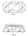
- Figures 1 and 2 show a light assembly comprising a pair of light-emitting diodes (LEDs) arranged at one end of the assembly.
- LEDs light-emitting diodes
- Circuitry 4 is provided to allow recharging of the solar cell 2 to energize the LEDs 3.
- the assembly is encapsulated in potting resins 6 within a protective shell 7.
- Figure 3 shows a circuit in which the solar cell directly charges four supercapacitors C1-C4 via blocking diode D3, which prevents discharge of said capacitors back through solar cell during darkness.
- Zener diode D4 prevents overcharging of the capacitors, limiting charge to 5.6 volts.
- the pulse rate and pulse duration of the two LED lights is controlled by the astable multivibrator consisting of transistors Q2 and Q3, capacitors C5 and C6, and associated resistors.
- Q1 is the driver transistor for the LEDs.
- Light sensitive switch circuitry is provided by transistor Q4 and resistors R8 and R9 which are driven by the solar cell. This circuitry enables use of the solar cell as a photosensor which selectively energizes the LEDs when ambient light is below a pre-determined level. The circuitry also stops energizing of the LEDs when the ambient light is above a pre-determined level and enables charging of the capacitors by the solar cell. The circuitry therefore ensures that, at night, the LEDs turn on powered by the capacitors, and that during the day, the LEDs are turned off and the capacitors are recharged. There is no requirement for any physical switch on the light assembly.
- This circuitry uses a solar panel with sufficiently high voltage output that no step-up voltage conversion is required to charge the capacitors fully. This avoids the additional power requirements and loss of reliability incurred by using a step-up voltage converter. Similarly, no voltage conversion or stabilization is required to drive the LEDs. The energy stored in the capacitors is used to directly drive the LEDs, which is possible since LEDs are designed to operate over a wide voltage range. The elimination of voltage conversion and stabilization circuitry avoids expense, potential component failure, and power loss.
- the manufacture of the light assembly includes means to mount the assembly.
- acorn nuts 5 are placed in the potting compound to provide for bolt mounting of the assembly.
- Other means of mounting can include a bolt or screw placed in the potting compound, an adhesive pad mounted to the bottom of the assembly, or gluing/epoxying of the light assembly to a surface. Since no servicing of the light assembly is required, the mounting of the light assembly may be permanent.
- a reflective layer may be included in the light assembly to facilitate its use as a road marker.
- the potting compounds 6 may be any appropriate potting compounds suitable for potting electronic components, providing of course, that the layer above the solar panel and adjacent to the LEDs is transparent. Potting compounds may include epoxy, polyester or silicone compounds. The potting compounds may be set in a plastic casing or may be gel-coated to provide protection from ultraviolet radiation and from impact. This light assembly is intended to be used in a broad variety of applications and as such, the LEDs may be yellow and/or red for use in marine environments to mark starboard and port. In applications where maximum range of the light is desired, the LEDs may protrude from the housings. The LEDs may be located at one end of the assembly for unidirectional marking, such as on roads, or may be bi-directional or circular. In order to achieve 360 degree visibility, a light diffuser may be included in the assembly.
- the device is sufficiently small and durable that it can be used in the centre of highways where the ubiquitous catseye is presently used, either to mark lanes or to indicate crosswalks or other significant features.
Landscapes
- Engineering & Computer Science (AREA)
- General Engineering & Computer Science (AREA)
- Physics & Mathematics (AREA)
- Civil Engineering (AREA)
- Electromagnetism (AREA)
- General Physics & Mathematics (AREA)
- Architecture (AREA)
- Life Sciences & Earth Sciences (AREA)
- Structural Engineering (AREA)
- Sustainable Development (AREA)
- Illuminated Signs And Luminous Advertising (AREA)
- Polarising Elements (AREA)
- Vehicle Body Suspensions (AREA)
- Seal Device For Vehicle (AREA)
- Charge And Discharge Circuits For Batteries Or The Like (AREA)
- Led Devices (AREA)
- Non-Portable Lighting Devices Or Systems Thereof (AREA)
Abstract
Description
- This invention relates to a light assembly.
- Provision of hazard or marker lighting in remote areas such as parks, trails, floating docks, temporary airstrips and logging roads is very expensive with standard technology. Even hazard lights on highways are expensive to install, with the result that hazard marking on highways is usually done with reflectors instead of lights.
- The key limitation of traditional technology is that electricity must be provided to the hazard/marker lights, and in locations remote from power lines, provision of electricity is prohibitively expensive. Solar panels have provided an independent power source that allows hazard/marker lighting to be installed in some of these locations. However, solar installations have not been particularly widespread due to the costs involved in the installation and maintenance, problems with battery systems, and the susceptibility of the lighting assembly to vandalism.
- In U.S. patent 4,050,834, Lee describes an advance in which light-emitting diodes (LEDs) are used to replace standard light bulbs in a solar-powered light assembly to make a lane marker for traffic. Because of their excellent power efficiency and durability, the use of LEDs greatly reduces the size and cost of a solar light assembly. However, Lee's light assembly still requires the use of a battery as a means of energy storage to power the light at night when the solar panel is not producing electricity. The use of a rechargeable battery poses considerable limitations on the light assembly. Rechargeable batteries last only 1-2 years, and then require replacement. This means the light assembly must be removable and have a battery compartment, and that regular servicing is scheduled. A removable light with a battery compartment is vandal-prone, and the cost of battery replacement and disposal is unattractive, with the result that the Lee invention has not been commercially successful.
- U.S. patent 4,634,953 to Shoji et al describes a solar-powered watch in which capacitors (or supercapacitors as they are commonly known) are used as the energy storage means instead of batteries. Capacitors offer the advantage that they are durable and do not require servicing: they can be expected to last for decades. The disadvantages of capacitors include the requirement that they must be charged to a relatively high voltage compared to a battery (typically 5.5 volts), and the fact that the voltage which is supplied by the capacitor to the load is not stable like a battery, but declines exponentially to zero. Shoji et al describe two voltage regulators to overcome these problems, one which increases the voltage generated by the solar panel, and the other which stabilizes the voltage which is produced by the capacitor so that it can be used to run electronics such as a watch.
- The present invention capitalizes on the strengths of LED and capacitor technologies, but does not require either of the voltage converters described by Shoji et al. The resulting light assembly is a device of striking simplicity, power efficiency, and durability which is not prone to vandalism, and which requires no servicing for periods measured in decades.
- Accordingly, the present invention is a light assembly comprising a light-emitting diode (LED), a capacitor to energize said LED, a solar cell to charge the capacitor and circuitry which enables the assembly to flash for several hours after solar illumination has ceased characterized by circuitry to enable use of the solar cell as a photosensor to selectively enable energizing of the LED when the ambient light is below a pre-determined level, and to stop energizing the LED when the ambient light is above a pre-determined level.
- In a particularly desirable aspect, the light assembly is housed in a plexiglass shell and potted with appropriate potting compounds. Potting techniques are known, particularly for small electronic components. The light assembly of the present invention is designed for potting and this assists in enhancing the durability and vandal-proof nature of the device.
- When potted, the LED may protrude from the assembly or the complete light assembly may be embedded within the potting compounds.
- The invention is illustrated in the drawings in which:
- Figure 1 is a plan view of the light assembly according to the present invention;
- Figure 2 is a side elevation of the assembly of Figure 1;
- Figure 3 is a circuit diagram of the invention.
-
- Figures 1 and 2 show a light assembly comprising a pair of light-emitting diodes (LEDs) arranged at one end of the assembly. There are rechargeable capacitors 1 to energize the
LEDs 3 and asolar cell 2 for recharging the capacitors 1.Circuitry 4 is provided to allow recharging of thesolar cell 2 to energize theLEDs 3. The assembly is encapsulated inpotting resins 6 within a protective shell 7. - Figure 3 shows a circuit in which the solar cell directly charges four supercapacitors C1-C4 via blocking diode D3, which prevents discharge of said capacitors back through solar cell during darkness. Zener diode D4 prevents overcharging of the capacitors, limiting charge to 5.6 volts. The pulse rate and pulse duration of the two LED lights is controlled by the astable multivibrator consisting of transistors Q2 and Q3, capacitors C5 and C6, and associated resistors. Q1 is the driver transistor for the LEDs.
- Light sensitive switch circuitry is provided by transistor Q4 and resistors R8 and R9 which are driven by the solar cell. This circuitry enables use of the solar cell as a photosensor which selectively energizes the LEDs when ambient light is below a pre-determined level. The circuitry also stops energizing of the LEDs when the ambient light is above a pre-determined level and enables charging of the capacitors by the solar cell.
The circuitry therefore ensures that, at night, the LEDs turn on powered by the capacitors, and that during the day, the LEDs are turned off and the capacitors are recharged. There is no requirement for any physical switch on the light assembly. - This circuitry uses a solar panel with sufficiently high voltage output that no step-up voltage conversion is required to charge the capacitors fully. This avoids the additional power requirements and loss of reliability incurred by using a step-up voltage converter.
Similarly, no voltage conversion or stabilization is required to drive the LEDs. The energy stored in the capacitors is used to directly drive the LEDs, which is possible since LEDs are designed to operate over a wide voltage range. The elimination of voltage conversion and stabilization circuitry avoids expense, potential component failure, and power loss. - The manufacture of the light assembly includes means to mount the assembly. In the preferred embodiment,
acorn nuts 5 are placed in the potting compound to provide for bolt mounting of the assembly. Other means of mounting can include a bolt or screw placed in the potting compound, an adhesive pad mounted to the bottom of the assembly, or gluing/epoxying of the light assembly to a surface. Since no servicing of the light assembly is required, the mounting of the light assembly may be permanent. - A reflective layer may be included in the light assembly to facilitate its use as a road marker.
- The
potting compounds 6 may be any appropriate potting compounds suitable for potting electronic components, providing of course, that the layer above the solar panel and adjacent to the LEDs is transparent. Potting compounds may include epoxy, polyester or silicone compounds. The potting compounds may be set in a plastic casing or may be gel-coated to provide protection from ultraviolet radiation and from impact. This light assembly is intended to be used in a broad variety of applications and as such, the LEDs may be yellow and/or red for use in marine environments to mark starboard and port. In applications where maximum range of the light is desired, the LEDs may protrude from the housings. The LEDs may be located at one end of the assembly for unidirectional marking, such as on roads, or may be bi-directional or circular. In order to achieve 360 degree visibility, a light diffuser may be included in the assembly. - The device is sufficiently small and durable that it can be used in the centre of highways where the ubiquitous catseye is presently used, either to mark lanes or to indicate crosswalks or other significant features.
- The simplicity, durability, and vandal-resistance of the design is believed to be of major significance in providing hazard or marker lighting for a broad range of applications. It is envisaged that decades of use can be obtained from a single light assembly.
- Although the foregoing invention has been described in some detail by way of illustration and example for purposes of clarity of understanding, it will be readily apparent to those of ordinary skill in the art that, in the light of the teachings of this invention, certain changes and modifications may be made thereto without departing from the scope of the appended claims.
Claims (9)
- A light assembly comprising:a light-emitting diode (LED) (3);a rechargeable capacitor (1) to energize said LED (3) ;a solar cell (2) to recharge the capacitor (1) and circuitry (4) to enable recharging of the capacitor (1) and to enable the LED (3) to flash for several hours after solar illumination has ceased characterized by circuitry (D3, D4, Q4, Q8, Q9) to enable use of the solar cell as a photosensor to selectively energize the LED when the ambient light is below a pre-determined level, to stop energizing the LED when the ambient light is above a pre-determined level, and to enable charging of the capacitor by the solar cell when the ambient light is above a pre-determined level.
- A light assembly as claimed in claim 1,
characterized by circuitry (Q2, Q3) to enable pulsing of the LED (3). - A light assembly as claimed in claim 2,
characterized by the assembly being potted in various potting compounds (6). - A light assembly as claimed in claim 3,
characterized by the LED (3) protruding from the potting compounds (6). - A light assembly as claimed in claim 4,
characterized by the LED (3) being completely embedded within the potting compounds (6). - A light assembly as claimed in claim 5,
characterized by the potting compound (6) being selected from one or more of epoxy, polyester, or silicone compounds. - A light assembly as claimed in claim 4,
characterized by the light assembly being embedded in potting compound (6) and encased in an acrylic or polycarbonate transparent housing (7). - A light assembly as claimed in claim 1,
characterized by a plurality of LEDs (3), capacitors (1), and solar cells (2). - A light assembly as claimed in claim 1,
characterized by means (5) to mount the assembly to a surface.
Applications Claiming Priority (3)
| Application Number | Priority Date | Filing Date | Title |
|---|---|---|---|
| US506750 | 1990-04-09 | ||
| US08/506,750 US5782552A (en) | 1995-07-26 | 1995-07-26 | Light assembly |
| PCT/CA1996/000525 WO1997005422A1 (en) | 1995-07-26 | 1996-07-25 | A light assembly |
Publications (2)
| Publication Number | Publication Date |
|---|---|
| EP0851989A1 EP0851989A1 (en) | 1998-07-08 |
| EP0851989B1 true EP0851989B1 (en) | 2000-09-27 |
Family
ID=24015872
Family Applications (1)
| Application Number | Title | Priority Date | Filing Date |
|---|---|---|---|
| EP96925627A Expired - Lifetime EP0851989B1 (en) | 1995-07-26 | 1996-07-25 | A light assembly |
Country Status (6)
| Country | Link |
|---|---|
| US (1) | US5782552A (en) |
| EP (1) | EP0851989B1 (en) |
| AT (1) | ATE196678T1 (en) |
| AU (1) | AU6609496A (en) |
| DE (1) | DE69610504T2 (en) |
| WO (1) | WO1997005422A1 (en) |
Families Citing this family (98)
| Publication number | Priority date | Publication date | Assignee | Title |
|---|---|---|---|---|
| US6200134B1 (en) | 1998-01-20 | 2001-03-13 | Kerr Corporation | Apparatus and method for curing materials with radiation |
| US6013985A (en) * | 1998-04-23 | 2000-01-11 | Carmanah Technologies Ltd. | Sealed solar-powered light assembly |
| US6160353A (en) * | 1998-06-18 | 2000-12-12 | Mancuso; Michael L. | Remote positionable photocell device for use with an exterior landscape lighting assembly |
| AT407603B (en) * | 1998-08-27 | 2001-05-25 | Schletterer Georg | LUMINOUS DRINKING GLASSES, DRINKING CUPS AND BOTTLES |
| US6086220A (en) * | 1998-09-30 | 2000-07-11 | Lash International Inc. | Marine safety light |
| FR2790060B1 (en) * | 1999-02-23 | 2002-01-04 | Roger Durand | SIGNALING DEVICE FOR AIDING TRAFFIC AT NIGHT OR IN BAD WEATHER |
| WO2000060277A1 (en) * | 1999-04-03 | 2000-10-12 | Buenting Gerd | Signalling light with light-emitting diode |
| EP1076477A3 (en) * | 1999-08-13 | 2002-04-17 | Tai-Her Yang | Solar cell for lighting purpose |
| US6676279B1 (en) * | 1999-10-04 | 2004-01-13 | David A. Hubbell | Area lighting device using discrete light sources, such as LEDs |
| WO2001061112A1 (en) * | 2000-02-17 | 2001-08-23 | Sekisui Jushi Kabushiki Kaisha | Road sign device and spontaneously emitted light sign system used for the device |
| US6573659B2 (en) | 2000-03-31 | 2003-06-03 | Carmanah Technologies, Inc. | Solar-powered light assembly with automatic light control |
| WO2002086977A1 (en) * | 2001-04-23 | 2002-10-31 | Carmanah Technologies Inc. | Potted domed solar panel capsule and traffic warning lamps incorporating same |
| US7242313B2 (en) * | 2001-07-26 | 2007-07-10 | Harwood Ronald P | System for providing pathway indications through unlit areas |
| US6778093B2 (en) * | 2001-07-26 | 2004-08-17 | Ronald P. Harwood | System for providing pathway indications through unit areas |
| AUPR725301A0 (en) * | 2001-08-24 | 2001-09-20 | Jones, Darryl John | Lighting apparatus |
| US7048423B2 (en) * | 2001-09-28 | 2006-05-23 | Visteon Global Technologies, Inc. | Integrated light and accessory assembly |
| US6602021B1 (en) * | 2002-01-14 | 2003-08-05 | Kwung-Chul Kim | Pavement marker and method for manufacturing the same |
| US6685334B2 (en) | 2002-04-30 | 2004-02-03 | G-5 Electronics | System and method of power management for a solar powered device |
| US7167103B2 (en) * | 2002-06-13 | 2007-01-23 | Warren Bradford S | Transport node apparatus |
| WO2004029919A1 (en) * | 2002-09-24 | 2004-04-08 | Carmanah Technologies Inc. | Solar-powered bus stop |
| ITPR20020055A1 (en) * | 2002-10-16 | 2004-04-17 | Lorenzo Schia | GROUND PAINTED SIGNAGE LIGHTING SYSTEM, IN PARTICULAR ROAD SIGNAGE |
| US7490957B2 (en) * | 2002-11-19 | 2009-02-17 | Denovo Lighting, L.L.C. | Power controls with photosensor for tube mounted LEDs with ballast |
| US20040139999A1 (en) * | 2002-12-16 | 2004-07-22 | Romo Luis Manuel | Solar powered (photovoltaic) electro luminescent extruded lighting device |
| US20040226601A1 (en) * | 2003-02-24 | 2004-11-18 | Mark Banister | Photovoltaic/solar safety and marker tape |
| US20040175232A1 (en) * | 2003-03-07 | 2004-09-09 | Hunter Charles Eric | Emissive highway markers |
| US7387400B2 (en) * | 2003-04-21 | 2008-06-17 | Kyosemi Corporation | Light-emitting device with spherical photoelectric converting element |
| WO2005008260A1 (en) * | 2003-07-22 | 2005-01-27 | Icp Global Technologies Inc. | Solar panel having visual indicator |
| FR2858905B1 (en) * | 2003-08-12 | 2006-03-31 | Roger Tiburce Louis Durand | DEVICE FOR SUPPLYING LIGHT SOURCES BY DISCHARGE CAPACITORS |
| ITMI20031752A1 (en) * | 2003-09-12 | 2005-03-13 | Giuseppe Lombardi | LUMINOUS TILE WITH SOLAR POWER SUPPLY. |
| US7688222B2 (en) | 2003-09-18 | 2010-03-30 | Spot Devices, Inc. | Methods, systems and devices related to road mounted indicators for providing visual indications to approaching traffic |
| DE10361982B4 (en) * | 2003-12-30 | 2015-07-16 | Airbus Operations Gmbh | Emergency lighting arrangement for an aircraft |
| US20050238425A1 (en) * | 2004-04-22 | 2005-10-27 | Safar Samir H | Pavement marker and system for freeway advance accident merge signal |
| US7018131B2 (en) * | 2004-04-28 | 2006-03-28 | Jordan Wesley B | Long life intelligent illuminated road marker |
| US20080030978A1 (en) * | 2004-07-23 | 2008-02-07 | Hume Stuart J | Stud for Roads |
| US7259692B1 (en) * | 2004-09-01 | 2007-08-21 | The United States Of America As Represented By The Administrator Of Nasa | Hybrid power management system and method |
| US7044616B2 (en) * | 2004-09-13 | 2006-05-16 | Yi Cyuan Shih | Solar powered warning light device |
| US20060087851A1 (en) * | 2004-10-13 | 2006-04-27 | Dubord Jack G | Encasing for light circuit |
| US20080174989A1 (en) * | 2004-10-22 | 2008-07-24 | Mark Robinett | Rechargeable Portable Light with Multiple Charging Systems |
| US7323849B1 (en) * | 2004-10-22 | 2008-01-29 | Robinett Mark I | Rechargeable portable light with multiple charging systems |
| US7401508B1 (en) * | 2004-10-28 | 2008-07-22 | Peterson George W | Illuminated rain gauge |
| US7152468B1 (en) | 2004-10-28 | 2006-12-26 | Garner Industries, Inc. | Illuminated rain gauge |
| US7536907B1 (en) * | 2004-10-28 | 2009-05-26 | Peterson George W | Illuminated rain gauge |
| US20060102225A1 (en) * | 2004-11-12 | 2006-05-18 | Chih-Pang Chou | Base assembly having a plurality of solar powered illuminators for simultaneously illumination |
| US20060257204A1 (en) * | 2005-05-13 | 2006-11-16 | Hye Lites Industries, Llc | Wireless reflective marker with internal light source |
| US20060278816A1 (en) * | 2005-06-09 | 2006-12-14 | Booty Donald J | Portable mountable indoor lamp having a positionable lamp head and motion and light sensors which can be aimed |
| US9657909B2 (en) | 2005-06-23 | 2017-05-23 | Rsr Sales, Inc. | Self-contained, solar-powered LED illuminator modules and applications thereof |
| US20110292644A1 (en) * | 2005-06-23 | 2011-12-01 | Richard Cohen | Apparatus and method for converting gazing globes and other decorative objects into glow-in-the-dark products |
| US20070034249A1 (en) * | 2005-08-12 | 2007-02-15 | Romano Matthew A | Floating solar powered electronic device and system |
| US20070034248A1 (en) * | 2005-08-12 | 2007-02-15 | Romano Matthew A | Floating solar powered lighting apparatus, system and ladder accessory |
| US7525424B2 (en) * | 2006-08-15 | 2009-04-28 | Patented Technology Incorporated | Illuminated trail marker apparatus |
| US7740177B2 (en) * | 2006-10-20 | 2010-06-22 | Exhart Environmental Systems, Inc. | Solar light stick |
| US8002427B2 (en) * | 2007-01-12 | 2011-08-23 | Candew Scientific, Llc | Solar rechargeable light emitting diode lights |
| ITMI20070453A1 (en) * | 2007-03-07 | 2008-09-08 | Korotek S R L | METHOD AND DEVICE FOR AUTHENTICATION OF THE IDENTITY IN WHICH IT IS POSSIBLE TO GENERATE ACESS CODES BY USING THROUGH THE DECODING OF IMAGES WHERE THE LIGHT IS ALSO USED FOR THE SUPPLY OF THE SAME DEVICE |
| US8231240B1 (en) * | 2007-12-12 | 2012-07-31 | Txl Group, Inc. | Surface lighting devices having a thermoelectric power source |
| US7883234B2 (en) * | 2008-04-18 | 2011-02-08 | Spot Devices, Inc | Embeddable lighting systems |
| US20100027248A1 (en) * | 2008-07-29 | 2010-02-04 | Kao-Hsung Tsung | Solar Lamp |
| CN201255348Y (en) * | 2008-09-11 | 2009-06-10 | 陈建国 | Solar LED lamp indicator sign |
| US20100271815A1 (en) * | 2008-10-24 | 2010-10-28 | Lights International Group, Inc. | Clip-on decorative led light |
| US7887214B2 (en) * | 2009-01-22 | 2011-02-15 | Sunny General International Co., Ltd. | Solar LED lamp |
| US9066777B2 (en) | 2009-04-02 | 2015-06-30 | Kerr Corporation | Curing light device |
| US9072572B2 (en) | 2009-04-02 | 2015-07-07 | Kerr Corporation | Dental light device |
| CN101900286A (en) * | 2009-05-27 | 2010-12-01 | 富士迈半导体精密工业(上海)有限公司 | An anti-glare road lighting device |
| US7994735B1 (en) | 2009-07-22 | 2011-08-09 | Berman Amy S | Solar-controlled light device |
| RS53023B (en) | 2009-09-07 | 2014-04-30 | Rt-Rk Za Sisteme Zasnovane Na Raäśunarima D.O.O. | System for marking road edge in low visibility conditions using wirelessly coupled signalling devices |
| US20110157879A1 (en) * | 2009-12-29 | 2011-06-30 | Du Pont Apollo Ltd. | Light assembly and method of manufacturing the same |
| US20110168501A1 (en) * | 2010-01-08 | 2011-07-14 | Henry Stephen K | Wheel chock with solar-powered lights |
| US11248755B2 (en) | 2010-06-18 | 2022-02-15 | Luminaid Lab, Llc | Inflatable solar-powered light |
| GB201010249D0 (en) * | 2010-06-18 | 2010-07-21 | Clearview Traffic Group Ltd | Road stud |
| US8414153B2 (en) | 2010-08-05 | 2013-04-09 | Access 2 Communications, Inc. | High powered universal LED lamp |
| DE102010040398A1 (en) | 2010-09-08 | 2012-03-08 | Tridonic Gmbh & Co. Kg | Improvement of the energy efficiency of at least one light source having lighting system and corresponding lighting system |
| US8632207B2 (en) * | 2010-11-05 | 2014-01-21 | Lex Products Corporation | LED lighting apparatus and housing |
| AU2012378999A1 (en) | 2012-05-01 | 2014-12-18 | Luminaid Lab, Llc | Inflatable solar-powered light |
| CN102878462B (en) * | 2012-09-26 | 2014-11-26 | 杭州赛源照明电器有限公司 | lighting fixtures |
| US9016886B2 (en) * | 2012-11-01 | 2015-04-28 | Mpowerd, Inc. | Inflatable solar powered lamp |
| JP6201360B2 (en) * | 2013-03-22 | 2017-09-27 | 東芝ライテック株式会社 | Lighting power supply and lighting device |
| US9399844B1 (en) | 2014-01-13 | 2016-07-26 | Evolutionary Markings, Inc. | Pavement marker modules |
| USD709438S1 (en) | 2014-01-17 | 2014-07-22 | Gordon Ko | Central solar panel stepping stone |
| ES1108058Y (en) * | 2014-03-12 | 2014-07-22 | Rios Juan Rosado | Submersible Solar Lighting System |
| US9388953B2 (en) * | 2014-07-30 | 2016-07-12 | Goal Zero Llc | Solar powered flashlight |
| US9080736B1 (en) | 2015-01-22 | 2015-07-14 | Mpowerd Inc. | Portable solar-powered devices |
| US20160276555A1 (en) * | 2015-03-18 | 2016-09-22 | Toyoda Gosei Co., Ltd. | Light emitting device manufacturing method and light emitting device |
| US10808898B2 (en) * | 2015-03-26 | 2020-10-20 | Tiger Tech Industries | Solar powered light assembly with sensor |
| USD932078S1 (en) | 2015-07-14 | 2021-09-28 | Luminaid Lab, Llc | Expandable light |
| US10259381B2 (en) * | 2016-03-07 | 2019-04-16 | Kwang J. Oh | LED light bar cover with auto shut off light switch |
| CN205807211U (en) * | 2016-06-20 | 2016-12-14 | 冯霞 | Light-emitting device for container |
| CN106245551B (en) * | 2016-08-26 | 2018-10-19 | 青岛大学 | A kind of portable intelligent traffic sign blanket |
| US10760746B2 (en) | 2016-11-04 | 2020-09-01 | Luminaid Lab, Llc | Solar lamp with radial elements and electronics assembly contained in a watertight enclosure |
| US10514140B2 (en) | 2016-11-04 | 2019-12-24 | Luminaid Lab, Llc | Multi-powering solar lamps |
| ES2659433A1 (en) * | 2017-04-11 | 2018-03-15 | Juan Rosado Rios | Improvement of submersible solar lighting system (Machine-translation by Google Translate, not legally binding) |
| US10480138B2 (en) | 2017-06-05 | 2019-11-19 | David E. Lambert | Illuminated road marker |
| WO2019023371A1 (en) | 2017-07-26 | 2019-01-31 | Lambert David E | Reflective road marker |
| RU185134U1 (en) * | 2017-11-07 | 2018-11-22 | Общество с ограниченной ответственностью "ЕХ-ПРИБОР" | Explosion-proof light board |
| US10180221B1 (en) | 2018-02-12 | 2019-01-15 | Mpowerd Inc. | Modular solar-powered lighting devices and components thereof |
| US10851502B2 (en) | 2018-06-20 | 2020-12-01 | Smart Safety Marker, LLC | Solar powered illuminated safety marker and improved housing therefor |
| US10704746B2 (en) | 2018-10-19 | 2020-07-07 | Mpowerd Inc. | Portable lighting devices with wireless connectivity |
| US11632848B2 (en) | 2019-06-03 | 2023-04-18 | Pauly Enterprises, LLC | Interconnected remote control lighting system |
| USD973948S1 (en) | 2020-05-01 | 2022-12-27 | Craig A. Homic | Dock light |
| US12038151B2 (en) | 2021-07-12 | 2024-07-16 | Alice Chun | Collapsible and expandable portable lamp and solar-charging battery assembly |
Family Cites Families (13)
| Publication number | Priority date | Publication date | Assignee | Title |
|---|---|---|---|---|
| US2700754A (en) * | 1951-05-03 | 1955-01-25 | Mccullough Joseph | Armored illuminated highway marker |
| GB1490978A (en) * | 1973-12-21 | 1977-11-09 | Marconi Co Ltd | Light emitting diode(led)arrays |
| US4050834A (en) * | 1976-02-04 | 1977-09-27 | Minnesota Mining And Manufacturing Company | Internally powered traffic control device |
| GB2039936A (en) * | 1979-01-22 | 1980-08-20 | Watkins D | Marker lamps |
| US4634953A (en) * | 1984-04-27 | 1987-01-06 | Casio Computer Co., Ltd. | Electronic equipment with solar cell |
| US4603496A (en) * | 1985-02-04 | 1986-08-05 | Adaptive Micro Systems, Inc. | Electronic display with lens matrix |
| US4959603A (en) * | 1987-10-27 | 1990-09-25 | Osaka Titanium Co., Ltd. | Solar battery equipment |
| US4843280A (en) * | 1988-01-15 | 1989-06-27 | Siemens Corporate Research & Support, Inc. | A modular surface mount component for an electrical device or led's |
| DE4001980A1 (en) * | 1989-02-03 | 1990-08-09 | Albrecht H Sinnigen | Marking stud for road surfaces - has head with surface directed upwards provided with solar cells and light-responsive sensor switch |
| US5262756A (en) * | 1991-03-15 | 1993-11-16 | Chien Tseng L | Solar powered warning light |
| IL98755A (en) * | 1991-07-08 | 1996-01-19 | Chacham Chaim | Led electronic flasher circuit |
| UA41260C2 (en) * | 1992-07-08 | 2001-09-17 | Astucia Lda | |
| JPH07277246A (en) * | 1994-04-13 | 1995-10-24 | Elna Co Ltd | Safety marker light |
-
1995
- 1995-07-26 US US08/506,750 patent/US5782552A/en not_active Expired - Lifetime
-
1996
- 1996-07-25 EP EP96925627A patent/EP0851989B1/en not_active Expired - Lifetime
- 1996-07-25 AU AU66094/96A patent/AU6609496A/en not_active Abandoned
- 1996-07-25 AT AT96925627T patent/ATE196678T1/en active
- 1996-07-25 DE DE69610504T patent/DE69610504T2/en not_active Expired - Lifetime
- 1996-07-25 WO PCT/CA1996/000525 patent/WO1997005422A1/en not_active Ceased
Also Published As
| Publication number | Publication date |
|---|---|
| US5782552A (en) | 1998-07-21 |
| EP0851989A1 (en) | 1998-07-08 |
| WO1997005422A1 (en) | 1997-02-13 |
| DE69610504T2 (en) | 2001-06-07 |
| DE69610504D1 (en) | 2000-11-02 |
| AU6609496A (en) | 1997-02-26 |
| ATE196678T1 (en) | 2000-10-15 |
Similar Documents
| Publication | Publication Date | Title |
|---|---|---|
| US5782552A (en) | Light assembly | |
| US4843525A (en) | Solar powered yard marker | |
| US7794103B2 (en) | Parking space barrier block with photovoltaic illumination | |
| CN203807975U (en) | Road markings or light-based warning devices | |
| CA2241044C (en) | Sealed solar-powered light assembly | |
| US7018131B2 (en) | Long life intelligent illuminated road marker | |
| US20080232094A1 (en) | Solar powered post lamp | |
| WO1987002400A1 (en) | Solar-powered illuminated reflector | |
| US20080272278A1 (en) | Solar Powered Light | |
| EP1818605B1 (en) | Light signaling post | |
| IL98755A (en) | Led electronic flasher circuit | |
| US10989379B2 (en) | Lighted piling cap | |
| CN1260696C (en) | Half mirror reflector having led road sign | |
| US20210198854A1 (en) | Solar Powered Illuminated Safety marker and Improved Housing Therefor | |
| KR20100110974A (en) | Cognition device for bollard | |
| JPH04203109A (en) | Luminous type pavement unit, paving stone and paving method | |
| KR102724875B1 (en) | Sola And Wind Delineator | |
| KR200454393Y1 (en) | UV excitation self surface emitting delineator | |
| GB2403499A (en) | Solar powered illuminated bollard | |
| CN108109546A (en) | Modular solar power noctilucence direction board | |
| CN109285384B (en) | Parking space indicating lamp group | |
| EP1515087A2 (en) | Luminous sun fed brick | |
| CN218060019U (en) | Solar energy reflection of light warning post | |
| KR200302563Y1 (en) | Pavement Light Block | |
| CN2421317Y (en) | Solar self-lighting type raised road sign |
Legal Events
| Date | Code | Title | Description |
|---|---|---|---|
| PUAI | Public reference made under article 153(3) epc to a published international application that has entered the european phase |
Free format text: ORIGINAL CODE: 0009012 |
|
| 17P | Request for examination filed |
Effective date: 19980506 |
|
| AK | Designated contracting states |
Kind code of ref document: A1 Designated state(s): AT BE CH DE DK ES FI FR GB GR IE IT LI LU MC NL PT SE |
|
| GRAG | Despatch of communication of intention to grant |
Free format text: ORIGINAL CODE: EPIDOS AGRA |
|
| 17Q | First examination report despatched |
Effective date: 19991123 |
|
| GRAG | Despatch of communication of intention to grant |
Free format text: ORIGINAL CODE: EPIDOS AGRA |
|
| GRAH | Despatch of communication of intention to grant a patent |
Free format text: ORIGINAL CODE: EPIDOS IGRA |
|
| RIC1 | Information provided on ipc code assigned before grant |
Free format text: 7F 21K 7/00 A, 7H 05B 37/00 B |
|
| GRAH | Despatch of communication of intention to grant a patent |
Free format text: ORIGINAL CODE: EPIDOS IGRA |
|
| GRAA | (expected) grant |
Free format text: ORIGINAL CODE: 0009210 |
|
| AK | Designated contracting states |
Kind code of ref document: B1 Designated state(s): AT BE CH DE DK ES FI FR GB GR IE IT LI LU MC NL PT SE |
|
| PG25 | Lapsed in a contracting state [announced via postgrant information from national office to epo] |
Ref country code: NL Free format text: LAPSE BECAUSE OF FAILURE TO SUBMIT A TRANSLATION OF THE DESCRIPTION OR TO PAY THE FEE WITHIN THE PRESCRIBED TIME-LIMIT Effective date: 20000927 Ref country code: LI Free format text: LAPSE BECAUSE OF FAILURE TO SUBMIT A TRANSLATION OF THE DESCRIPTION OR TO PAY THE FEE WITHIN THE PRESCRIBED TIME-LIMIT Effective date: 20000927 Ref country code: FI Free format text: LAPSE BECAUSE OF FAILURE TO SUBMIT A TRANSLATION OF THE DESCRIPTION OR TO PAY THE FEE WITHIN THE PRESCRIBED TIME-LIMIT Effective date: 20000927 Ref country code: ES Free format text: THE PATENT HAS BEEN ANNULLED BY A DECISION OF A NATIONAL AUTHORITY Effective date: 20000927 Ref country code: CH Free format text: LAPSE BECAUSE OF FAILURE TO SUBMIT A TRANSLATION OF THE DESCRIPTION OR TO PAY THE FEE WITHIN THE PRESCRIBED TIME-LIMIT Effective date: 20000927 Ref country code: BE Free format text: LAPSE BECAUSE OF FAILURE TO SUBMIT A TRANSLATION OF THE DESCRIPTION OR TO PAY THE FEE WITHIN THE PRESCRIBED TIME-LIMIT Effective date: 20000927 Ref country code: AT Free format text: LAPSE BECAUSE OF FAILURE TO SUBMIT A TRANSLATION OF THE DESCRIPTION OR TO PAY THE FEE WITHIN THE PRESCRIBED TIME-LIMIT Effective date: 20000927 |
|
| REF | Corresponds to: |
Ref document number: 196678 Country of ref document: AT Date of ref document: 20001015 Kind code of ref document: T |
|
| REG | Reference to a national code |
Ref country code: CH Ref legal event code: EP |
|
| REG | Reference to a national code |
Ref country code: IE Ref legal event code: FG4D |
|
| REF | Corresponds to: |
Ref document number: 69610504 Country of ref document: DE Date of ref document: 20001102 |
|
| ITF | It: translation for a ep patent filed | ||
| PG25 | Lapsed in a contracting state [announced via postgrant information from national office to epo] |
Ref country code: SE Free format text: LAPSE BECAUSE OF FAILURE TO SUBMIT A TRANSLATION OF THE DESCRIPTION OR TO PAY THE FEE WITHIN THE PRESCRIBED TIME-LIMIT Effective date: 20001227 Ref country code: PT Free format text: LAPSE BECAUSE OF FAILURE TO SUBMIT A TRANSLATION OF THE DESCRIPTION OR TO PAY THE FEE WITHIN THE PRESCRIBED TIME-LIMIT Effective date: 20001227 Ref country code: DK Free format text: LAPSE BECAUSE OF FAILURE TO SUBMIT A TRANSLATION OF THE DESCRIPTION OR TO PAY THE FEE WITHIN THE PRESCRIBED TIME-LIMIT Effective date: 20001227 |
|
| PG25 | Lapsed in a contracting state [announced via postgrant information from national office to epo] |
Ref country code: GR Free format text: LAPSE BECAUSE OF FAILURE TO SUBMIT A TRANSLATION OF THE DESCRIPTION OR TO PAY THE FEE WITHIN THE PRESCRIBED TIME-LIMIT Effective date: 20001229 |
|
| ET | Fr: translation filed | ||
| NLV1 | Nl: lapsed or annulled due to failure to fulfill the requirements of art. 29p and 29m of the patents act | ||
| REG | Reference to a national code |
Ref country code: CH Ref legal event code: PL |
|
| PG25 | Lapsed in a contracting state [announced via postgrant information from national office to epo] |
Ref country code: LU Free format text: LAPSE BECAUSE OF NON-PAYMENT OF DUE FEES Effective date: 20010725 Ref country code: IE Free format text: LAPSE BECAUSE OF NON-PAYMENT OF DUE FEES Effective date: 20010725 |
|
| PLBE | No opposition filed within time limit |
Free format text: ORIGINAL CODE: 0009261 |
|
| STAA | Information on the status of an ep patent application or granted ep patent |
Free format text: STATUS: NO OPPOSITION FILED WITHIN TIME LIMIT |
|
| 26N | No opposition filed | ||
| REG | Reference to a national code |
Ref country code: GB Ref legal event code: IF02 |
|
| PG25 | Lapsed in a contracting state [announced via postgrant information from national office to epo] |
Ref country code: MC Free format text: LAPSE BECAUSE OF NON-PAYMENT OF DUE FEES Effective date: 20020201 |
|
| REG | Reference to a national code |
Ref country code: IE Ref legal event code: MM4A |
|
| PGFP | Annual fee paid to national office [announced via postgrant information from national office to epo] |
Ref country code: DE Payment date: 20110826 Year of fee payment: 16 Ref country code: FR Payment date: 20110811 Year of fee payment: 16 Ref country code: GB Payment date: 20110801 Year of fee payment: 16 |
|
| PGFP | Annual fee paid to national office [announced via postgrant information from national office to epo] |
Ref country code: IT Payment date: 20110801 Year of fee payment: 16 |
|
| GBPC | Gb: european patent ceased through non-payment of renewal fee |
Effective date: 20120725 |
|
| REG | Reference to a national code |
Ref country code: FR Ref legal event code: ST Effective date: 20130329 |
|
| PG25 | Lapsed in a contracting state [announced via postgrant information from national office to epo] |
Ref country code: FR Free format text: LAPSE BECAUSE OF NON-PAYMENT OF DUE FEES Effective date: 20120731 Ref country code: DE Free format text: LAPSE BECAUSE OF NON-PAYMENT OF DUE FEES Effective date: 20130201 Ref country code: GB Free format text: LAPSE BECAUSE OF NON-PAYMENT OF DUE FEES Effective date: 20120725 |
|
| PG25 | Lapsed in a contracting state [announced via postgrant information from national office to epo] |
Ref country code: IT Free format text: LAPSE BECAUSE OF NON-PAYMENT OF DUE FEES Effective date: 20120725 |
|
| REG | Reference to a national code |
Ref country code: DE Ref legal event code: R119 Ref document number: 69610504 Country of ref document: DE Effective date: 20130201 |