EP0851987B1 - Hydraulically actuatable expander - Google Patents
Hydraulically actuatable expander Download PDFInfo
- Publication number
- EP0851987B1 EP0851987B1 EP96930034A EP96930034A EP0851987B1 EP 0851987 B1 EP0851987 B1 EP 0851987B1 EP 96930034 A EP96930034 A EP 96930034A EP 96930034 A EP96930034 A EP 96930034A EP 0851987 B1 EP0851987 B1 EP 0851987B1
- Authority
- EP
- European Patent Office
- Prior art keywords
- expander
- synchronizing
- cylinder
- segments
- cylinder housing
- Prior art date
- Legal status (The legal status is an assumption and is not a legal conclusion. Google has not performed a legal analysis and makes no representation as to the accuracy of the status listed.)
- Expired - Lifetime
Links
Images


Classifications
-
- F—MECHANICAL ENGINEERING; LIGHTING; HEATING; WEAPONS; BLASTING
- F16—ENGINEERING ELEMENTS AND UNITS; GENERAL MEASURES FOR PRODUCING AND MAINTAINING EFFECTIVE FUNCTIONING OF MACHINES OR INSTALLATIONS; THERMAL INSULATION IN GENERAL
- F16L—PIPES; JOINTS OR FITTINGS FOR PIPES; SUPPORTS FOR PIPES, CABLES OR PROTECTIVE TUBING; MEANS FOR THERMAL INSULATION IN GENERAL
- F16L55/00—Devices or appurtenances for use in, or in connection with, pipes or pipe systems
- F16L55/18—Appliances for use in repairing pipes
-
- F—MECHANICAL ENGINEERING; LIGHTING; HEATING; WEAPONS; BLASTING
- F16—ENGINEERING ELEMENTS AND UNITS; GENERAL MEASURES FOR PRODUCING AND MAINTAINING EFFECTIVE FUNCTIONING OF MACHINES OR INSTALLATIONS; THERMAL INSULATION IN GENERAL
- F16L—PIPES; JOINTS OR FITTINGS FOR PIPES; SUPPORTS FOR PIPES, CABLES OR PROTECTIVE TUBING; MEANS FOR THERMAL INSULATION IN GENERAL
- F16L55/00—Devices or appurtenances for use in, or in connection with, pipes or pipe systems
- F16L55/16—Devices for covering leaks in pipes or hoses, e.g. hose-menders
- F16L55/162—Devices for covering leaks in pipes or hoses, e.g. hose-menders from inside the pipe
- F16L55/163—Devices for covering leaks in pipes or hoses, e.g. hose-menders from inside the pipe a ring, a band or a sleeve being pressed against the inner surface of the pipe
Definitions
- the invention relates to a hydraulically actuatable expander of the type described in the preamble of claim 1.
- DK-PS No. 160,578B discloses an apparatus for expanding an underground passageway, such as a sewer, or for removing irregularities therein while moving through said passageway.
- the known apparatus comprises an expandable, segmented section with a series of shell parts or shell elements placed around a longitudinal axis on the apparatus, and with associated outwardly directed surface sections engaging the sides of the passageway. These shell parts are movable in the lateral direction relative to the longitudinal axis from a concentrated configuration to an expanded configuration in such a manner that they press against the side of the passageway or the sewer.
- the apparatus comprises a nose part extending in the longitudinal axis in front of the segmented section and having an outer surface for the engagement with the sides of the passageway in front of the segmented section.
- This apparatus comprises a large number of interconnected bars serving to alternately expand the segmented section and the nose part in such a manner that the sewer is expanded while the apparatus is allowed to pass through said sewer.
- the bars are moved by means of a hydraulic jack accommodated inside the apparatus, said jack being actuated in the longitudinal direction of the apparatus.
- the apparatus can be forced through the sewer or the pipeline by a repeated actuation of the hydraulic jack with the indicated positioning, said jack being alternately connected and disconnected at each stroke by means of a chain or a wire connected to the apparatus through the pipeline.
- a pipe liner of a corresponding diameter is simultaneously pulled after the apparatus through the pipeline. As a result, the pipeline is straightened and repaired.
- DK Patent Application No. 285/88 discloses an apparatus of a corresponding nature which has been further developed such that no loose particles of material from the wall of the pipeline penetrate into the apparatus between the shell elements, said shell elements being shaped and arranged so as to overlap one another also during the expansion.
- the object of the present invention is to provide a hydraulically actuatable expander of the above type which possesses a very high expansion force, which avoids the problem of penetrating loose particles of material from the wall of the pipeline or the ground, and which is capable of leaving the straightened pipeline in a supported state in such a manner that it is ready for a final repair or has been prepared for a specific repair prior to insertion of a new synthetic lining.
- Fig. 1 illustrates a hydraulically actuatable expander according to the invention, but without the flexible plate which must be left in a straightened pipeline.
- the expander 1 comprises an elongated cylinder housing 2, which in the illustrated embodiment is made of four interconnected modules assembled by means of through stay bolts, each end of said stay bolts being indicated by means of 3 and 4, respectively.
- Such a module is shown with hatched lines immediately to the right of the sectional line B-B of Fig. 1.
- This module comprises three bores in each of the two sections succeeding one another in the longitudinal direction.
- the subsequent three modules are correspondingly structured.
- the elongated cylinder housing 2 is thus made of these four modules, and in the illustrated embodiment it is manufactured with a hexagonal surface 5 and a cylindrical longitudinal perforation 6, the axis of which coincides with the central longitudinal axis 7-7 of the expander.
- the above bores are produced in a plane hexagonal side or surface 5 and are directed towards the central longitudinal axis. Thus a total of twenty--four bores applies, and a cylinder sleeve 8 is inserted in each of these bores.
- the three cylinder sleeves 8 in a single section have been mutually staggered 120°, and the cylinder sleeves in a section have been staggered 60°relative to the cylinder sleeves of an adjacent section.
- the cylinder sleeves 8 in the above bores in the cylinder housing 2 it is, of course, possible to manufacture a suitable cylinder bore allowing a direct insertion of a piston.
- each piston 9 is inserted in each sleeve.
- the piston surface of each piston 9 facing away from the longitudinal axis is secured on an expander segment 10 partially surrounding the cylinder housing 2.
- a total of six such expander segments 10 applies, each expander segment being circular in such a manner that in the assembled state of the of the expander 1 they abut one another completely or substantially along their edges extending in the longitudinal direction so as to form a closed cylindrical surface.
- four pistons 9 are secured to each of the six expander segments 10, cf. in particular, Fig. 1.
- the bores 6 allow a feeding of pressurised hydraulic oil to the piston surface facing the longitudinal axis in such a manner that said bore 6 forms part of a hydraulic pipeline for the feeding of said hydraulic oil pressure.
- expander segments 10 face less resistance than other segments from the collapsed pipeline into which the hydraulically actuatable expander is inserted so as to straighten and repair said pipeline. It is also possible to image that the resistance to the expansion of an expander segment 10 is stronger at one end of said expander segment than at the opposite end. Therefore a risk exists that the expander segments 10 are not always positioned on the same circular arc or that the expander does not maintain its circular-cylindrical shape, but becomes frusto-conical.
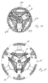
- Figs. 4 showing the folded state of the expander
- Fig. 5 showing the expanded state of said expander.
- the same synchronizing mechanisms are shown on a larger scale in Figs. 8 and 9, respectively.
- the synchronizing mechanism shown in Figs. 4, 5, and 8, 9 is as shown arranged at the sectional line B-B where the first module begins.
- a second corresponding synchronizing mechanism is arranged at the location where the last module ends in such a manner that the two synchronizing mechanisms are symmetrically arranged around the transverse centre of the expander.
- Each synchronizing mechanism comprises a synchronizing disk 12 arranged coaxially with the central longitudinal axis of the expander.
- the synchronizing disk 12 is pivotally connected to each of the expander segments 10 or to a disk segment 13 secured thereto by means of respective synchronizing arms 14.
- the illustrated embodiment includes thus six synchronizing arms 14.
- One end of each synchronizing arm 14 is pivotally journalled on the synchronizing disk 12 at bearings 15 arranged at the same mutual angular distance, here 60° and at the same distance from the centre of the disk.
- the other end of the synchronizing arms 14 is pivotally journalled in bearings 16 in the respective disk segment 13 on each of the expander segments.
- the synchronizing arms 14 are arranged alternately on one side and the opposite side of the synchronizing disk 12. It appears from Figs. 5 and 9, that when the expander expands the synchronizing disk 12 turns counter-clockwise, cf. Figs. 4, 5, 8, and 9.
- the expander 1 comprises at least one additional synchronizing mechanism of a completely identical structure.
- the synchronizing mechanisms are interconnected by means of a shaft 17 extending in the central longitudinal axis of the expander through a central opening in each of the synchronizing disks 12 and being secured thereto by means of keyway connections 18.
- the synchronizing disks 12 interconnected by means of the shaft 17 are forced to turn the same number of degrees counterclockwise during the expansion of the expander. Therefore the expander segments are expanded to the same extent opposite each of the two synchronizing mechanisms, and consequently the expander maintains its circular-cylindrical shape during the entire expansion irrespective of whether it faces more resistance at some areas than at other areas.
- a flexible plate 19 with overlapping edges 20 and 21 is arranged around the expander 1.
- This plate extends in the entire longitudinal direction of the expander and covers thus both the expander segments 10 and the spaces 11 resulting between said expander segments 10 when the expander 1 expands.
- the plate 19 is preferably a stainless rolled plate, but it can, of course, also be a plate of any other material, such as plastics.
- Locking means 22 and 23, respectively, are provided adjacent each of the overlapping edges 20, 21 of the plate, cf. Figs. 12 and 13. The locking means 22 and 23 are adapted to automatically enter a locking engagement when the desired straightening of the pipeline has been completed.
- the two locking means 22 and 23 arranged on their respective sides of the pate 19 meet and position themselves atop one another as shown in Figs. 13 and more clearly in Fig. 14.
- the locking means 22, 23 can for instance as it is known be grooves and projections, respectively, in the surface of the plate 19, but it is according to the invention preferred that said locking means are provided in form of a strong dual lock traded under the Trade Mark Dual Lock.
- locking means 22, 23 of this type are highly suitable for maintaining the plate 19 in the expanded state after the expander has been caused to contract so that it can be removed from the location in question inside the pipeline.
- the plate 19 forms a plate cylinder supporting the damaged, but straightened pipeline when the expander 1 contracts and is removed. Long pipelines can be straightened by repeating the process, and the inserted plate cylinders 19 can be used for the final repair or as preparation for a local repair prior to the insertion of a new plastic lining into a pipeline.
Description
Claims (6)
- A hydraulically actuatable expander for straightening and repairing partially collapsed pipelines by way of an insertion therein, characterised in that it comprises:at least one elongated cylinder housing with a central longitudinal axis and a plurality of cylinder bores or cylinder sleeves in a single section transverse to said longitudinal axis,a piston inserted in each cylinder bore or each cylinder sleeve, whereby the piston surface of said piston facing away from the longitudinal axis is secured on an expander segment partially surrounding the cylinder housing, and where the piston surface facing the longitudinal axis communicates with a hydraulic channel for the supply of hydraulic pressure for the expansion of the pistons and consequently of the expander segments secured thereto, said expander segments together surrounding the cylinder housing,at least two synchronizing mechanisms arranged at regular intervals in the longitudinal direction of the cylinder housing and being connected to the expander segments in such a manner that all said expander segments expand synchronously to the same extent, where said two synchronizing mechanisms furthermore are interconnected such that the expander segments also expand to the same extent at the position of one and at the position of the second synchronizing mechanism,and a flexible plate with overlapping edges arranged around the expander segments in such a manner that it continuously covers the expander segments and the spaces therebetween during the expansion,as well as locking means adjacent each of the overlapping edges of the plate, said locking means automatically entering a locking engagement when the desired straightening of the pipeline has been obtained.
- Expander as claimed in claim 1, characterised in that it comprises several cylinder bores or cylinder sleeves in a common section of the cylinder housing, said cylinder bores or said cylinder sleeves being arranged at a regular angular distance.
- Expander as claimed in claim 1 or 2, characterised in that the cylinder housing comprises several sections succeeding one another in the longitudinal direction of said cylinder housing, said sections forming a module.
- Expander as claimed in claim 3, characterised in that the cylinder housing is made of several interconnected modules.
- Expander as claimed in claims 2 to 4, characterised in that it comprises four modules, each modules comprising two sections with three cylinder sleeves provided with their respective pistons.
- Expander as claimed in claims 1 to 5, characterised in that it comprises two synchronizing mechanisms, each synchronizing mechanism being provided with a synchronizing disk pivotally connected to each expander segment by means of a plurality of synchronizing arms, where one end of said synchronizing arms is pivotally connected to the synchronizing disk and the opposite end is pivotally connected to their respective expander segments, whereby the synchronizing disks of said two synchronizing mechanisms are permanently interconnected by means of a shaft extending in the central longitudinal axis of the expander.
Applications Claiming Priority (3)
| Application Number | Priority Date | Filing Date | Title |
|---|---|---|---|
| DK103995 | 1995-09-19 | ||
| DK103995A DK103995A (en) | 1995-09-19 | 1995-09-19 | Hydraulically activatable expander |
| PCT/DK1996/000393 WO1997011306A1 (en) | 1995-09-19 | 1996-09-18 | Hydraulically actuatable expander |
Publications (2)
| Publication Number | Publication Date |
|---|---|
| EP0851987A1 EP0851987A1 (en) | 1998-07-08 |
| EP0851987B1 true EP0851987B1 (en) | 2002-02-06 |
Family
ID=8100314
Family Applications (1)
| Application Number | Title | Priority Date | Filing Date |
|---|---|---|---|
| EP96930034A Expired - Lifetime EP0851987B1 (en) | 1995-09-19 | 1996-09-18 | Hydraulically actuatable expander |
Country Status (5)
| Country | Link |
|---|---|
| EP (1) | EP0851987B1 (en) |
| AU (1) | AU6924096A (en) |
| DE (1) | DE69619118D1 (en) |
| DK (2) | DK103995A (en) |
| WO (1) | WO1997011306A1 (en) |
Families Citing this family (7)
| Publication number | Priority date | Publication date | Assignee | Title |
|---|---|---|---|---|
| US6240965B1 (en) * | 1998-04-24 | 2001-06-05 | Link-Pipe (H.K.), Ltd. | Apparatus for repair of high temperature and pressure conduits, method for repairing high temperature and pressure conduits, and a sealing device for repairing high temperature and pressure conduits |
| US7886831B2 (en) | 2003-01-22 | 2011-02-15 | Enventure Global Technology, L.L.C. | Apparatus for radially expanding and plastically deforming a tubular member |
| US7712522B2 (en) | 2003-09-05 | 2010-05-11 | Enventure Global Technology, Llc | Expansion cone and system |
| WO2006020960A2 (en) | 2004-08-13 | 2006-02-23 | Enventure Global Technology, Llc | Expandable tubular |
| US9175798B1 (en) * | 2014-06-05 | 2015-11-03 | Titan CMP Solutions LLC | Trenchless refurbishment of underground pipes |
| GB2579540B (en) | 2018-11-16 | 2022-10-05 | Turnbull Infrastructure & Utilities Ltd | Pipe repair |
| JP2023100247A (en) | 2022-01-05 | 2023-07-18 | イーアイティーアイ エス.アール.エル. | pipe repair device |
Family Cites Families (4)
| Publication number | Priority date | Publication date | Assignee | Title |
|---|---|---|---|---|
| GB2101262A (en) * | 1981-03-18 | 1983-01-12 | Lembit Maimets | Pipe sealing apparatus and jack |
| SE8702543D0 (en) * | 1987-06-17 | 1987-06-17 | Stig Westman | EQUIPMENT FOR WORK IN PIPELINES |
| GB2214260A (en) * | 1988-01-12 | 1989-08-31 | British Gas Plc | Mole |
| DE4410900A1 (en) * | 1993-12-02 | 1995-06-08 | Helmar Haas | Renovation element for sewers, drainage pipes, landfill pipes and the like the like |
-
1995
- 1995-09-19 DK DK103995A patent/DK103995A/en not_active Application Discontinuation
-
1996
- 1996-09-18 DK DK96930034T patent/DK0851987T3/en active
- 1996-09-18 EP EP96930034A patent/EP0851987B1/en not_active Expired - Lifetime
- 1996-09-18 AU AU69240/96A patent/AU6924096A/en not_active Abandoned
- 1996-09-18 DE DE69619118T patent/DE69619118D1/en not_active Expired - Lifetime
- 1996-09-18 WO PCT/DK1996/000393 patent/WO1997011306A1/en active IP Right Grant
Also Published As
| Publication number | Publication date |
|---|---|
| AU6924096A (en) | 1997-04-09 |
| DE69619118D1 (en) | 2002-03-21 |
| EP0851987A1 (en) | 1998-07-08 |
| WO1997011306A1 (en) | 1997-03-27 |
| DK103995A (en) | 1997-05-16 |
| DK0851987T3 (en) | 2002-05-27 |
Similar Documents
| Publication | Publication Date | Title |
|---|---|---|
| EP0851987B1 (en) | Hydraulically actuatable expander | |
| US4487052A (en) | Device and method for removing irregularities in or enlarging an underground duct | |
| EP3653919B1 (en) | Pipe repair method | |
| FI78148C (en) | ANORDING FROM THE FOLLOWING AV ETT UNDERJORDISKT ROER ELLER FOER AVLAEGSNANDE AV OREGELBUNDENHETER DAERI. | |
| DE2326844A1 (en) | PIPE BENDING MACHINE | |
| US4789268A (en) | Device and method for removing irregularities in or enlarging an underground duct | |
| DE19958103C1 (en) | Press tool for rotationally symmetrical hollow workpieces e.g. pipe fittings, has press surfaces displaced radially via 2 outer control bodies provided with angled control surfaces acting on inner control bodies | |
| US6240965B1 (en) | Apparatus for repair of high temperature and pressure conduits, method for repairing high temperature and pressure conduits, and a sealing device for repairing high temperature and pressure conduits | |
| US4657436A (en) | Device and method for removing irregularities in or enlarging an underground duct | |
| DE2439329A1 (en) | DEVICE FOR QUICKLY CHANGING THE LEVELING ROLLERS OF A ROLLER LEVELING MACHINE | |
| US3625046A (en) | Apparatus and method for straightening deformed rolls of sheet stock | |
| WO1990010511A1 (en) | Apparatus for forming a pipe from a sheet metal plate | |
| DE19924695C2 (en) | Expansion tool for hollow bodies and process for the production thereof | |
| DE4404712A1 (en) | Process for removing an earth core from a trenchless pipe and pig to carry out the process | |
| DE2934360A1 (en) | EXPANDABLE THORN FOR THE PRODUCTION OF TUBES | |
| EP0060715B1 (en) | Pipe sealing apparatus and jack | |
| US20020066300A1 (en) | Compact apparatus for grooving a tube and method for grooving a tube | |
| EP0017675B1 (en) | Expandable coiler mandrel | |
| DE3534662A1 (en) | Guided driving head of an apparatus for penetrating the soil | |
| DE3326350A1 (en) | EARTH DRILLING DEVICE AND DRILLING METHOD | |
| DE4318929C2 (en) | Press for the permanent connection of line pipe sections and elements such as fittings, fittings and molded parts | |
| DE10259111B3 (en) | Longitudinal slitting device for pipeline has carrier body with at least two longitudinally offset cutting roller pairs | |
| GB2224099A (en) | Alignment of shaft flanges | |
| JPS63172007A (en) | Turnbuckle and manufacture thereof | |
| DE2138933A1 (en) | Tire manufacturing device |
Legal Events
| Date | Code | Title | Description |
|---|---|---|---|
| PUAI | Public reference made under article 153(3) epc to a published international application that has entered the european phase |
Free format text: ORIGINAL CODE: 0009012 |
|
| 17P | Request for examination filed |
Effective date: 19980317 |
|
| AK | Designated contracting states |
Kind code of ref document: A1 Designated state(s): CH DE DK FR GB IT LI |
|
| 17Q | First examination report despatched |
Effective date: 19990714 |
|
| GRAG | Despatch of communication of intention to grant |
Free format text: ORIGINAL CODE: EPIDOS AGRA |
|
| GRAG | Despatch of communication of intention to grant |
Free format text: ORIGINAL CODE: EPIDOS AGRA |
|
| GRAH | Despatch of communication of intention to grant a patent |
Free format text: ORIGINAL CODE: EPIDOS IGRA |
|
| GRAH | Despatch of communication of intention to grant a patent |
Free format text: ORIGINAL CODE: EPIDOS IGRA |
|
| GRAA | (expected) grant |
Free format text: ORIGINAL CODE: 0009210 |
|
| REG | Reference to a national code |
Ref country code: GB Ref legal event code: IF02 |
|
| AK | Designated contracting states |
Kind code of ref document: B1 Designated state(s): CH DE DK FR GB IT LI |
|
| PG25 | Lapsed in a contracting state [announced via postgrant information from national office to epo] |
Ref country code: LI Free format text: LAPSE BECAUSE OF FAILURE TO SUBMIT A TRANSLATION OF THE DESCRIPTION OR TO PAY THE FEE WITHIN THE PRESCRIBED TIME-LIMIT Effective date: 20020206 Ref country code: IT Free format text: LAPSE BECAUSE OF FAILURE TO SUBMIT A TRANSLATION OF THE DESCRIPTION OR TO PAY THE FEE WITHIN THE PRESCRIBED TIME-LIMIT;WARNING: LAPSES OF ITALIAN PATENTS WITH EFFECTIVE DATE BEFORE 2007 MAY HAVE OCCURRED AT ANY TIME BEFORE 2007. THE CORRECT EFFECTIVE DATE MAY BE DIFFERENT FROM THE ONE RECORDED. Effective date: 20020206 Ref country code: CH Free format text: LAPSE BECAUSE OF FAILURE TO SUBMIT A TRANSLATION OF THE DESCRIPTION OR TO PAY THE FEE WITHIN THE PRESCRIBED TIME-LIMIT Effective date: 20020206 |
|
| REG | Reference to a national code |
Ref country code: CH Ref legal event code: EP |
|
| REF | Corresponds to: |
Ref document number: 69619118 Country of ref document: DE Date of ref document: 20020321 |
|
| PG25 | Lapsed in a contracting state [announced via postgrant information from national office to epo] |
Ref country code: DE Free format text: LAPSE BECAUSE OF FAILURE TO SUBMIT A TRANSLATION OF THE DESCRIPTION OR TO PAY THE FEE WITHIN THE PRESCRIBED TIME-LIMIT Effective date: 20020507 |
|
| ET | Fr: translation filed | ||
| REG | Reference to a national code |
Ref country code: DK Ref legal event code: T3 |
|
| REG | Reference to a national code |
Ref country code: CH Ref legal event code: PL |
|
| PG25 | Lapsed in a contracting state [announced via postgrant information from national office to epo] |
Ref country code: GB Free format text: LAPSE BECAUSE OF NON-PAYMENT OF DUE FEES Effective date: 20020918 |
|
| PLBE | No opposition filed within time limit |
Free format text: ORIGINAL CODE: 0009261 |
|
| STAA | Information on the status of an ep patent application or granted ep patent |
Free format text: STATUS: NO OPPOSITION FILED WITHIN TIME LIMIT |
|
| 26N | No opposition filed |
Effective date: 20021107 |
|
| GBPC | Gb: european patent ceased through non-payment of renewal fee |
Effective date: 20020918 |
|
| PG25 | Lapsed in a contracting state [announced via postgrant information from national office to epo] |
Ref country code: FR Free format text: LAPSE BECAUSE OF NON-PAYMENT OF DUE FEES Effective date: 20030603 |
|
| REG | Reference to a national code |
Ref country code: FR Ref legal event code: ST |
|
| PGFP | Annual fee paid to national office [announced via postgrant information from national office to epo] |
Ref country code: DK Payment date: 20060927 Year of fee payment: 11 |
|
| REG | Reference to a national code |
Ref country code: DK Ref legal event code: EBP |
|
| PG25 | Lapsed in a contracting state [announced via postgrant information from national office to epo] |
Ref country code: DK Free format text: LAPSE BECAUSE OF NON-PAYMENT OF DUE FEES Effective date: 20071001 |