US3625046A - Apparatus and method for straightening deformed rolls of sheet stock - Google Patents
Apparatus and method for straightening deformed rolls of sheet stock Download PDFInfo
- Publication number
- US3625046A US3625046A US872093A US3625046DA US3625046A US 3625046 A US3625046 A US 3625046A US 872093 A US872093 A US 872093A US 3625046D A US3625046D A US 3625046DA US 3625046 A US3625046 A US 3625046A
- Authority
- US
- United States
- Prior art keywords
- shoes
- core
- ram
- axis
- deformed
- Prior art date
- Legal status (The legal status is an assumption and is not a legal conclusion. Google has not performed a legal analysis and makes no representation as to the accuracy of the status listed.)
- Expired - Lifetime
Links
- 238000000034 method Methods 0.000 title description 39
- 238000005096 rolling process Methods 0.000 abstract description 5
- 230000000994 depressogenic effect Effects 0.000 description 21
- 239000000123 paper Substances 0.000 description 11
- 238000006243 chemical reaction Methods 0.000 description 4
- 238000007373 indentation Methods 0.000 description 4
- 239000012530 fluid Substances 0.000 description 3
- 239000002184 metal Substances 0.000 description 3
- 230000004323 axial length Effects 0.000 description 2
- 238000003780 insertion Methods 0.000 description 2
- 230000002093 peripheral effect Effects 0.000 description 2
- 230000015572 biosynthetic process Effects 0.000 description 1
- 230000037431 insertion Effects 0.000 description 1
- 230000001788 irregular Effects 0.000 description 1
- 238000012423 maintenance Methods 0.000 description 1
- 239000000463 material Substances 0.000 description 1
- 238000003466 welding Methods 0.000 description 1
Images


Classifications
-
- B—PERFORMING OPERATIONS; TRANSPORTING
- B65—CONVEYING; PACKING; STORING; HANDLING THIN OR FILAMENTARY MATERIAL
- B65H—HANDLING THIN OR FILAMENTARY MATERIAL, e.g. SHEETS, WEBS, CABLES
- B65H75/00—Storing webs, tapes, or filamentary material, e.g. on reels
- B65H75/005—Working on damaged packages, e.g. reshaping collapsed cores
-
- B—PERFORMING OPERATIONS; TRANSPORTING
- B21—MECHANICAL METAL-WORKING WITHOUT ESSENTIALLY REMOVING MATERIAL; PUNCHING METAL
- B21D—WORKING OR PROCESSING OF SHEET METAL OR METAL TUBES, RODS OR PROFILES WITHOUT ESSENTIALLY REMOVING MATERIAL; PUNCHING METAL
- B21D1/00—Straightening, restoring form or removing local distortions of sheet metal or specific articles made therefrom; Stretching sheet metal combined with rolling
- B21D1/06—Removing local distortions
- B21D1/08—Removing local distortions of hollow bodies made from sheet metal
-
- Y—GENERAL TAGGING OF NEW TECHNOLOGICAL DEVELOPMENTS; GENERAL TAGGING OF CROSS-SECTIONAL TECHNOLOGIES SPANNING OVER SEVERAL SECTIONS OF THE IPC; TECHNICAL SUBJECTS COVERED BY FORMER USPC CROSS-REFERENCE ART COLLECTIONS [XRACs] AND DIGESTS
- Y10—TECHNICAL SUBJECTS COVERED BY FORMER USPC
- Y10S—TECHNICAL SUBJECTS COVERED BY FORMER USPC CROSS-REFERENCE ART COLLECTIONS [XRACs] AND DIGESTS
- Y10S72/00—Metal deforming
- Y10S72/705—Vehicle body or frame straightener
Definitions
- a hydraulic ram is provided extending on an axis between the shoes and having a cylinder and an extensible piston rod which terminates in a pin coaxial with the axis and having a rounded distal end.
- One of the shoes has a raised, partcylindrical portion thereon having rolling engagement with the end of the cylinder remote from the piston rod, and the other shoe has an opening therein which removably receives the rounded distal end of the piston rod thereby providing for pivotal motion of both shoes with respect to the axis, whereby the shoes generally conform to an out-of-round configuration of the core without exerting side loading on the ram when the piston rod thereof is extended.
- This invention generally relates to an apparatus and method for straightening deformed rolls of sheet stock.
- the scrap value of a deformed roll of paper is a small fraction of the original cost of the paper and thus, a substantial loss is incurred unless the paper can be salvaged.
- the web of paper on the roll can, ,of course, be salvaged by rewinding the paper from the deformed roll onto a new, cylindrical core.
- this is a timeconsuming operation requiring rewinding apparatus which is not commonly available in printing and conversion plants.
- Pat. No. 3,292,903, granted Dec. 20, 1966 discloses apparatus for straightening deformed paper rolls which comprises a pair of shoes inserted in an end of a deformed core and, a ram-actuated mechanism for separating the shoes which is located exteriorly of the core.
- a pair of spaced-apart, outwardly curved shoes are provided for respectively engaging generally opposite internal surface areas of the core of a deformed roll, and a hydraulic ram is provided extending on an axis between the shoes and having first and second parts which are relatively movable in the direction of the axis, the parts respectively engaging the shoes.
- Each of the shoes has means thereon for permittiing pivotal motion thereof with respect to the axis of the ram so that the shoes may generally self-adjust and conform to an out-of-round configuration of the core without exerting side loading on the ram as the same is extended.
- an apparatus which comprises a pair of spacedapart, outwardly curved shoes, and a hydraulic ram which extends on an axis between the the shoes and which has first and second parts relatively movable in the direction of the axis, the shoes respectively having means permitting pivotal motion thereof with respect to the axis.
- Hydraulic pressure is applied to the ram thereby to extend the same so that the shoes respectively engage two generally opposite internal surface areas of the core and force the same relatively outwardly.
- the ram is then retracted and the apparatus rotated in the core to a different position. Hydraulic pressure is then again applied to the ram to extend the same so that the shoes now respectively engage another two generally opposite internal surface areas of the core and force the same relatively outwardly.
- Another object of the invention is to provide improved apparatus for straightening deformed rolls of sheet stock wherein the apparatus may be inserted into the interior regions of a deformed core.
- a further object of the invention is to provide improved apparatus of the type employing a hydraulic ram for straightening deformed rolls of sheet stock wherein side loading of the ram is substantially eliminated.
- Yet another object of the invention is to provide an improved method for straightening deformed rolls of sheet stock.
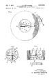
- FIG. 1 is a side view, partly in cross section, illustrating the apparatus of the invention
- FIG. 2 is a top view of two devices in accordance with the invention disposed in back-to-back relationship, with the top shoes removed;
- FIG. 3 is a side view showing an initial step in a first embodiment of the method of the invention.
- FIG. 4 is a side view showing another step in the first embodiment of the method of the invention.
- FIG. 5 is a side view showing a further step in the first embodiment of the method of the invention.
- FIG. 6 is a side view showing the final step in the first embodiment of the method of the invention.
- FIG. 7 is a fragmentary cross-sectional view further illustrating the method step of FIG. 6;
- FIG. 8 is a side view showing a modified form of the bottom shoe of the apparatus of the invention in which the part-cylindrical portion is rotated by 90 from the position of the embodiment of FIG. 1;
- FIG. 9 is a cross-sectional view taken along the line 99 of FIG. 8;
- FIG. 10 is a side view showing an initial step in a second embodiment of the method of the invention.
- FIG. 11 is a side view showing another step in the second embodiment of the method of the invention.
- FIG. 12 is a side view showing yet another step in the second embodiment of the method of the invention.
- FIG. 13 is a side view showing a further step in the second embodiment of the method of the inenvtion
- FIG. 14 is a side view showing the final step in the second embodiment of the method of the invention.
- FIG. 15 shows the cylindrical core resulting from the method of FIGS. 10 through 14;
- FIG. 16 is a longitudinal cross-sectional view showing the initial step in a third embodiment of the invention.
- FIG. 17 is a longitudinal cross-sectional view showing a further step in the third embodiment of the method of the invention employing the apparatus of the invention with a bottom shoe of the type shown in FIGS. 8 and 9.
- the apparatus of the invention generally indicated at 10 comprises top and bottom curved, metal shoes 12 and 14. As illustrated, shoes 12, 14 respectively have arcuate outer surfaces 16 and 18 which generally conform to the desired curvature of the core of a roll to be straightened.
- a hydraulic ram 20 is provided having a cylinder 22 with an open end 24 and a fiat, closed end 26. Piston rod 28 is positioned in cylinder 22 extending outwardly from open end 24.
- An elongated pin 30 is provided having a proximal end 32 removably secured to the outer end 34 of piston rod 28, as by a threaded stud shown in dashed lines at 33, and having a rounded or crowned distal end 36. It will be observed that the cylinder 22, piston rod 28 and pin 30 are disposed on an axis 38 which extends between shoes 12, 14.
- Bottom shoe 14 has a raised, part-cylindrical portion 40 secured to its inner surface 42 intermediate its ends in any suitable fashion, as by welding at 44. It will be seen that portion 40 extends transversely across the width dimension of bottom shoe 14. Part-cylindrical portion 40 is disposed in rolling engagement with flat end 26 of cylinder 22 thereby to permit pivotal or rocking motion of bottom shoe 14 with respect to axis 38.
- Top shoe 12 has a radiused socket 46 formed in its inner surface 48 intermediate its ends which removably receives rounded distal end 38 of pin 30, thus permitting pivotal movement of top shoe 12 with respect to axis 38.
- the shoes may generally conform to an out-of-round configuration of a deformed roll core without exerting side loading on the ram as the ram is extended by the application of hydraulic pressure to fluid inlet 50, which communicates with cylinder 22 in conventional fashion.
- Another radiused socket, shown in dashed lines at 52 may be formed in the inner surface 48 of the top shoe 12 offset from the center socket 46 in order to permit the expansive force to be exerted at a more advantageous location, depending upon the configuration of the deformed core, as shown in FIG. 17.
- FIG. 2 two apparatuses of the type shown in FIG. 1, identified as 10a and 10b are shown disposed in back-to-back abutting relationship.
- bottom shoes 14a, 14b are relatively elongated and have planar, opposite longitudinal sides 54' 56 which permit the shoes to be disposed in coplanar, abutting relationship, the diameters of the cylinders 22a, 22b being slightly less than the width of the shoes.
- the top shoes 12 (not shown in FIG. 2) preferably have the same configuration as the bottom shoes 14 so that they, likewise, may be disposed in coplanar abutting relationship.
- a typical deformed roll core 58 is shown, it being understood that a roll of sheet stock, such as paper (not shown) is supported on core 58 and is likewise deformed.
- Deformed core 58 which may be formed of relatively thin-walled cardboard or metal, is shown as having a typical depression 60 formed therein as a result of deformation of the roll supported thereon, as -by dropping or impingement upon some obstacle.
- apparatus 10 is positioned in the interior of the deformed core 58, as shown, and hydraulic pressure is applied to inlet 50 of cylinder 22 thereby to extend piston rod 28 and pin 30 so that shoes 12, 14 respectively engage generally opposite internal surface areas 62 and 64 of the deformed core 58, areas 62 and '64 being respectively on opposite sides of the depressed portion 60. It will immediately be observed that by virtue of the pivotal engagement of shoes 12 and 14 with pin 30 and partcylindrical portion 44, respectively, shoes 12, 14 conform to the configuration of the internal surface areas 62, 64 without applying side loading to the ram.
- ram 20 is retracted and rotated to the position shown in FIG. 4.
- a relatively short top shoe 66 may be substituted for the longer shoe 12 initially employed, shoe 66 however, also having the tapered socket- 46 formed in its inner surface which receives rounded distal end 36 of piston rod 30.
- Hydraulic pressure is then again applied to extend piston rod 28 and pin 30 until shoe 66 engages the reduced, depressed area 60a. and the bottom shoe 14 engages the opposite internal surface area 68.
- Application of hydraulic pressure is then continued to force areas 60a, 68 relatively outwardly so as to form core 58 into a generally ovoidal form, as shown in dashed lines at 58a, with the shorter shoe 66 forming the smaller end 60b.
- core 58 is shown in a configuration intermediate that shown in solid lines and that shown in dashed lines in FIG. 4, Le. during extension of ram 20 from its retracted to its extended position, and roll 70 of sheet stock, such as paper, is shown on the core 58. It will be understood that roll 70, in its initial deformed condition, had a depressed portion aligned with and causing formation of depressed portion 60 of core 58. As the opposite areas 600, 68 of core 58 are forced outwardly toward the ovoidal configuration shown in dashed lines at 58a in FIG.
- the depressed portion of roll 70 is likewise forced outwardly however, creases or indentations 72 tend to remain generally radially aligned with the boundries of depressed portion 60 of roll 58, a roll having such indentations being commonly referred to as a starred roll.
- Such creases or indentations may be removed by striking the outer peripheral surface 74 of roll 70 in the area of indentation 72 with a bat or pompom 76 with a motion shown by the arrows 78, 80 such striking being performed simultaneously with extension of ram 20 to form the core and roll into the ovoidal configuration shown in FIG. 4.
- ram 20a is retracted suificiently so as to substitute a longer top shoe 12a for the shorter top shoe 66.
- a second ram 20b is then positioned interiorly of core 58 with the axes of rams 20a, 20b being generally perpendicular, as shown.
- Fluid pressure is then selectively and/or simultaneously applied to rams 20a, 20b, which may be disposed in back-to-back relationship as shown in FIG. 7, so that the respective pairs of shoes 12a, 14a. and 12b, 14b form the core 58 into the desired generally cylindrical configuration.
- Rams 20a, 20b are then removed and conventional cylindrical plugs 82 are inserted in the open'ends 84 of the straightened core 58.
- Final touches may be given to the roll after it has been so plugged by rolling it over a fiat surface and striking high or uneven points on its outer periphery 74 with the pompom 76.
- cylinder 22 had an overall axial length of 4 /2 inches and an outside diameter of 2% inches, and piston rod 28 had an outside diameter of 1% inches and a maximum axial extension of 2 /2 inches.
- Pins 30 had an outside diameter of'1 A inches and varied in axial length from 1 inch to 7 inches.
- bottom shoe 114 a modified form of bottom shoe 114 is shown in which the raised, partcylindrical portion 140 is rotated by 90 from the position of the portion 140 shown in the embodiment of FIG. 1, portion 140 in this embodiment extending parallel with the length dimension of bottom shoe 114.
- the bottom shoe 114 may be employed in conjunction with the cylinder 22 and top shoe 12 of FIG. 1 in applications where the top and bottom shoes cannot be in alignment, such as that shown in FIG. 17.
- FIG. another typical deformed roll core 86 is shown having a typical deep depression 88 formed therein. It is desirable in straightening the deformed core 86 to apply the initial and intermediate expanding force at points on the interior surface of the core 86 which would be diametrically opposite if the core were cylindrical, i.e. at points spaced apart by a distance equal to one-half the circumference of the core when in its cylindrical form but following the deformed periphery of the core, as shown by the lines 90 in FIG. '10.
- top and bottom shoes 12, 14 are preferably positioned as closely as possible to such points 90.
- cylinder 22 is actuated thereby to extend piston rod 28 and pin 30 in the direction shown by the arrow 92, thereby forcing opposite portions 94, 96 of core 86 outwardly so as to reduce the depressed portion 88 outwardly, as shown by the arrow 98.
- piston rod 28 will reach its fully extended position so that no further outward expansion of core 86 would be possible.
- portions 94, 96 of core 86 have been expanded outwardly to the extent possible with the length of the particular pin 30 employed in the steps shown in FIGS. 10 and 11, cylinder 22 is actuated to retract piston rod 28 and a longer pin 30-1 is substituted for the shorter pin 30.
- Distal end 36 of the longer pin 30-1 is again seated in the central socket 46, and cylinder 22 is again actuated to extend piston rod 28 and pin 30-1 in direction 92 thereby further to expand por tions 94, 96 of core 86 outwardly, and further to reduce depressed portion 88 in direction 98.
- a second ram 20b (the ram and its components employed in the previous steps being identified with the suffix a) is introduced disposed at 90 with respect to ram 20a with its top and bottom shoes 12b, 14b respectively engaging the opposite portions 102, 100 of core 86, a relatively short pin 30b being employed with ram 20b.
- cylinder 22b is actuated to extend piston rod 28b and pin 30b in direction 104
- cylinder 22a of ram 20a is simultaneously actuated to retract piston rod 28a and pin 30-2 in direction 106, thereby causing the core 86 to begin to assume its desired cylindrical configuration.
- the extension of cylinder 28b and pin 30b together with the simultaneous retraction of piston rod 28a and pin 30a then continues until the core 86 has been restored to its cylindrical configuration, as shown in FIG. 15.
- a paper roll 108 is shown having a core 110 which is sufficiently collapsed to prevent initial insertion of the apparatus of the invention.
- core expanding apparatus 112 is provided having a pair of elongated, pointed, expansible elements 116, 118. Elements 116, 118, in their collapsed position, are inserted or driven into end 120 of the collapsed core 110, as shown. Elements 116, 118 are adapted for outward separating movement, in the direction shown by the arrows 122, by a suitable fluid power cylinder (not shown). Expanding apparatus 112 may be of the type illustrated and described in the aforesaid Pat. No. 3,292,903, or other similar apparatus for end-insertion into a collapsed core, as is well known to those skilled in the art.
- expanding apparatus 112 is then actuated to separate elements 116, 118 so as to Widen end opening 120 of core 110 sufficiently to introduce ram 20 therein.
- the opposite wall portions of the core become inclined inwardly away from opening 120 toward the opposite end 126 of the core, as shown in FIG. 17.
- a bottom shoe 114 of the type shown in FIGS. 8 and 9 and described above is employed with its part-cylindrical portion 140 thus being disposed at right angles to the longitudinal axis of core 110. This permits top and bottom shoes 112, 114 to accommodate themselves to the inclined relationship of the opposite walls of core 110, as shown.
- cylinder 22 With ram 20 thus positioned in the widened opening 120 of the collapsed core 110, cylinder 22 is actuated thereby to extend piston rod 28 and pin 30 in the direction shown by the arrow 124 thereby further to widen the opening 120. Ram 20 may then be moved toward the smaller end 126 of core 110 and the operation repeated until the collapsed core 110 has been expanded in at least one dimension sufficiently to perform the method steps of the type described above for restoring the core to its original cylindrical configuration.
- FIGS. 3-5 and 10-13 While employment of a single ram 20 has been shown in FIGS. 3-5 and 10-13, and two back-to-back rams 20a, 20b, in FIGS. 6 and 7, and 14 and 15 it will be readily understood that in the case of an elongated roll having an elongated deformed core, a number of rams may be employed at spaced intervals along the interior of the core, each ram being positioned in accordance with the location and configuration of the depressed portion 60 at that particular point, thus providing flexibility in straightening which is not afforded by the prior art devices abovedescribed.
- Apparatus for straightening deformed rolls of sheet stock comprising a pair of spaced-apart, outwardly curved shoes for respectively engaging generally opposite internal surface areas of the core of a deformed roll, and a hydraulic ram extending on an axis between said shoes and having first and second parts relatively movable in the direction of said axis, said parts respectively removably engaging said shoes, each of said shoes having means thereon for permitting pivotal motion thereof with respect to the respective part whereby said shoes may generally conform to an out-of-round configuration of said core without exerting side loading on said ram as the same is extended.
- pivotal means on one of said shoes comprises a raised, part-cylindrical portion on said one shoe engaging one of said ram parts.
- one of said ram parts includes a pin coaxial with said axis and having a rounded distal end, the pivotal means on one of said shoes comprising a socket for selectively, removably, swivelly receiving said distal end of said pin.
- said ram includes a cylinder having open and closed ends, and a piston rod in said cylinder and extending outwardly from said open end, said piston rod having a pin removably secured thereto coaxial with said axis and having a rounded distal end, the' pivotal means on one of said shoes comprising a raised, curved portion engaging said closed end of said cylinder, the pivotal means on the other of said shoes comprising a socket formed therein for selectively, removably, swivelly receiving said distal end of said pin.
- the method of straightening deformed rolls of sheet stock comprising the steps of (a) inserting in the core of the deformed roll an apparatus comprising a pair of spaced-apart, outwardly curved shoes, and a hydraulic ram extending on an axis between said shoes and having first and second parts relatively movable in the direction of said axis, said shoes respectively having means permitting pivotal motion thereof with respect to said axis; (b) applying hydraulic pressure to said ram thereby .to extend the same so that said shoes respectively engage two generally opposite internal surface areas of said core and force the same relatively outwardly; (c) retracting said ram and rotating said apparatus in said core to a different position; and again (d) applying hydraulic pressure to said ram thereby to extend the same so that said shoes respectively engage another two generally opposite internal surface areas of said core and force the same relatively outwardly.
- the method of straightening deformed rolls of sheet stock comprising the steps of: (a) inserting in the core of the deformed roll an apparatus comprising a pair of spaced-apart, outwardly curved shoes, and a hydraulic ram extending on an axis between said shoes and having first and second parts relatively movable in the direction of said axis, said shoes respectively having means permitting pivotal motion thereof with respect to said axis; (b) applying hydraulic pressure to said ram thereby to extend the same so that said shoes respectively engage two generally opposite internal surface areas of said core and force the same relatively outwardly; said core initially having a substantially depressed portion extending into its interior, said two areas being respectively on opposite sides of said depressed portion whereby forcing of said first-named areas relatively outwardly causes reduction of said depressed portion.
- the method of straightening deformed rolls of sheet stock comprising the steps of: (a) inserting in the core of the deformed roll in apparatus comprising a pair of spaced-apart, outwardly curved shoes, and a hydraulic ram extending on an axis between said shoes and having first and second parts relatively movable in the direction of said axis, said shoes respectively having means permitting pivotal motion thereof with respect to said axis; (b) applying hydraulic pressure to said ram thereby to extend the same so that said shoes respectively engage two generally opposite internal surface areas of said core and force the same relatively outwardly; said ram including a cylinder, a piston rod, and a pin removably secured to said piston rod and having a distal end removably swivelly engaging one of said shoes, said step (b) including initially employing a first said pin having a first predetermined length, and thereafter substituting for said first pin a second pin longer than said first pin.
- step (e) includes substituting a relatively shorter shoe for one of said shoes initially employed, and orienting said apparatus so that said shorter shoe engages said reduced depressed portion upon extension of said ram during said step (d).
- step (d) includes extending said ram sufficiently so that said shoes form said core into a generally oval configuration.
- step (d) includes extending said ram sufficiently so that the other of said initial shoes and said shorter shoe form said core into a generally ovoidal configuration with said shorter shoe forming the smaller end thereof.
- the method of straightening deformed rolls of sheet stock comprising the steps of: (a) inserting in the core of the deformed roll an apparatus comprising a pair of spaced-apart, outwardly curved shoes, and a hydraulic ram extending on an axis between said shoes and having first and second parts relatively movable in the direction of the axis, said shoes respectively having means permitting pivotal motion thereof with respect to said axis; (b) applying hydraulic pressure to said ram thereby to extend the same so that said shoes respectively engage two generally opposite internal surface areas of said core and force the same relatively outwardly; (c) inserting in said core a second apparatus comprising a second pair of spaced-apart, outwardly curved shoes, and a second hydraulic ram extending on a second axis between said second shoes and having first and second parts relatively movable in the direction of said second axis, said second shoes respectively having means permitting pivotal motion with respect to said second axis, said second apparatus being positioned closely adjacent said first-named apparatus with their respective
- the method of straightening deformed rolls of sheet stock comprising the steps of: (a) inserting in the core of the deformed roll an apparatus comprising a pair of spaced-apart, outwardly curved shoes, and a hydraulic ram extending on an axis between said shoes and having first and second parts relatively movable in the direction of said axis, said shoes respectively having means permitting pivotal motion thereof with respect to said axis; (b) applying hydraulic pressure to said ram thereby to extend the same so that said shoes respectively engage two generally opposite internal surface areas of said core and force the same relatively outwardly, said shoes being elongated in the direction of their curvature and are of generally equal length, said step (b) including extending said ram sufficiently so that said core is elongated with the internal surface areas respectively intermediate said first-named surface areas defining spaced generally parallel planes.
- the method of claim 19 comprising the further steps of: (c) inserting in said core a second apparatus comprising a second pair of spaced-apart, outwardly curved shoes, and a second hydraulic ram extending on a second axis between said second shoes and having first and second parts relatively movable in the direction of said second axis, said second shoes respectively having means permitting pivotal motion with respect to said second axis, said second apparatus being positioned closely adjacent said first-named apparatus with their respective axes generally perpendicular; and (d) simultaneously applying hydraulic pressure to both of said rams whereby the respective shoes engage the respective internal surface areas of said core and force the same relatively outwardly into a generally cylindrical configuration; all of said shoes having curved outer surfaces generally conformng to the inner surface of an undeformed roll core.
- the method of straightening deformed rolls of sheet stock comprising the steps of (a) inserting an expansion tool in one end of the collapsed core of the deformed roll and expanding the same thereby to widen the opening of said core in said one end; (b) inserting through said widened opening at said one end of said core an apparatus comprising a pair of spaced-apart, outwardly curved shoes, and a hydraulic ram extend-ing on an axis between said shoes and having first and second parts relatively movable in the direction of said axis, said shoes respectively having means permitting pivotal motion thereof with respect to said axis; (c) applying hydraulic pressure to said ram thereby to extend the same so that said shoes respectively engage two generally opposite internal surface areas of said core and force the same relatively outwardly.
Abstract
Description
Applications Claiming Priority (1)
| Application Number | Priority Date | Filing Date | Title |
|---|---|---|---|
| US87209369A | 1969-10-29 | 1969-10-29 |
Publications (1)
| Publication Number | Publication Date |
|---|---|
| US3625046A true US3625046A (en) | 1971-12-07 |
Family
ID=25358818
Family Applications (1)
| Application Number | Title | Priority Date | Filing Date |
|---|---|---|---|
| US872093A Expired - Lifetime US3625046A (en) | 1969-10-29 | 1969-10-29 | Apparatus and method for straightening deformed rolls of sheet stock |
Country Status (8)
| Country | Link |
|---|---|
| US (1) | US3625046A (en) |
| CA (1) | CA932636A (en) |
| DE (1) | DE2053202C3 (en) |
| FI (1) | FI60655C (en) |
| FR (1) | FR2066740A5 (en) |
| GB (1) | GB1288654A (en) |
| NO (1) | NO135358C (en) |
| SE (1) | SE373340B (en) |
Cited By (13)
| Publication number | Priority date | Publication date | Assignee | Title |
|---|---|---|---|---|
| US3751008A (en) * | 1971-10-14 | 1973-08-07 | Natt N Mc | Apparatus for restoring damaged paper rolls |
| US3961516A (en) * | 1975-01-08 | 1976-06-08 | Priester Jack E | Apparatus and method for re-forming and maintaining the circular shape of a deformed roll of material |
| US4270379A (en) * | 1979-05-03 | 1981-06-02 | Brammall, Inc. | Roll straightening tool |
| DE3208974A1 (en) * | 1982-03-12 | 1983-09-22 | Drespa, Gerd, 4600 Dortmund | Set of straightening tools |
| US4584863A (en) * | 1985-06-06 | 1986-04-29 | Steck Manufacturing Company, Inc. | Automobile body repair tool |
| US4783053A (en) * | 1986-11-07 | 1988-11-08 | Mordechai Yirmiyahu | Device for force-opening doors |
| US4803881A (en) * | 1987-02-02 | 1989-02-14 | Dudley Winfred L | Pipe stretching apparatus |
| US4888975A (en) * | 1988-04-18 | 1989-12-26 | Soward Milton W | Resilient wedge for core expander tool |
| US5634361A (en) * | 1994-05-24 | 1997-06-03 | Advanced Machine Systems | Apparatus and method for straightening damaged or bent wheels |
| US20030159267A1 (en) * | 2001-03-16 | 2003-08-28 | Lafevers Mark | Continuous track drive unit handling, installation, and removal system and method |
| US20100294016A1 (en) * | 2009-05-21 | 2010-11-25 | Barr Fabrication | System and Method for Removal of Dents from Wind Turbine Masts |
| CN102764795A (en) * | 2012-04-09 | 2012-11-07 | 中国石油天然气集团公司 | Steel hot bend orifice roundness calibration system and its method |
| US20170175715A1 (en) * | 2015-12-21 | 2017-06-22 | General Electric Company | System and Method for Repairing Dents in Wind Turbine Tower Sections and a Related Dent Repair Tool |
Families Citing this family (1)
| Publication number | Priority date | Publication date | Assignee | Title |
|---|---|---|---|---|
| CN107570558B (en) * | 2017-09-21 | 2018-12-28 | 安徽天沃重工机械有限公司 | A kind of shaping machine for tank body of oil tank |
-
1969
- 1969-10-29 US US872093A patent/US3625046A/en not_active Expired - Lifetime
-
1970
- 1970-10-26 CA CA096569A patent/CA932636A/en not_active Expired
- 1970-10-26 SE SE7014439A patent/SE373340B/en unknown
- 1970-10-27 NO NO4076/70A patent/NO135358C/en unknown
- 1970-10-28 GB GB1288654D patent/GB1288654A/en not_active Expired
- 1970-10-28 FI FI2899/70A patent/FI60655C/en not_active IP Right Cessation
- 1970-10-29 DE DE2053202A patent/DE2053202C3/en not_active Expired
- 1970-10-29 FR FR7039108A patent/FR2066740A5/fr not_active Expired
Cited By (19)
| Publication number | Priority date | Publication date | Assignee | Title |
|---|---|---|---|---|
| US3751008A (en) * | 1971-10-14 | 1973-08-07 | Natt N Mc | Apparatus for restoring damaged paper rolls |
| US3961516A (en) * | 1975-01-08 | 1976-06-08 | Priester Jack E | Apparatus and method for re-forming and maintaining the circular shape of a deformed roll of material |
| US4270379A (en) * | 1979-05-03 | 1981-06-02 | Brammall, Inc. | Roll straightening tool |
| DE3208974A1 (en) * | 1982-03-12 | 1983-09-22 | Drespa, Gerd, 4600 Dortmund | Set of straightening tools |
| US4584863A (en) * | 1985-06-06 | 1986-04-29 | Steck Manufacturing Company, Inc. | Automobile body repair tool |
| US4783053A (en) * | 1986-11-07 | 1988-11-08 | Mordechai Yirmiyahu | Device for force-opening doors |
| US4803881A (en) * | 1987-02-02 | 1989-02-14 | Dudley Winfred L | Pipe stretching apparatus |
| US4888975A (en) * | 1988-04-18 | 1989-12-26 | Soward Milton W | Resilient wedge for core expander tool |
| US5634361A (en) * | 1994-05-24 | 1997-06-03 | Advanced Machine Systems | Apparatus and method for straightening damaged or bent wheels |
| US20030159267A1 (en) * | 2001-03-16 | 2003-08-28 | Lafevers Mark | Continuous track drive unit handling, installation, and removal system and method |
| US6654994B2 (en) * | 2001-03-16 | 2003-12-02 | Mark LaFevers | Continuous track drive unit handling, installation, and removal system and method |
| US6922881B2 (en) * | 2001-03-16 | 2005-08-02 | Lafevers Mark | Method for installing and removing a continuous track drive unit |
| US20100294016A1 (en) * | 2009-05-21 | 2010-11-25 | Barr Fabrication | System and Method for Removal of Dents from Wind Turbine Masts |
| US8245558B2 (en) * | 2009-05-21 | 2012-08-21 | Barr Fabrication | System and method for removal of dents from wind turbine masts |
| US8813534B2 (en) | 2009-05-21 | 2014-08-26 | Barr Fabrication | Method for removal of dents from wind turbine masts |
| CN102764795A (en) * | 2012-04-09 | 2012-11-07 | 中国石油天然气集团公司 | Steel hot bend orifice roundness calibration system and its method |
| CN102764795B (en) * | 2012-04-09 | 2014-11-05 | 中国石油天然气集团公司 | Steel hot bend orifice roundness calibration system and its method |
| US20170175715A1 (en) * | 2015-12-21 | 2017-06-22 | General Electric Company | System and Method for Repairing Dents in Wind Turbine Tower Sections and a Related Dent Repair Tool |
| US10288045B2 (en) * | 2015-12-21 | 2019-05-14 | General Electric Company | System and method for repairing dents in wind turbine tower sections and a related dent repair tool |
Also Published As
| Publication number | Publication date |
|---|---|
| NO135358C (en) | 1977-03-30 |
| DE2053202A1 (en) | 1971-05-13 |
| CA932636A (en) | 1973-08-28 |
| SE373340B (en) | 1975-02-03 |
| DE2053202C3 (en) | 1974-03-07 |
| GB1288654A (en) | 1972-09-13 |
| FI60655C (en) | 1982-03-10 |
| FI60655B (en) | 1981-11-30 |
| NO135358B (en) | 1976-12-20 |
| DE2053202B2 (en) | 1973-08-02 |
| FR2066740A5 (en) | 1971-08-06 |
Similar Documents
| Publication | Publication Date | Title |
|---|---|---|
| US3625046A (en) | Apparatus and method for straightening deformed rolls of sheet stock | |
| US1647447A (en) | Method of fastening tubular bodies in holes of other bodies | |
| US3595047A (en) | Method of forming o-ring grooves | |
| US3635440A (en) | Force-exerting apparatus | |
| US4262518A (en) | Tube expander and method | |
| US20060236737A1 (en) | Method and device for manufacturing UOE steel pipes | |
| JP4567336B2 (en) | Apparatus and method for expanding and forming can body | |
| US3749365A (en) | Primary opening apparatus | |
| US3907371A (en) | Drop center truck rim and method of forming same | |
| US3180130A (en) | Mandrel for preventing wrinkling of pipes during bending thereof | |
| US3677058A (en) | Apparatus and method for restoring deformed rolls of sheet stock to cylindrical shape | |
| WO1990010511A1 (en) | Apparatus for forming a pipe from a sheet metal plate | |
| US3566661A (en) | Metal forming | |
| US3815394A (en) | Machine and method for forming tubular adjustable elbows | |
| DE3224308C2 (en) | Method and apparatus for manufacturing corrugated multilayer metal bellows | |
| JPH07290170A (en) | Head for mechanical pipe expander | |
| US3357229A (en) | Apparatus for forming a beaded shell | |
| US4397173A (en) | Tube expander | |
| US2691906A (en) | Sizing pipe ends | |
| US4270379A (en) | Roll straightening tool | |
| US4027518A (en) | Hydraulic press | |
| US6865918B2 (en) | Tube compressing roller die | |
| US2164724A (en) | Rolling mill for enlarging hollow bodies | |
| US3344634A (en) | Sizing cylindrical sections | |
| US3260097A (en) | Apparatus for expanding tubular members |
Legal Events
| Date | Code | Title | Description |
|---|---|---|---|
| AS | Assignment |
Owner name: TYDEN-INDIANA INC.; 1100 WOHLERT ST., ANGOLA, IN. Free format text: ASSIGNMENT OF ASSIGNORS INTEREST.;ASSIGNOR:BRAMMALL, INC., A CORP. OF IN;REEL/FRAME:004118/0684 Effective date: 19830314 |
|
| AS | Assignment |
Owner name: BRAMMALL, INC., INDIANA Free format text: CHANGE OF NAME;ASSIGNOR:TYDEN-INDIANA, INC.;REEL/FRAME:004129/0069 Effective date: 19830307 Owner name: BRAMMALL, INC., Free format text: CHANGE OF NAME;ASSIGNOR:TYDEN-INDIANA, INC.;REEL/FRAME:004129/0069 Effective date: 19830307 |
|
| AS | Assignment |
Owner name: AMERICAN CAPITAL FINANCIAL SERVICES, INC., MARYLAN Free format text: ASSIGNMENT OF ASSIGNORS INTEREST;ASSIGNORS:BRAMMALL, INC.;TELESIS TECHNOLOGIES, INC.;TYDEN GROUP HOLDINGS;AND OTHERS;REEL/FRAME:016309/0609 Effective date: 20050502 |
|
| AS | Assignment |
Owner name: AMERICAN CAPITAL FINANCIAL SERVICES, INC., MARYLAN Free format text: CORRECTIVE ASSIGNMENT TO CORRECT THE CHANGE THE NATURE OF CONVEYANCE FROM ASSIGNMENT TO SECURITY AGREEMENT PREVIOUSLY RECORDED ON REEL 016309 FRAME 0609;ASSIGNORS:BRAMMALL, INC.;TELESIS TECHNOLOGIES, INC.;TYDEN GROUP HOLDINGS;AND OTHERS;REEL/FRAME:016891/0160 Effective date: 20050502 |
|
| AS | Assignment |
Owner name: WELLS FARGO BANK, NATIONAL ASSOCIATION, CALIFORNIA Free format text: SECURITY INTEREST;ASSIGNOR:E.J. BROOKS COMPANY;REEL/FRAME:034380/0804 Effective date: 20141121 |
|
| AS | Assignment |
Owner name: E.J. BROOKS COMPANY (AS SUCCESSOR BY MERGER TO BRA Free format text: RELEASE OF PATENT COLLATERAL;ASSIGNOR:WELLS FARGO BANK, NATIONAL ASSOCIATION, AS AGENT;REEL/FRAME:038079/0030 Effective date: 20160311 |