EP0851527A2 - Vehicle side window glass antenna for radio broadcast waves - Google Patents
Vehicle side window glass antenna for radio broadcast waves Download PDFInfo
- Publication number
- EP0851527A2 EP0851527A2 EP97122567A EP97122567A EP0851527A2 EP 0851527 A2 EP0851527 A2 EP 0851527A2 EP 97122567 A EP97122567 A EP 97122567A EP 97122567 A EP97122567 A EP 97122567A EP 0851527 A2 EP0851527 A2 EP 0851527A2
- Authority
- EP
- European Patent Office
- Prior art keywords
- horizontal
- vertical
- window glass
- glass
- strip
- Prior art date
- Legal status (The legal status is an assumption and is not a legal conclusion. Google has not performed a legal analysis and makes no representation as to the accuracy of the status listed.)
- Granted
Links
- 239000005357 flat glass Substances 0.000 title claims abstract description 83
- 239000011521 glass Substances 0.000 claims abstract description 76
- 230000035945 sensitivity Effects 0.000 description 9
- 238000012986 modification Methods 0.000 description 7
- 230000004048 modification Effects 0.000 description 7
- 230000002093 peripheral effect Effects 0.000 description 4
- 230000000052 comparative effect Effects 0.000 description 3
- 238000010586 diagram Methods 0.000 description 2
- 230000000694 effects Effects 0.000 description 2
- 238000005259 measurement Methods 0.000 description 2
- 239000005391 art glass Substances 0.000 description 1
- 238000005452 bending Methods 0.000 description 1
- 230000005540 biological transmission Effects 0.000 description 1
- 238000005485 electric heating Methods 0.000 description 1
- 238000002474 experimental method Methods 0.000 description 1
- WABPQHHGFIMREM-UHFFFAOYSA-N lead(0) Chemical compound [Pb] WABPQHHGFIMREM-UHFFFAOYSA-N 0.000 description 1
- 239000002184 metal Substances 0.000 description 1
- 238000000034 method Methods 0.000 description 1
- 238000007650 screen-printing Methods 0.000 description 1
Images


Classifications
-
- H—ELECTRICITY
- H01—ELECTRIC ELEMENTS
- H01Q—ANTENNAS, i.e. RADIO AERIALS
- H01Q1/00—Details of, or arrangements associated with, antennas
- H01Q1/12—Supports; Mounting means
- H01Q1/1271—Supports; Mounting means for mounting on windscreens
-
- H—ELECTRICITY
- H01—ELECTRIC ELEMENTS
- H01Q—ANTENNAS, i.e. RADIO AERIALS
- H01Q1/00—Details of, or arrangements associated with, antennas
- H01Q1/12—Supports; Mounting means
Definitions
- the present invention relates to a glass antenna attached to a vehicle side window glass such as for automobiles, particularly of the kind suited for receiving FM radio broadcast waves and AM radio broadcast waves.
- Examples of glass antennas having been heretofore known and put into practical use are an antenna attached to a marginal area or space of a rear window glass above or below a defogger electric heating element and an antenna including a conductive strip provided to a windshield, the former antenna however being not always capable of attaining a sufficient reception gain since the space occupied by the antenna is required to be small for eliminating the possibility that the antenna makes poor the visibility.
- the latter antenna i.e., the antenna provided to a windshield can attain a relatively high reception gain but is encountered by a larger restriction on its attaching place than the rear window glass so that it never blocks the driver's visibility.
- a novel and improved glass antenna attached to a vehicle side window glass for receiving radio waves, the window glass having a pair of vertically opposed upper and lower edges and a pair of horizontally opposed lateral edges, the glass antenna comprising a feed point disposed adjacent one of the lateral edges of the window glass, a first vertical element extending upwardly from the feed point along one of the lateral edges to a place adjacent the upper edge of the window glass, a first horizontal element extending from the first vertical element along the upper edge to a nearly central portion of the window glass, a second vertical element extending from the first horizontal element through the nearly central portion to a place adjacent the lower edge of the window glass, a second horizontal element extending from the second vertical element along the lower edge to a place adjacent the other of the lateral edges, and a third vertical element extending upwardly from the second horizontal element along the other of the lateral edges.
- the glass antenna further comprises a third horizontal element having a bent shape and consisting of a pair of horizontal conductive strips and a vertical conductive strip, the third horizontal element connecting between the first horizontal element and the second vertical element.
- all of the horizontal and vertical elements are constituted by a single conductive strip.
- At least part of the horizontal and vertical conductive strips constituted by a plurality of conductive strips.
- all of the horizontal and vertical conductive strips are constituted by a plurality of conductive strips, respectively.
- a glass antenna attached to a vehicle side window glass for receiving radio waves, the window glass having a pair of vertically opposed upper and lower edges and a pair of horizontally opposed lateral edges, the glass antenna comprising a feed point disposed at an upper corner of the window glass, a first horizontal element extending from the feed point along the upper edge to a nearly central portion of the window glass, a first vertical element extending from the first horizontal element through the nearly central portion to a place adjacent the lower edge of the window glass, a second horizontal element extending from the first vertical element along the lower edge to a place adjacent the other of the lateral edges, and a second vertical element extending from the second horizontal element along the other of the lateral edges.
- the glass antenna further comprises a third vertical element having a bent shape and consisting of a pair of vertical conductive strips and a horizontal conductive strip, the third vertical element connecting between the feed point and the first horizontal element.
- a glass antenna attached to a vehicle side window glass for receiving radio waves, the window glass having a pair of vertically opposed upper and lower edges and a pair of horizontally opposed lateral edges, the glass antenna comprising a feed point disposed adjacent one of the lateral edges of the window glass, a first vertical element extending downwardly from the feed point along the one lateral edge to a place adjacent the lower edge of the window glass, a first horizontal element extending from the first vertical element along the lower edge to a nearly central portion of the window glass between the lateral edges, a second vertical element extending upwardly from the first horizontal element through the nearly central portion to a place adjacent the upper edge of the window glass, a second horizontal element extending from the second vertical element along the upper edge to a place adjacent the other of the lateral edges, and a third vertical element extending downwardly from the second horizontal element along the other of the lateral edges.
- a glass antenna attached to vehicle side window glass for receiving radio waves the window glass having a pair of vertically opposed upper and lower edges and a pair of horizontally opposed lateral edges
- the glass antenna comprising a feed point disposed at a lower corner of the window glass, a first horizontal element extending from the feed point along the lower edge to a nearly central portion of the window glass, a first vertical element extending upwardly from the first horizontal element through the nearly central portion to a place adjacent the upper edge of the window glass, a second horizontal element extending from the first vertical element along the upper edge to a place adjacent the other of the lateral edges, and a second vertical element extending downwardly from the second horizontal element along the other of the lateral edges.
- first vertical element and the first horizontal element are disposed along the peripheral edges of the window glass
- second vertical element is disposed at nearly central portion of the window glass
- third vertical element is disposed along the peripheral edge of the window glass so that the antenna has an S-shaped pattern when observed on the window glass which is rotated 90 degrees.
- the element having a bent shape or ⁇ -shape may be provided adjacent the feed point or at an intermediate portion of the antenna as in the embodiments shown in Figs. 3 to 5 for increasing the total length of the antenna. In such a case, the first vertical element can be omitted.
- one vertical strip can be omitted so that the antenna includes only two vertical elements as in the embodiments shown in Figs. 6 and 8.
- the first vertical element, the third vertical element, the first horizontal element and the second horizontal element are disposed along the peripheral edges of the window glass in a way as to be at least 10 mm distant from the edges so that the reception gain is not lowered by the influence of the vehicle metal body.
- the antenna may have an S-shaped pattern which is entirely doubled as in the embodiment shown in Fig. 4 or partly doubled as in Fig. 2.
- the antenna of this invention having an S-shaped pattern when observed on the window glass which is rotated 90 degrees can have a larger length as compared with an E-shaped pattern consisting of three parallel strips disposed adjacent upper and lower edges and at a central portion therebetween and a vertical strip adjacent one lateral edge connecting the ends of the parallel strips or a pattern having a strip extending one time around the window glass, and thus can attain a higher reception gain for AM radio broadcast waves and FM radio broadcast waves. Further, by the effect of the vertical strip disposed at the central portion of the window glass, the antenna of this invention can have a larger effective receiving area as compared with the antenna of the pattern having a strip extending one time around the periphery of the window glass.
- the antenna of this invention having a partly or entirely doubled strip arrangement can further increase the effective receiving area, thus making it possible not only to improve the reception gain for the AM radio broadcast waves but to receive with good sensitivity long waves of 144 to 288 KHz band in Europe and short waves.
- the antenna of this invention can be provided with various additional elements consisting of a horizontal strip or vertical strip, or having an L-shape, T-shape, ⁇ -shape or the like made up of a combination of horizontal and vertical strips.
- the antenna of this invention may be additionally provided with an impedance matching circuit, pre-amplifier circuit or the like as an external circuit.
- the antenna of this invention can be provided to either of the left and right side windows and can receive only by itself and with good sensitivity AM radio broadcast waves and FM radio broadcast waves.
- the antenna of this invention can, of course, be used together with another glass antenna for reception of FM radio broadcast waves provided to the other side window (in this instance, it is desirable to use an antenna of the structure of this invention but an antenna of the structure other than this invention can be used), a glass antenna for FM radio broadcast waves provided to a rear window glass, an antenna provided to a windshield or a pole antenna to carry out diversity reception.
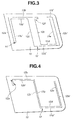
- Fig. 1 shows an automobile side window glass in which the present invention is embodied.
- a single piece of glass plate 10 is used as the window glass.
- a glass antenna 12 for receiving AM radio broadcast waves and FM radio broadcast waves according an embodiment of the present invention is installed on an inboard surface of the glass plate 10.
- the glass antenna 12 has an S-like pattern when observed on the glass plate 10 which is rotated 90 degrees so that the left-hand and right-hand lateral edges of the glass plate 10 oppose vertically.
- the glass antenna 12 includes a feed point 14, a first vertical strip 12a of the length of 320 mm extending upwardly from the feed point 14 along a right-hand lateral edge of the glass plate 10, a first horizontal strip 12b of the length of 330 mm extending along an upper edge of the glass plate 10 to a nearly widthwise central region of the glass plate 10 (i.e., the nearly central region of the glass plate 10 between the left-hand and the right-hand edges thereof), a second vertical strip 12c of the length of 370 mm extending downwardly along the nearly widthwise central region of the glass plate 10, a second horizontal strip 12d of the length of 330 mm extending along a lower edge of the glass plate 10 to the left-hand lateral edge of the glass plate 10 which is opposite to the first vertical strip 12a, a third vertical strip 12e of the length of 370 mm extending upwardly along the left-hand lateral edge of the glass plate 10, and a third horizontal strip 12f which is short, i.e., of the length of 100 mm
- the first vertical strip 12a, first horizontal strip 12b, second vertical strip 12c, second horizontal strip 12d, third vertical strip 12e and third horizontal strip 12f constitute a first vertical main antenna element, first horizontal main antenna element, second vertical main antenna element, second horizontal main antenna element, third vertical main antenna element and third horizontal main antenna element, respectively.
- the glass antenna 12 is formed by screen printing a conductive paste onto the glass surface and baking the printed paste simultaneously with the bending process of the glass plate 10.
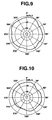
- the directional characteristics have little drop or fall of reception gain (i.e., dip) resulting due to the difference in the direction of transmission of a broadcast wave, and therefore it will be seen that the glass antenna 12 has quite good directional characteristics.
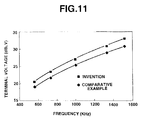
- another glass antenna 12' was provided to a window glass 10' on the other side of the automotive vehicle, and measurement of the receiving ability or sensitivity of the glass antenna 12' for AM radio broadcast waves of the frequency band from 530 to 1600 KHz was made.
- the measured sensitivity is depicted in terminal voltage in Fig. 11.
- an antenna consisting of a conductive strip which extends from a feed point at a corner of a glass plate of the same dimensions as the window glass 10
- a comparative example one time around the peripheral portion of the window glass
- Fig. 2 shows a modification of the glass antenna shown in Fig. 1.
- the first vertical strip 12a, the first horizontal strip 12b, the second vertical strip 12c and the second horizontal strip 12d have the same structure and dimensions as those of the embodiment shown in Fig. 1.
- an additional vertical strip 12e' (350 mm long) and additional horizontal strip 12f' (80 mm long) are respectively provided so that the third vertical main antenna element and the third horizontal main element are respectively made up of conductive strips which are provided double, i.e., are respectively constituted by a plurality of conductive strips.
- an auxiliary element 16 consisting of a vertical strip 16a of the length of 340 mm extending along the first vertical strip 12a and a horizontal strip 16b of the length of 400 mm extending along the first horizontal strip 12b.
- an auxiliary element 18 consisting of a vertical strip 18a of the length of 300 mm extending along the fast vertical strip 12a, a horizontal strip 18b of the length of 300 mm extending along the first horizontal strip 12b, and a vertical strip 18c of the length of 350 mm extending along the second vertical strip 12c.
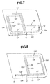
- Fig. 3 shows another modification of the glass antenna shown in Fig 1.
- the feed point 14 is disposed at the lower left-hand corner of the glass plate 10.
- the first vertical strip 12a of the length of 320 mm extends along the left-hand lateral edge of the glass plate 10.
- the first horizontal strip 12b is a little lengthened so as to be 380 mm long, whereas the second vertical strip 12c is a little shortened so as to be 350 mm long.
- the third horizontal strip 12f has a bent shape and connects between the first horizontal strip 12b and the second vertical strip 12c.
- the third horizontal strip 12f is made up of a pair of parallel horizontal parts of the length of 70 mm and a vertical part of the length of 20 mm.
- the second horizontal strip 12d is shortened so as to be 250 mm.
- the third vertical strip 12e is shortened so as to be 350 mm long.
- the antenna 12 further includes an additional first vertical strip 12a' of the length of 300 mm extending along the first vertical strip 12a, an additional first horizontal strip 12b' extending along the first horizontal strip 12b and located inside of same, an additional second vertical strip 12c' of the length of 350 mm extending along the second vertical strip 12c, an additional second horizontal strip 12d' of the length of 390 mm extending along the second horizontal strip 12d, an additional third vertical strip 12e' of the length of 370 mm extending along the third vertical strip 12e, and an additional third horizontal strip 12f' of the length of 80 mm located adjacent the upper free end of the third vertical strip 12e.
- the antenna 12 of this embodiment has a doubled pattern, i.e., the first vertical antenna element, first horizontal antenna element, second vertical antenna element, second horizontal antenna element and third vertical antenna element are respectively constituted by two conductive strips, i.e., by the first vertical strips 12a and 12a', first horizontal strips 12b and 12b', second vertical strips 12c and 12c', second horizontal strips 12d and 12d' and third vertical strips 12e and 12e'.
- Fig. 4 shows another modification of the antenna 12 shown in Fig. 1.
- the feed point 14 is disposed at the upper left-hand corner of the glass plate 10.
- the first vertical strip 12a is shortened and has a U-like bent shape so as to extend downwardly from the feed point 14 and is then bent upwardly to be connected to the first horizontal strip 12b.
- the antenna 12 further includes an additional first horizontal strip 12b' extending along the first horizontal strip 12b, an additional second vertical strip 12c' extending along the second vertical strip 12c, an additional second horizontal strip 12d' extending along the second horizontal strip 12d and an additional third vertical strip 12e' extending along the third vertical strip 12e.
- the conductive strips are partly arranged double.
- first horizontal antenna element, second vertical antenna element, second horizontal antenna element and third vertical antenna element are respectively constituted by two conductive strips, i.e., by the first horizontal strips 12b and 12b', the second vertical strips 12c and 12c', the second horizontal strips 12d and 12d' and the third vertical strips 12e and 12e'.
- Fig. 5 shows a modification of the antenna 12 shown in Fig. 1.
- the feed point 14 is disposed at the upper right-hand corner of the glass plate 10.
- the first vertical strip 12a which is quite short so almost incapable of serving as an antenna but as a lead wire, extends upwardly from the feed point 14.
- the third horizontal strip 12f has a bent shape and connects between the first horizontal strip 12b and the second vertical strip 12c.
- the antenna 12 further includes an auxiliary antenna element 20 extending downwardly from the feed point 14.
- Fig. 6 shows a modification of the antenna shown in Fig. 1.
- the feed point 14 is disposed at the upper right-hand corner of the glass plate 10.
- the first vertical strip and the third horizontal strip in the embodiment shown in Fig. 1 are omitted since the glass plate 10 in this embodiment is large-sized than that in the embodiment shown in Fig. 1 so the first horizontal strip 12b, the second vertical strip 12c, the second horizontal strip 12d and the third vertical strip 12e can be lengthened respectively.
- the antenna 12 of this embodiment can be constituted by only four conductive strips or antenna elements, i.e., first and second horizontal antenna elements, and first and second vertical antenna elements.
- the first and second vertical antenna elements are constituted by the second and third vertical conductive strips 12c and 12d, respectively.
- Fig. 7 shows a further modification of the antenna shown in Fig. 1.
- the first vertical strip 12a is shortened and extends downwardly from the feed point 14.
- the first horizontal strip 12b dispose adjacent the lower edge of the glass plate 10
- the second horizontal strip 12d is disposed adjacent the upper edge of the glass plate 10.
- the antenna 12 further includes an additional second horizontal strip 12d', additional third vertical strips 12e' and 12e'', and an additional third horizontal strip 12f'.
- the second horizontal antenna element and the third horizontal antenna element are respectively constituted by two conductive strips, i.e., by conducive strips which are provided double
- the third vertical antenna element is constituted by three conductive strips, i.e., by conductive strips which are provided triple.
- the antenna 12 further includes auxiliary antenna elements 22 and 24.
- Fig. 8 shows a further modification of the antenna shown in Fig. 1.
- the feed point 14 is disposed at the lower left-hand corner of the glass plate 10.
- the first horizontal strip 12b extends from the feed point 14 along the lower edge of the glass plate 10.
- the second horizontal strip 12d extends from the second vertical strip 12c along the upper edge of the window glass 10, whereas the third horizontal strip 12f extends from the third vertical strip 12e along the lower edge of the window glass 10.
- the antenna 12 is provided with an additional first horizontal strip 12b' extending along the first horizontal strip 12b, an additional second vertical strip 12c' extending along the second vertical strip 12c, an additional second horizontal strip 12d' extending along the second horizontal strip 12d, an additional third vertical strip 12e' extending along the third vertical strip 12e and an additional third horizontal strip 12f' extending along the third horizontal strip 12f.
- the antenna 12 further includes an auxiliary element 26 extending vertically from the first horizontal element 12b along the second vertical element 12c.
- the first and second vertical antenna elements are constituted by the second vertical conductive strips 12c and 12c'and third vertical conductive strips 12e and 12e', respectively.
- the first and second antenna elements are constituted by two conductive strips which are provided double. Further, the first, second and third horizontal antenna elements are also constituted by two conductive strips which are provided double, i.e., by the conductive strips 12b and 12b', 12d and 12d', and 12f and 12f', respectively.
- the antenna according to the present invention makes it possible not only to receive FM radio broadcast waves and AM radio broadcast waves with high reception gain but to receive long and short radio waves, particularly it exhibits nearly non-directivity for FM radio broadcast waves so it can successfully receive FM radio broadcast waves only by itself.
Landscapes
- Details Of Aerials (AREA)
Abstract
Description
Claims (18)
- A glass antenna attached to a vehicle side window glass for receiving radio waves, the window glass having a pair of vertically opposed upper and lower edges and a pair of horizontally opposed lateral edges, the glass antenna comprising:a feed point disposed adjacent one of the lateral edges of the window glass;a first vertical element extending upwardly from said feed point along one of the lateral edges to a place adjacent the upper edge of the window glass;a first horizontal element extending from said first vertical element along the upper edge to a nearly central portion of the window glass;a second vertical element extending from said first horizontal element trhough said nearly central portion to a place adjacent the lower edge of the window glass;a second horizontal element extending from said second vertical element along said lower edge to a place adjacent the other of the lateral edges; anda third vertical element extending upwardly from said second horizontal element along the other of the lateral edges.
- A glass antenna according to claim 1, further comprising a third horizontal element having a bent shape and consisting of a pair of horizontal conductive strips and a vertical conductive strip.
- A glass antenna according to claim 2, wherein said third horizontal element is provided between said first horizontal element and said second vertical element.
- A glass antenna according to claim 1, wherein all of said horizontal and vertical elements are constituted by a single conductive strip.
- A glass antenna according to claim 1, wherein at least part of said horizontal and vertical conductive strips is constituted by a plurality of conductive strips.
- A glass antenna according to claim 1, wherein all of said horizontal and vertical conductive strips are constituted by a plurality of conductive strips, respectively.
- A glass antenna attached to a vehicle side window glass for receiving radio waves, the window glass having a pair of vertically opposed upper and lower edges and a pair of horizontally opposed lateral edges, the glass antenna comprising:a feed point disposed at an upper corner of the window glass:a first horizontal element extending from said feed point along the upper edge to a nearly central portion of the window glass;a first vertical element extending from said first horizontal element through said nearly central portion to a place adjacent the lower edge of the window glass;a second horizontal element extending from said first vertical element along the lower edge to a place adjacent the other of the lateral edges; anda second vertical element extending from said second horizontal element along the other of the lateral edges.
- A glass antenna according to claim 7, further comprising a third vertical element having a bent shape and consisting of a pair of vertical conductive strips and a horizontal conductive strip.
- A glass antenna according to claim 8, wherein said third vertical element is provided between said feed point and said first horizontal element.
- A glass antenna according to claim 7, wherein all of said horizontal and vertical elements are constituted by a single conductive strip.
- A glass antenna according to claim 7, wherein at least part of said horizontal and vertical elements is constituted by a plurality of conductive strips.
- A glass antenna according to claim 7, wherein all of said horizontal and vertical elements are constituted by a plurality of conductive strips, respectively.
- A glass antenna attached to a vehicle side window glass for receiving radio waves, the window glass having a pair of vertically opposed upper and lower edges and a pair of horizontally opposed lateral edges, the glass antenna comprising:a feed point disposed adjacent one of the lateral edges of the window glass;a first vertical element extending downwardly from said feed point along one of the lateral edges to a place adjacent the lower edge of the window glass;a first horizontal element extending from said first vertical element along the lower edge to a nearly central portion of the window glass;a second vertical element extending upwardly from said first horizontal element through the nearly central portion to a place adjacent the upper edge of the window glass;a second horizontal element extending from said second vertical element along the upper edge to a place adjacent the other of the lateral edges; anda third vertical element extending downwardly from said second horizontal element along the other of the lateral edges.
- A glass antenna according to claim 13, wherein at least part of said horizontal and vertical elements is constituted by a plurality of conductive strips.
- A glass antenna according to claim 13, further comprising a third horizontal strip extending from said second vertical strip along the lower edge of the window glass to the nearly central portion of the window glass.
- A glass antenna attached to a vehicle side window glass for receiving radio waves, the window glass having a pair of vertically opposed upper and lower edges and a pair of horizontally opposed lateral edges, the glass antenna comprising:a feed point disposed at a lower corner of the window glass;a first horizontal element extending from said feed point along the lower edge to a nearly central portion of the window glass;a first vertical element extending upwardly from said first horizontal element through the nearly central portion to a place adjacent the upper edge of the window glass;a second horizontal element extending from said first vertical element along the upper edge to a place adjacent the other of the lateral edges; anda second vertical element extending downwardly from said second horizontal element along the other of the lateral edges.
- A glass antenna according to claim 16, wherein at least part of said horizontal and vertical elements is constituted by a plurality of conductive strips.
- A glass antenna according to claim 16, further comprising a third horizontal strip extending from said second vertical strip along the lower edge of the window glass to the nearly central portion of the window glass.
Applications Claiming Priority (3)
| Application Number | Priority Date | Filing Date | Title |
|---|---|---|---|
| JP34094996 | 1996-12-20 | ||
| JP34094996 | 1996-12-20 | ||
| JP340949/96 | 1996-12-20 |
Publications (3)
| Publication Number | Publication Date |
|---|---|
| EP0851527A2 true EP0851527A2 (en) | 1998-07-01 |
| EP0851527A3 EP0851527A3 (en) | 1998-11-04 |
| EP0851527B1 EP0851527B1 (en) | 2001-10-24 |
Family
ID=18341796
Family Applications (1)
| Application Number | Title | Priority Date | Filing Date |
|---|---|---|---|
| EP97122567A Expired - Lifetime EP0851527B1 (en) | 1996-12-20 | 1997-12-19 | Vehicle side window glass antenna for radio broadcast waves |
Country Status (3)
| Country | Link |
|---|---|
| US (1) | US5905470A (en) |
| EP (1) | EP0851527B1 (en) |
| DE (1) | DE69707636T2 (en) |
Cited By (4)
| Publication number | Priority date | Publication date | Assignee | Title |
|---|---|---|---|---|
| US6437749B2 (en) | 1999-12-09 | 2002-08-20 | Central Glass Company, Limited | Glass antenna for side windshield of automotive vehicle |
| DE202009000782U1 (en) | 2009-01-20 | 2009-06-04 | Delphi Delco Electronics Europe Gmbh | Vehicle window pane with electrically conductive structures |
| EP2159240A2 (en) | 2008-09-01 | 2010-03-03 | Basf Se | Plastic mouldable polyurethane foams |
| EP3096397A1 (en) * | 2015-05-22 | 2016-11-23 | Asahi Glass Company, Limited | Window glass for vehicle and glass antenna |
Families Citing this family (10)
| Publication number | Priority date | Publication date | Assignee | Title |
|---|---|---|---|---|
| JP3562980B2 (en) * | 1998-03-11 | 2004-09-08 | 日本板硝子株式会社 | Glass antenna device for vehicles |
| GB9913526D0 (en) * | 1999-06-10 | 1999-08-11 | Harada Ind Europ Limited | Multiband antenna |
| DE10010226A1 (en) * | 1999-08-31 | 2001-03-01 | Lindenmeier Heinz | Antenna arrangement for fixing to window of motor vehicle, has antenna connection terminal provided in free-field formed with window closed between sealing strip and window control device |
| JP3613097B2 (en) * | 1999-11-10 | 2005-01-26 | 日本板硝子株式会社 | Glass antenna for vehicles |
| US6822613B2 (en) * | 2002-07-03 | 2004-11-23 | Asahi Glass Company, Limited | High frequency wave glass antenna for an automobile |
| DE10331213B4 (en) * | 2003-07-10 | 2016-02-25 | Blaupunkt Antenna Systems Gmbh & Co. Kg | Glass antenna for the LMK and diversified FM reception of mobile vehicles |
| KR200440209Y1 (en) * | 2007-07-16 | 2008-05-30 | 인팩요코오 주식회사 | Car Glass Antenna |
| US20120038527A1 (en) * | 2009-04-28 | 2012-02-16 | Kosuke Tanaka | Glass antenna |
| JP5742509B2 (en) * | 2011-06-27 | 2015-07-01 | セントラル硝子株式会社 | Glass antenna for vehicles |
| US10727573B2 (en) * | 2017-03-24 | 2020-07-28 | The Government Of The United States, As Represented By The Secretary Of The Army | Cosecant squared antenna radiation pattern |
Family Cites Families (9)
| Publication number | Priority date | Publication date | Assignee | Title |
|---|---|---|---|---|
| IT1041015B (en) * | 1975-07-24 | 1980-01-10 | Siv Soc Italiana Vetro | MULTIBAND RADIO RECEIVER ANTENNA SUPPORTED ON SHEET FOR WINDOW |
| IT1138605B (en) * | 1981-09-15 | 1986-09-17 | Siv Soc Italiana Vetro | MULTIBAND ANTENNA, PARTICULARLY SUITABLE FOR A VEHICLE GLASS |
| JPS5944723B2 (en) * | 1981-10-07 | 1984-10-31 | 日本電信電話株式会社 | Cable with gas dam |
| DE3315458A1 (en) * | 1983-04-28 | 1984-11-08 | Gerhard Prof. Dr.-Ing. 8012 Ottobrunn Flachenecker | ACTIVE WINDSHIELD ANTENNA FOR ALL POLARIZATION TYPES |
| JPS61265904A (en) * | 1985-05-20 | 1986-11-25 | Toyota Motor Corp | Window pane antenna for automobile |
| GB2216341B (en) * | 1988-02-25 | 1992-01-22 | Central Glass Co Ltd | Vehicle window glass antenna suited to reception of fm radio and tv broadcasting |
| US5364685A (en) * | 1991-08-13 | 1994-11-15 | Central Glass Company, Limited | Laminated panel with low reflectance for radio waves |
| EP0734091B1 (en) * | 1995-03-22 | 2001-06-06 | Mazda Motor Corporation | Glass antenna for vehicles, and designing method of the same |
| JPH08330832A (en) * | 1995-05-30 | 1996-12-13 | Central Glass Co Ltd | Glass antenna for vehicle |
-
1997
- 1997-12-19 DE DE69707636T patent/DE69707636T2/en not_active Expired - Fee Related
- 1997-12-19 EP EP97122567A patent/EP0851527B1/en not_active Expired - Lifetime
- 1997-12-19 US US08/995,399 patent/US5905470A/en not_active Expired - Fee Related
Cited By (5)
| Publication number | Priority date | Publication date | Assignee | Title |
|---|---|---|---|---|
| US6437749B2 (en) | 1999-12-09 | 2002-08-20 | Central Glass Company, Limited | Glass antenna for side windshield of automotive vehicle |
| EP2159240A2 (en) | 2008-09-01 | 2010-03-03 | Basf Se | Plastic mouldable polyurethane foams |
| DE202009000782U1 (en) | 2009-01-20 | 2009-06-04 | Delphi Delco Electronics Europe Gmbh | Vehicle window pane with electrically conductive structures |
| EP3096397A1 (en) * | 2015-05-22 | 2016-11-23 | Asahi Glass Company, Limited | Window glass for vehicle and glass antenna |
| US9985333B2 (en) | 2015-05-22 | 2018-05-29 | Asahi Glass Company, Limited | Window glass for vehicle and glass antenna |
Also Published As
| Publication number | Publication date |
|---|---|
| US5905470A (en) | 1999-05-18 |
| DE69707636D1 (en) | 2001-11-29 |
| DE69707636T2 (en) | 2002-06-20 |
| EP0851527B1 (en) | 2001-10-24 |
| EP0851527A3 (en) | 1998-11-04 |
Similar Documents
| Publication | Publication Date | Title |
|---|---|---|
| US5905470A (en) | Vehicle side window glass antenna for radio broadcast waves | |
| JP5339710B2 (en) | Glass antenna for automobile | |
| US7019700B2 (en) | Glass antenna system for vehicles | |
| US4954797A (en) | Vehicle window glass antenna coupled with defogging heater | |
| JPH0374845B2 (en) | ||
| JPS61265904A (en) | Window pane antenna for automobile | |
| JP2017005354A (en) | Vehicle glass antenna and rear window glass with vehicle antenna | |
| US5933119A (en) | Glass antenna system for vehicles | |
| JP4941158B2 (en) | Glass antenna for vehicles | |
| JP2009049706A (en) | Glass antenna for vehicles | |
| US6163303A (en) | AM upper/FM defogger grid active backlite antenna | |
| US5229780A (en) | Wide-band antenna on vehicle rear window glass | |
| US6437749B2 (en) | Glass antenna for side windshield of automotive vehicle | |
| CA2325672A1 (en) | Vehicle glass antenna | |
| JP5387317B2 (en) | Glass antenna for vehicles | |
| US5185612A (en) | Antenna on vehicle rear window glass | |
| JP7677048B2 (en) | Vehicle window glass | |
| US5239303A (en) | Wide-band antenna on vehicle rear window glass | |
| JP2002299932A (en) | Glass antenna for vehicle | |
| JP2023172917A (en) | vehicle window glass | |
| JPS61265903A (en) | Window pane antenna for automobile | |
| GB2221352A (en) | Antenna on automobile side window glass | |
| JP2024005527A (en) | vehicle window glass | |
| JP2005130414A (en) | On-glass antenna for vehicle | |
| JP3556830B2 (en) | Glass antenna for automobile |
Legal Events
| Date | Code | Title | Description |
|---|---|---|---|
| PUAI | Public reference made under article 153(3) epc to a published international application that has entered the european phase |
Free format text: ORIGINAL CODE: 0009012 |
|
| AK | Designated contracting states |
Kind code of ref document: A2 Designated state(s): DE FR GB |
|
| AX | Request for extension of the european patent |
Free format text: AL;LT;LV;MK;RO;SI |
|
| PUAL | Search report despatched |
Free format text: ORIGINAL CODE: 0009013 |
|
| AK | Designated contracting states |
Kind code of ref document: A3 Designated state(s): AT BE CH DE DK ES FI FR GB GR IE IT LI LU MC NL PT SE |
|
| AX | Request for extension of the european patent |
Free format text: AL;LT;LV;MK;RO;SI |
|
| 17P | Request for examination filed |
Effective date: 19990317 |
|
| AKX | Designation fees paid |
Free format text: DE FR GB |
|
| 17Q | First examination report despatched |
Effective date: 20000609 |
|
| GRAG | Despatch of communication of intention to grant |
Free format text: ORIGINAL CODE: EPIDOS AGRA |
|
| GRAG | Despatch of communication of intention to grant |
Free format text: ORIGINAL CODE: EPIDOS AGRA |
|
| GRAH | Despatch of communication of intention to grant a patent |
Free format text: ORIGINAL CODE: EPIDOS IGRA |
|
| GRAH | Despatch of communication of intention to grant a patent |
Free format text: ORIGINAL CODE: EPIDOS IGRA |
|
| GRAA | (expected) grant |
Free format text: ORIGINAL CODE: 0009210 |
|
| AK | Designated contracting states |
Kind code of ref document: B1 Designated state(s): DE FR GB |
|
| REF | Corresponds to: |
Ref document number: 69707636 Country of ref document: DE Date of ref document: 20011129 |
|
| REG | Reference to a national code |
Ref country code: GB Ref legal event code: IF02 |
|
| ET | Fr: translation filed | ||
| PLBE | No opposition filed within time limit |
Free format text: ORIGINAL CODE: 0009261 |
|
| STAA | Information on the status of an ep patent application or granted ep patent |
Free format text: STATUS: NO OPPOSITION FILED WITHIN TIME LIMIT |
|
| 26N | No opposition filed | ||
| PGFP | Annual fee paid to national office [announced via postgrant information from national office to epo] |
Ref country code: GB Payment date: 20031127 Year of fee payment: 7 |
|
| PGFP | Annual fee paid to national office [announced via postgrant information from national office to epo] |
Ref country code: FR Payment date: 20031218 Year of fee payment: 7 |
|
| PGFP | Annual fee paid to national office [announced via postgrant information from national office to epo] |
Ref country code: DE Payment date: 20040126 Year of fee payment: 7 |
|
| PG25 | Lapsed in a contracting state [announced via postgrant information from national office to epo] |
Ref country code: GB Free format text: LAPSE BECAUSE OF NON-PAYMENT OF DUE FEES Effective date: 20041219 |
|
| PG25 | Lapsed in a contracting state [announced via postgrant information from national office to epo] |
Ref country code: DE Free format text: LAPSE BECAUSE OF NON-PAYMENT OF DUE FEES Effective date: 20050701 |
|
| GBPC | Gb: european patent ceased through non-payment of renewal fee |
Effective date: 20041219 |
|
| PG25 | Lapsed in a contracting state [announced via postgrant information from national office to epo] |
Ref country code: FR Free format text: LAPSE BECAUSE OF NON-PAYMENT OF DUE FEES Effective date: 20050831 |
|
| REG | Reference to a national code |
Ref country code: FR Ref legal event code: ST |