EP0851180B1 - Heating installation - Google Patents
Heating installation Download PDFInfo
- Publication number
- EP0851180B1 EP0851180B1 EP97113483A EP97113483A EP0851180B1 EP 0851180 B1 EP0851180 B1 EP 0851180B1 EP 97113483 A EP97113483 A EP 97113483A EP 97113483 A EP97113483 A EP 97113483A EP 0851180 B1 EP0851180 B1 EP 0851180B1
- Authority
- EP
- European Patent Office
- Prior art keywords
- combustion chamber
- wall
- heating system
- heat exchanger
- tank
- Prior art date
- Legal status (The legal status is an assumption and is not a legal conclusion. Google has not performed a legal analysis and makes no representation as to the accuracy of the status listed.)
- Expired - Lifetime
Links
Images

Classifications
-
- F—MECHANICAL ENGINEERING; LIGHTING; HEATING; WEAPONS; BLASTING
- F24—HEATING; RANGES; VENTILATING
- F24H—FLUID HEATERS, e.g. WATER OR AIR HEATERS, HAVING HEAT-GENERATING MEANS, e.g. HEAT PUMPS, IN GENERAL
- F24H1/00—Water heaters, e.g. boilers, continuous-flow heaters or water-storage heaters
- F24H1/48—Water heaters for central heating incorporating heaters for domestic water
- F24H1/52—Water heaters for central heating incorporating heaters for domestic water incorporating heat exchangers for domestic water
-
- F—MECHANICAL ENGINEERING; LIGHTING; HEATING; WEAPONS; BLASTING
- F24—HEATING; RANGES; VENTILATING
- F24H—FLUID HEATERS, e.g. WATER OR AIR HEATERS, HAVING HEAT-GENERATING MEANS, e.g. HEAT PUMPS, IN GENERAL
- F24H1/00—Water heaters, e.g. boilers, continuous-flow heaters or water-storage heaters
- F24H1/22—Water heaters other than continuous-flow or water-storage heaters, e.g. water heaters for central heating
- F24H1/24—Water heaters other than continuous-flow or water-storage heaters, e.g. water heaters for central heating with water mantle surrounding the combustion chamber or chambers
- F24H1/26—Water heaters other than continuous-flow or water-storage heaters, e.g. water heaters for central heating with water mantle surrounding the combustion chamber or chambers the water mantle forming an integral body
- F24H1/28—Water heaters other than continuous-flow or water-storage heaters, e.g. water heaters for central heating with water mantle surrounding the combustion chamber or chambers the water mantle forming an integral body including one or more furnace or fire tubes
-
- F—MECHANICAL ENGINEERING; LIGHTING; HEATING; WEAPONS; BLASTING
- F24—HEATING; RANGES; VENTILATING
- F24H—FLUID HEATERS, e.g. WATER OR AIR HEATERS, HAVING HEAT-GENERATING MEANS, e.g. HEAT PUMPS, IN GENERAL
- F24H9/00—Details
- F24H9/0005—Details for water heaters
- F24H9/0036—Dispositions against condensation of combustion products
-
- F—MECHANICAL ENGINEERING; LIGHTING; HEATING; WEAPONS; BLASTING
- F24—HEATING; RANGES; VENTILATING
- F24H—FLUID HEATERS, e.g. WATER OR AIR HEATERS, HAVING HEAT-GENERATING MEANS, e.g. HEAT PUMPS, IN GENERAL
- F24H7/00—Storage heaters, i.e. heaters in which the energy is stored as heat in masses for subsequent release
- F24H7/02—Storage heaters, i.e. heaters in which the energy is stored as heat in masses for subsequent release the released heat being conveyed to a transfer fluid
- F24H7/04—Storage heaters, i.e. heaters in which the energy is stored as heat in masses for subsequent release the released heat being conveyed to a transfer fluid with forced circulation of the transfer fluid
- F24H7/045—Storage heaters, i.e. heaters in which the energy is stored as heat in masses for subsequent release the released heat being conveyed to a transfer fluid with forced circulation of the transfer fluid using fluid fuel
- F24H7/0466—Storage heaters, i.e. heaters in which the energy is stored as heat in masses for subsequent release the released heat being conveyed to a transfer fluid with forced circulation of the transfer fluid using fluid fuel the transfer fluid being water
Abstract
Description
Die vorliegende Erfindung betrifft eine Heizungsanlage mit einem als Wärmespeicher dienenden, mit Wasser als Wärmespeichermedium gefüllten Behälter und einer in dem Behälter vorhandenen Brennkammer mit kreisförmigem Querschnitt zur Erhitzung des Speicherwassers durch Verbrennung eines Brennstoffes, wobei die Brennkammer zumindest an ihrer Unterseite in geringem Abstand von einer im Querschnitt teilkreisförmigen Wandung umgeben ist und wobei der zwischen Brennkammer und Wandung gebildete Raum zu dem Behälter hin offen ist.The present invention relates to a heating system with a Heat storage serving, filled with water as a heat storage medium Container and a combustion chamber present in the container circular cross-section for heating the storage water Combustion of a fuel, the combustion chamber at least on their underside at a short distance from a partially circular in cross section Wall is surrounded and between the combustion chamber and wall-formed space is open to the container.
Derartige Heizungsanlagen sind in vielfältiger Weise bekannt. Die Nutzung der im Wasser gespeicherten Wärme kann dabei dadurch erfolgen, dass das Wasser über Vor- und Rücklaufleitungen im Kreislauf zu Heizflächen, wie Heizkörper und Fußbodenheizungen, geleitet wird, wo es Wärme abgibt. Eine andere, insbesondere für die Erwärmung von Frischwasser verwendete Möglichkeit besteht darin, in dem Behälter mit dem Speicherwasser einen Wärmetauscher anzuordnen, durch welchen das zu erwärmende Trinkwasser geführt wird. Auch Kombinationen beider Varianten sind bekannt.Such heating systems are known in many ways. The use The heat stored in the water can take place in that the water via supply and return lines in the circuit to heating surfaces, such as radiators and underfloor heating, where there is heat emits. Another one, especially for heating fresh water The option used is in the tank with the storage water to arrange a heat exchanger through which to be heated Drinking water is led. Combinations of both variants are known.
In allen Fällen wird der Wärmeverlust durch Erhitzung der Brennkammer ausgeglichen, indem in der Brennkammer ein Brennstoff, beispielsweise Öl oder Gas, verbrannt wird. Die dabei erzeugte Wärme überträgt sich von der Brennkammer auf das die Brennkammer umgebende Speicherwasser. In all cases, heat loss is caused by heating the combustion chamber balanced by a fuel in the combustion chamber, for example Oil or gas being burned. The heat generated is transferred from the combustion chamber to the storage water surrounding the combustion chamber.
Ein Problem hierbei besteht darin, dass in dem Brenngas und/oder dem entstehenden Rauchgas vorhandener Wasserdampf an den Innenwänden der Brennkammer kondensiert. Dieses Schwitzwasser führt zusammen mit dem in den Brenngasen oder Rauchgasen enthaltenen Schwefel zur Säurebildung und damit zu einer Korrosion der Brennkammerwände.A problem here is that in the fuel gas and / or the The resulting flue gas water vapor on the inner walls the combustion chamber condenses. This condensation water brings together with the sulfur contained in the fuel or flue gases Acid formation and thus corrosion of the combustion chamber walls.
Dieses Problem kann dadurch verringert werden, dass die Brennkammer mindestens teilweise in geringem Abstand von einer Wandung umgeben ist, wobei der zwischen Brennkammer und Wandung gebildete Raum zu dem Behälter hin offen ist.This problem can be reduced by having the combustion chamber at least partially surrounded by a wall at a short distance is, the space formed between the combustion chamber and the wall the container is open.
Eine derartige Heizungsanlage ist aus der FR 2 629 907 bekannt. Bei
dieser Heizungsanlage ist eine die Brennkammer umgebende Wandung
vorhanden, die auf beiden Seiten der Brennkammer nur bis unter die
halbe Höhe der Brennkammer reicht. Dementsprechend gering ist die
durch diese Wandung hervorgerufene Wasserzirkulation. Es erfolgt daher
nur ein geringer Austausch des Wassers in dem Raum zwischen Wandung
und Brennkammer mit dem außerhalb im Behälter vorhandenen Wasser.Such a heating system is known from
Die DE 34 12 331 C 1 zeigt eine Heizungsanlage, die jedoch keine die
Brennkammer umgebende Wandung der genannten Art aufweist.DE 34 12 331
Der Erfindung liegt die Aufgabe zugrunde, eine Heizungsanlage der eingangs genannten Art zu verbessern. Insbesondere soll die Wirksamkeit der die Brennkammer umgebenden Wandung verbessert werden.The invention has for its object a heating system of the beginning to improve the type mentioned. In particular, the effectiveness of the wall surrounding the combustion chamber can be improved.
Diese Aufgabe wird durch die kennzeichnenden Merkmale von Anspruch 1
gelöst. This object is achieved by the characterizing features of
Durch die zumindest auf einer Seite der Brennkammer bis über die halbe Höhe der Brennkammer nach oben gezogene Wandung wird die Wasserzirkulation in dem Raum zwischen der Wandung und der Brennkammer verbessert. Das heißt, es findet ein intensiverer Austausch von Wasser mit dem Wasser im Behälter statt. Unter anderem kann dadurch eine Überhitzung des Wassers im Raum zwischen der Wandung und der Brennkammer verhindert werden.By at least on one side of the combustion chamber over half The height of the combustion chamber wall is the water circulation in the space between the wall and the combustion chamber improved. This means that there is a more intensive exchange of water the water in the container. Among other things, this can cause overheating of the water in the space between the wall and the combustion chamber be prevented.
Durch die in geringem Abstand um die Brennkammer angeordnete Wandung wird die Brennkammer in diesem Bereich gegenüber der Temperatur des die Brennkammer umgebenden Speicherwassers isoliert. Das in dem Raum zwischen Brennkammer und Wandung vorhandene Wasser wird nämlich aufgrund des geringen Volumens verhältnismäßig schnell erwärmt und bildet ein Wärmepolster zwischen der Brennkammer und dem kühleren Speicherwasser. Da der Raum zum Behälter hin offen ist, kann ein Austausch des Wassers in dem Raum mit dem außerhalb im Behälter vorhandenen Wasser stattfinden, so dass eine Überhitzung des Wassers verhindert wird. Dennoch bleibt die Behälterwand auf einer höheren Temperatur als ohne eine solche Wandung, insbesondere auf einer Temperatur, bei der keine Schwitzwasserbildung stattfindet. Es hat sich herausgestellt, dass mit einer erfindungsgemäßen Heizungsanlage Temperaturen der Brennkammerwand in der Größenordnung von ca. 70° bis 80° C erreicht werden können, also deutlich über der Temperatur von ca. 40° C, unterhalb derer Schwitzwasserbildung auftritt.Due to the wall arranged at a short distance around the combustion chamber the combustion chamber is in this area versus temperature of the storage water surrounding the combustion chamber. That in that Space between the combustion chamber and the wall of the existing water namely warmed up relatively quickly due to the small volume and forms a heat cushion between the combustion chamber and the cooler storage water. Since the space is open to the container, can an exchange of water in the room with the outside in the tank existing water take place, causing water overheating is prevented. Nevertheless, the container wall remains on a higher one Temperature than without such a wall, especially at a temperature where there is no condensation. It turned out that with a heating system according to the invention temperatures the combustion chamber wall in the range of approx. 70 ° to 80 ° C can be achieved, i.e. significantly above the temperature of approx. 40 ° C, below which condensation forms.
Die Wandung ist an der Unterseite der Brennkammer vorhanden und an einer Seite der Brennkammer weiter nach oben gezogen als an der dieser gegenüberliegenden Seite. Durch diese teilschalenartige Umfassung der Brennkammer wird erreicht, daß eine geringe Wassermenge zwischen Brennkammer und Wandung hindurchströmt, die durch die Brennkammer schnell erwärmbar ist, so daß die Brennkammerwand auf einer höheren Temperatur gehalten wird als ohne Wandung, auch wenn das Speicherwasser aufgrund einer großen Wärmeentnahme stark abgekühlt wird.The wall is on the underside of the combustion chamber and on one side of the combustion chamber is pulled further up than on this opposite side. This partial shell-like encirclement of the combustion chamber is achieved that a small amount of water between Combustion chamber and wall flows through the combustion chamber is quickly heated, so that the combustion chamber wall is kept at a higher temperature than without a wall, even if the storage water due to a large heat withdrawal is strongly cooled.
Der Abstand zwischen der Wandung und der Brennkammer beträgt bevorzugt zwischen ca. 2 mm und 5 mm. Dies hat sich zur Erzielung einer ausreichend hohen Temperatur der Brennkammerwand als vorteilhaft herausgestellt.The distance between the wall and the combustion chamber is preferably between about 2 mm and 5 mm. This has been achieved a sufficiently high temperature of the combustion chamber wall turned out to be advantageous.
Besonders vorteilhaft ist die erfindungsgemäße Heizungsanlage in Verbindung mit Brennkammern, die als sogenannte Low-NOx-Brennkammern ausgebildet sind, und insbesondere bei sogenannten Dreizugkesseln, bei welchen die Rauchgase in der Brennkammer zur Eintrittsöffnung hin zurückgelenkt werden, bevor sie in den Abzug gelangen.The heating system according to the invention is particularly advantageous in connection with combustion chambers which are designed as so-called low-NO x combustion chambers, and in particular with so-called three-pass boilers in which the flue gases in the combustion chamber are deflected back towards the inlet opening before they reach the fume cupboard.
Ebenfalls besonders vorteilhaft ist die Verwendung der Erfindung in Verbindung mit einer Heizungsanlage, bei welcher der Behälter über Vor- und Rücklaufleitungen im Kreislauf mit Heizflächen, insbesondere Heizkörper und Fußbodenheizungen, verbindbar ist und der im oberen Bereich einen oberen Durchflußwärmetauscher zur Erwärmung von Frischwasser aufweist, der in Reihe mit einem im unteren Bereich des Behälters zur Vorwärmung des Frischwassers vorgesehenen unteren Durchflußwärmetauschers angeordnet ist, wobei die Brennkammer zwischen dem oberen Durchflußwärmetauscher und dem unteren Durchflußwärmetauscher angeordnet ist. Derartige Heizungsanlagen weisen eine ausgeprägte Temperaturschichtung in vertikaler Richtung auf und sind daher insbesondere als multivalente Heizungsanlagen einsetzbar, bei denen Wärme aus unterschiedlichen Wärmequellen verwendet wird. Bei einer solchen Anlage wird durch die Erfindung das Auftreten von Schwitzwasser besonders wirkungsvoll verhindert.The use of the invention is also particularly advantageous in connection with a heating system, in which the Containers in the circuit via supply and return lines Heating surfaces, in particular radiators and underfloor heating, is connectable and an upper one in the upper area Flow heat exchanger for heating fresh water has in line with one in the lower region of the container provided for preheating the fresh water Flow heat exchanger is arranged, the combustion chamber between the upper flow heat exchanger and the lower one Flow heat exchanger is arranged. Such heating systems have a pronounced temperature stratification in vertical direction and are therefore particularly multivalent Heating systems can be used in which heat from different Heat sources is used. With one Plant is the occurrence of the invention Condensation is prevented particularly effectively.
Nach einer weiteren Ausgestaltung der Erfindung ist im Bereich des oberen Durchflußwärmetauschers und/oder im Bereich des unteren Durchflußwärmetauschers jeweils mindestens ein vertikaler Schacht vorhanden, wobei die untere Öffnung des oberen Schachtes bevorzugt oberhalb der Brennkammer angeordnet ist. Die Schächte führen zu einer vorteilhaften Umwälzung des Speicherwassers in dem Behälter, da in den Schächten eine höhere Temperatur herrscht als außerhalb. Die genannte Anordnung der Schächte hat sich dabei als besonders geeignet herausgestellt.According to a further embodiment of the invention is in the area of the upper flow heat exchanger and / or in the area of the lower flow heat exchanger at least one vertical shaft available, the lower opening of the Upper shaft preferably arranged above the combustion chamber is. The shafts lead to an advantageous revolution of the storage water in the tank, as in the shafts the temperature is higher than outside. The said The arrangement of the shafts has turned out to be special appropriately exposed.
Ein Ausführungsbeispiel der Erfindung ist in der Zeichnung dargestellt und wird nachfolgend beschrieben. Es zeigen, jeweils in schematischer Darstellung,
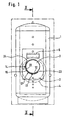
Figur 1- eine Vorderansicht eines erfindungsgemäßen Heizkessels und
Figur 2- einen Schnitt gemäß Linie II-II in
Figur 1, in gegenüberFigur 1 vergrößertem Maßstab.
- Figure 1
- a front view of a boiler according to the invention and
- Figure 2
- a section along line II-II in Figure 1, on an enlarged scale compared to Figure 1.
Ein mit Wasser gefüllter Heizkessel 1 zur Aufbereitung von
Warmwasser für Heizungsanlagen und den sanitären Bereich
weist zentral einen Ölbrenner 2 mit einer Brennkammer 3 und
einer an der Front des Heizkessels 1 angeordneten Abdeckhaube
4 auf. Im Heizkessel 1 über der Brennkammer 3 ist ein
Rauchgas-Abzug 6 angeordnet, durch den das bei der Verbrennung
entstehende Rauchgas zum Kamin abziehen kann. Im Heizkessel
1 können neben dem Ölbrenner 2 auch Wärmetauscher
oder Boiler vorgesehen sein, insbesondere oberhalb und unterhalb
der Brennkammer 3, wie dies in Figur 2 gezeigt ist.A
Die Brennkammer 3 besitzt einen kreisförmigen Querschnitt
und ist im wesentlichen zylinderförmig ausgebildet. An ihrer
Oberseite besitzt die Brennkammer 3 Abzugsöffnungen 7, durch
die das Rauchgas zum Rauchgas-Abzug 6 gelangen kann. Die
Brennkammer 3 ist an der vorderen Seite des Heizkessels 1
über Haltevorrichtungen 8, 9 am Heizkessel 1 befestigt. Zwischen
den Haltevorrichtungen 8, 9 weist die Brennkammer 3
eine Öffnung 11 auf, durch welche die Spitze des Ölbrenners
2 in die Brennkammer 3 einführbar ist. Die Brennkammer 3
kann aber auch an einem Wärmespeicher der Heizanlage oder an
dem Heizkessel 1 angeschweißt sein.The
Die Brennkammer 3 ist in geringem Abstand zu ihrer Außenwand
12 im Bereich der Unterseite 13 und einer Seitenwand 14 der
Brennkammer von einer Wandung 16 umgeben, die entsprechend
der Kreiszylinderform der Brennkammer 3 als schalenförmiger
Halbzylinder 17 ausgebildet ist. Der Halbzylinder 17 hat
dabei einen Querschnitt, der einem Kreissegment entspricht.
Das Kreissegment kann bei anderen Ausführungsformen auch
kleiner oder größer als ein Halbkreis sein. Der Halbzylinder
17 ist über Haltevorrichtungen 18 an der Vorderseite des
Heizkessels 1 unabhängig von der Brennkammer 3 befestigt.
Der Halbzylinder 17 kann aber auch an der Vorderseite des
Heizkessels 1 oder an einem Wärmespeicher der Heizanlage
angeschweißt sein. Der Halbzylinder 17 ist dabei in axialer
Richtung so lang ausgeführt, daß die Wandung 16 bis über das
hintere Ende 21 der Brennkammer 3 hinausragt. Auf diese Weise
wird über die gesamte Länge der Brennkammer 3 ein Zwischenraum
22 zwischen Brennkammer 3 und Halbzylinder 17 gebildet,
der im Bereich der Endabschnitte 23 und 24 des Halbzylinders
17 mit dem Innenraum des Heizkessels 1 in Verbindung
steht. Das in dem Behälter 1 vorhandene Speicherwasser
kann dadurch im Bereich des tiefer liegenden Endabschnittes
23 in den Zwischenraum 22 eintreten und diesen im Bereich
des Endabschnittes 24 wieder verlassen.The
Das den Zwischenraum 22 durchströmende Speicherwasser wird
durch die Brennkammer 3 erhitzt und bildet ein Wärmepolster
gegenüber dem übrigen im Behälter 1 vorhandenen Speicherwasser.
Die Temperatur der Wand 12 der Brennkammer 3 ist dadurch
im Bereich der Wandung 16 verhältnismäßig hoch und
liegt insbesondere auf einer Temperatur, bei der praktisch
keine Schwitzwasserbildung stattfindet.The storage water flowing through the
Als Halbzylinder 17 kann insbesondere ein einfaches Metallblech
dienen, welches kostengünstig herstellbar und leicht
zu montieren ist. Durch die Erfindung kann somit auf besonders
günstige Weise die Entstehung von Schwitzwasser unterbunden
und dadurch eine Korrosion der Brennkammer 3 weitgehend
verhindert werden.A simple metal sheet can in particular be used as the
Claims (7)
- A heating system comprising a tank (1) serving as a heat store and filled with water as a heat storage medium and a combustion chamber (3) with a circular cross-section present in the tank (1) for the heating of the storage water by combustion of a fuel, with the combustion chamber (3) being surrounded at a small spacing at least at its lower side by a wall (16) partly circular in cross-section and with the space formed between the combustion chamber (3) and the wall (16) being open towards the tank (1),
characterised in that the wall (16) is upwardly drawn up to over half the height of the combustion chamber (3) at only one side of the combustion chamber (3) and in that the wall (16) is upwardly drawn further at this side of the combustion chamber (3) than at the side of the combustion chamber (3) opposite thereto. - A heating system in accordance with claim 1, characterised in that the spacing between the wall (16) and the combustion chamber (3) amounts to between approximately 2 mm and approximately 5 mm.
- A heating system in accordance with any one of the preceding claims, characterised in that the combustion chamber (3) is made as a so-called low NOx combustion chamber.
- A heating system in accordance with claim 3, characterised in that the combustion chamber (3) is made as a so-called three pass boiler.
- A heating system in accordance with any one of the preceding claims, characterised in that the tank (1) can be connected to radiators via forward flow lines and return flow lines (26, 27) in the circuit and in that at least one upper throughflow heat exchanger (28) arranged in the upper region of the tank (1) is provided for the heating of fresh water and is arranged in series with a lower throughflow heat exchanger (29) provided in the lower region of the tank (1) for the pre-heating of the fresh water, with the combustion chamber (3) being arranged between the upper throughflow heat exchanger (28) and the lower throughflow heat exchanger (29).
- A heating system in accordance with claim 5, characterised in that at least one vertical shaft (31, 32) is respectively present in the region of the upper throughflow heat exchanger (28) and/ or in the region of the lower throughflow heat exchanger (29).
- A heating system in accordance with claim 6, characterised in that the lower opening (33) of the upper shaft (31) is arranged above the combustion chamber (3).
Applications Claiming Priority (2)
| Application Number | Priority Date | Filing Date | Title |
|---|---|---|---|
| DE29622446U DE29622446U1 (en) | 1996-12-31 | 1996-12-31 | Heating system |
| DE29622446U | 1996-12-31 |
Publications (3)
| Publication Number | Publication Date |
|---|---|
| EP0851180A2 EP0851180A2 (en) | 1998-07-01 |
| EP0851180A3 EP0851180A3 (en) | 1999-11-17 |
| EP0851180B1 true EP0851180B1 (en) | 2004-01-14 |
Family
ID=8033819
Family Applications (1)
| Application Number | Title | Priority Date | Filing Date |
|---|---|---|---|
| EP97113483A Expired - Lifetime EP0851180B1 (en) | 1996-12-31 | 1997-08-05 | Heating installation |
Country Status (3)
| Country | Link |
|---|---|
| EP (1) | EP0851180B1 (en) |
| AT (1) | ATE257933T1 (en) |
| DE (2) | DE29622446U1 (en) |
Families Citing this family (1)
| Publication number | Priority date | Publication date | Assignee | Title |
|---|---|---|---|---|
| CN108826683B (en) * | 2018-08-29 | 2023-08-08 | 浙江格洛维能源科技有限公司 | High-carbon molecular heating oil electric water heater with internal and external spiral heat exchange structure |
Family Cites Families (4)
| Publication number | Priority date | Publication date | Assignee | Title |
|---|---|---|---|---|
| DE7508469U (en) * | 1975-03-18 | 1977-05-05 | Viessmann, Hans, 3559 Battenberg | DEVICE FOR GENERATING HOT WATER |
| DE3412331C1 (en) * | 1984-04-03 | 1985-10-31 | Interdomo GmbH & Co Heizungs- und Wärmetechnik, 4407 Emsdetten | Heating boiler for low-temperature heating systems |
| FR2629907A1 (en) * | 1988-04-06 | 1989-10-13 | Collard A Trolart G | Improvements to heat exchangers |
| DD280375A1 (en) * | 1989-03-02 | 1990-07-04 | Ve Kom Haus U Kuechengeraete S | HOT WATER PREPARATION WITH LINE DEVICE |
-
1996
- 1996-12-31 DE DE29622446U patent/DE29622446U1/en not_active Expired - Lifetime
-
1997
- 1997-08-05 DE DE59711213T patent/DE59711213D1/en not_active Expired - Fee Related
- 1997-08-05 AT AT97113483T patent/ATE257933T1/en not_active IP Right Cessation
- 1997-08-05 EP EP97113483A patent/EP0851180B1/en not_active Expired - Lifetime
Also Published As
| Publication number | Publication date |
|---|---|
| EP0851180A2 (en) | 1998-07-01 |
| DE59711213D1 (en) | 2004-02-19 |
| ATE257933T1 (en) | 2004-01-15 |
| DE29622446U1 (en) | 1997-03-06 |
| EP0851180A3 (en) | 1999-11-17 |
Similar Documents
| Publication | Publication Date | Title |
|---|---|---|
| CH616499A5 (en) | Central heating system with a boiler and an additional heat exchanger for preheating the medium flowing back to the boiler | |
| DE2102024C3 (en) | Steam generator | |
| EP0851180B1 (en) | Heating installation | |
| LU82314A1 (en) | TWO-CHAMBER BOILER FOR BURNER AND SOLID FUEL BURNER | |
| EP0275401B1 (en) | Heater and process for operating this heater | |
| DE3238603C2 (en) | ||
| EP0166703B1 (en) | Heater | |
| DE624892C (en) | Water-cooled moving grate | |
| DE3108452C2 (en) | Oil / gas boilers | |
| EP0031571B1 (en) | Boiler | |
| EP0217320A2 (en) | Heater for liquid or gaseous combustibles | |
| DE3221724C2 (en) | FRYING, BAKING AND / OR COOKING EQUIPMENT | |
| DE3111084A1 (en) | Hearth | |
| DE3044088C2 (en) | Furnace for heating a fluid, in particular water or air | |
| DE3231211A1 (en) | Device for a combustion chamber with an oil or gas burner | |
| EP0319009B1 (en) | Boiler | |
| DE4111232C2 (en) | ||
| DE2227070C3 (en) | Boiler system for hot water heating | |
| DE6610039U (en) | FLAME PIPE SMOKE PIPE BOILERS, ESPECIALLY WITH OIL OR GAS FIRING. | |
| EP0059898A2 (en) | Method for using a hot water central heating system with a separated flue gas heat exchanger | |
| AT393023B (en) | Heating system | |
| AT204741B (en) | Central heating boiler | |
| DE2933911A1 (en) | Return flow water heating system - has heat exchanger installed between combustion chamber and chimney for initial re-heating of water | |
| DE19947294A1 (en) | Central heating fluid fuel burning boiler has a circulating flue gas arrangement to reduce the flue gas outer casing temperatures | |
| DE6607833U (en) | HIGH PRESSURE HEATED BOILER WITH MULTIPLE SMOKE CONDUCTIONS BETWEEN TWO MOUNTAINS. |
Legal Events
| Date | Code | Title | Description |
|---|---|---|---|
| PUAI | Public reference made under article 153(3) epc to a published international application that has entered the european phase |
Free format text: ORIGINAL CODE: 0009012 |
|
| AK | Designated contracting states |
Kind code of ref document: A2 Designated state(s): AT CH DE FR IT LI |
|
| AX | Request for extension of the european patent |
Free format text: AL;LT;LV;RO;SI |
|
| PUAL | Search report despatched |
Free format text: ORIGINAL CODE: 0009013 |
|
| AK | Designated contracting states |
Kind code of ref document: A3 Designated state(s): AT BE CH DE DK ES FI FR GB GR IE IT LI LU MC NL PT SE |
|
| AX | Request for extension of the european patent |
Free format text: AL;LT;LV;RO;SI |
|
| AKX | Designation fees paid | ||
| 17P | Request for examination filed |
Effective date: 20000517 |
|
| RBV | Designated contracting states (corrected) |
Designated state(s): AT CH DE FR IT LI |
|
| REG | Reference to a national code |
Ref country code: DE Ref legal event code: 8566 |
|
| 17Q | First examination report despatched |
Effective date: 20020313 |
|
| GRAH | Despatch of communication of intention to grant a patent |
Free format text: ORIGINAL CODE: EPIDOS IGRA |
|
| GRAS | Grant fee paid |
Free format text: ORIGINAL CODE: EPIDOSNIGR3 |
|
| GRAA | (expected) grant |
Free format text: ORIGINAL CODE: 0009210 |
|
| AK | Designated contracting states |
Kind code of ref document: B1 Designated state(s): AT CH DE FR IT LI |
|
| REG | Reference to a national code |
Ref country code: CH Ref legal event code: EP |
|
| REF | Corresponds to: |
Ref document number: 59711213 Country of ref document: DE Date of ref document: 20040219 Kind code of ref document: P |
|
| ET | Fr: translation filed | ||
| PLBE | No opposition filed within time limit |
Free format text: ORIGINAL CODE: 0009261 |
|
| STAA | Information on the status of an ep patent application or granted ep patent |
Free format text: STATUS: NO OPPOSITION FILED WITHIN TIME LIMIT |
|
| 26N | No opposition filed |
Effective date: 20041015 |
|
| PGFP | Annual fee paid to national office [announced via postgrant information from national office to epo] |
Ref country code: FR Payment date: 20050825 Year of fee payment: 9 |
|
| PGFP | Annual fee paid to national office [announced via postgrant information from national office to epo] |
Ref country code: IT Payment date: 20060831 Year of fee payment: 10 |
|
| REG | Reference to a national code |
Ref country code: FR Ref legal event code: ST Effective date: 20070430 |
|
| PG25 | Lapsed in a contracting state [announced via postgrant information from national office to epo] |
Ref country code: FR Free format text: LAPSE BECAUSE OF NON-PAYMENT OF DUE FEES Effective date: 20060831 |
|
| PGFP | Annual fee paid to national office [announced via postgrant information from national office to epo] |
Ref country code: AT Payment date: 20080829 Year of fee payment: 12 |
|
| PGFP | Annual fee paid to national office [announced via postgrant information from national office to epo] |
Ref country code: DE Payment date: 20081030 Year of fee payment: 12 Ref country code: CH Payment date: 20081127 Year of fee payment: 12 |
|
| PG25 | Lapsed in a contracting state [announced via postgrant information from national office to epo] |
Ref country code: IT Free format text: LAPSE BECAUSE OF NON-PAYMENT OF DUE FEES Effective date: 20070805 |
|
| REG | Reference to a national code |
Ref country code: CH Ref legal event code: PL |
|
| PG25 | Lapsed in a contracting state [announced via postgrant information from national office to epo] |
Ref country code: LI Free format text: LAPSE BECAUSE OF NON-PAYMENT OF DUE FEES Effective date: 20090831 Ref country code: CH Free format text: LAPSE BECAUSE OF NON-PAYMENT OF DUE FEES Effective date: 20090831 |
|
| PG25 | Lapsed in a contracting state [announced via postgrant information from national office to epo] |
Ref country code: AT Free format text: LAPSE BECAUSE OF NON-PAYMENT OF DUE FEES Effective date: 20090805 |
|
| PG25 | Lapsed in a contracting state [announced via postgrant information from national office to epo] |
Ref country code: DE Free format text: LAPSE BECAUSE OF NON-PAYMENT OF DUE FEES Effective date: 20100302 |