EP0851151A1 - Pulley and manufacturing method of the same - Google Patents

Pulley and manufacturing method of the same Download PDF

Info

Publication number
EP0851151A1
EP0851151A1 EP97310601A EP97310601A EP0851151A1 EP 0851151 A1 EP0851151 A1 EP 0851151A1 EP 97310601 A EP97310601 A EP 97310601A EP 97310601 A EP97310601 A EP 97310601A EP 0851151 A1 EP0851151 A1 EP 0851151A1
Authority
EP
European Patent Office
Prior art keywords
section
web
pulley
inner cylindrical
cylindrical section
Prior art date
Legal status (The legal status is an assumption and is not a legal conclusion. Google has not performed a legal analysis and makes no representation as to the accuracy of the status listed.)
Withdrawn
Application number
EP97310601A
Other languages
German (de)
French (fr)
Inventor
Masakiyo Ohya
Current Assignee (The listed assignees may be inaccurate. Google has not performed a legal analysis and makes no representation or warranty as to the accuracy of the list.)
Jtekt Column Systems Corp
Original Assignee
Fuji Kiko Co Ltd
Priority date (The priority date is an assumption and is not a legal conclusion. Google has not performed a legal analysis and makes no representation as to the accuracy of the date listed.)
Filing date
Publication date
Application filed by Fuji Kiko Co Ltd filed Critical Fuji Kiko Co Ltd
Publication of EP0851151A1 publication Critical patent/EP0851151A1/en
Withdrawn legal-status Critical Current

Links

Images

Classifications

    • BPERFORMING OPERATIONS; TRANSPORTING
    • B21MECHANICAL METAL-WORKING WITHOUT ESSENTIALLY REMOVING MATERIAL; PUNCHING METAL
    • B21HMAKING PARTICULAR METAL OBJECTS BY ROLLING, e.g. SCREWS, WHEELS, RINGS, BARRELS, BALLS
    • B21H1/00Making articles shaped as bodies of revolution
    • B21H1/02Making articles shaped as bodies of revolution discs; disc wheels
    • B21H1/04Making articles shaped as bodies of revolution discs; disc wheels with rim, e.g. railways wheels or pulleys
    • BPERFORMING OPERATIONS; TRANSPORTING
    • B21MECHANICAL METAL-WORKING WITHOUT ESSENTIALLY REMOVING MATERIAL; PUNCHING METAL
    • B21KMAKING FORGED OR PRESSED METAL PRODUCTS, e.g. HORSE-SHOES, RIVETS, BOLTS OR WHEELS
    • B21K1/00Making machine elements
    • B21K1/28Making machine elements wheels; discs
    • B21K1/42Making machine elements wheels; discs pulleys, e.g. cable pulleys

Definitions

  • This invention relates to a pulley having V-shaped grooves on its outer circumference and relates to a manufacturing method of the same.
  • a pulley which was obtained by working a thin iron plate for example, is known. Namely, this pulley is arranged so that a cylindrical bearing section (inner cylindrical section) 1, a web section 2 and a rim section (outer cylindrical section) 3 are formed by bending an iron plate provided as a material by press, etc., and that a plurality of V-shaped grooves 4 are formed on the outer circumference of the rim section 3.
  • the web section 2 is formed by bending the iron plate, one end portions of the bearing section 1 and rim section 3 in the axial direction are cantilevered. Moreover, the V-shaped grooves 4 are formed on the outer circumference of the rim section 3 by compressing the rim section 3 in the axial direction and enlarging its thickness.
  • the bearing section 1 is arranged so that its inner circumferential surface is engaged with a bearing 5.
  • the present invention has been achieved with such points in view.
  • a first aspect of the invention provides a pulley comprising; an inner cylindrical section, a web section which is extended from a central portion in an axial direction of the inner cylindrical section, an outer cylindrical section which is formed at an outer circumferential portion of the web section coaxially with respect to the inner cylindrical section about the web section, and V-shaped grooves which are formed on an outer circumference of the outer cylindrical section are formed integrally by cold working.
  • the web section is formed so that its thickness becomes thicker gradually with directing towards the inner cylindrical section and outer cylindrical section.
  • the inner cylindrical section is formed with a bearing stopper.
  • a fourth aspect of the invention provides a manufacturing method of a pulley, comprising the steps of: forming a web section on a middle portion in a radial direction of a thick ring body by crushing the middle portion by cold working, forming an inner cylindrical section at an inner circumferential portion of the web section, a central portion of the inner cylindrical section being the web section, forming a redundant section at the outer circumferential portion of the web section, a central portion of the redundant section being the web section, and forming an outer cylindrical section having V-shaped grooves on its outer circumferential portion, the outer cylindrical section being formed at the outer circumferential portion of the web section coaxially with respect to the inner cylindrical section about the web section by cold-working V-shaped grooves on an outer circumference of the redundant section.
  • the thick ring body is formed such that a thick circulate plate body is formed by crushing a cylindrical material by cold working, that a circular thin section is formed by crushing a central portion of the thick circular plate body in a circular shape by cold working, and that the circular thin section is blanked by press.
  • the thick ring body is formed by blanking a plate shaped material by press.
  • the web section is formed by crushing a central portion in a radial direction of the thick ring body by cold working so that its thickness becomes thicker gradually with directing towards the inner cylindrical section and outer cylindrical section.
  • the web section connects the central portion of the inner cylindrical section with the central portion of the outer cylindrical portion, even if tension of the belt is applied to the V-shaped grooves, bending moment generated by the tension is small. Further, since the tension is applied to the outer cylindrical section symmetrically with respect to the web section, the bending moment can be prevented from being applied to the web section and inner cylindrical section. Therefore, the whole portion is extremely difficult to deflect, so vibration and noise due to the deflection can be reduced, and the durability can be improved.
  • the web section is formed so that its thickness becomes thicker gradually with directing towards the inner cylindrical section and outer cylindrical section, rigidity of a connecting portion between the web section and inner cylindrical section and a connecting portion between the web section and outer cylindrical section can be improved, and strength and durability can be improved.
  • the pulley has an integral bearing stopper.
  • the durability can be improved.
  • the thickness of the whole portion can be thin, light-weighting and miniaturization can be realized.
  • the finishing step for example, can be omitted, and the cost can be reduced.
  • the outer cylindrical section can be formed so as to have an enough thickness to form V-shaped grooves as a redundant section, the step of increasing a thickness which is shown in the conventional example is not required. Therefore, the manufacturing steps can be simplified, and the productivity can be improved and the cost can be reduced.
  • the thick ring body is formed by cold-working a cylindrical material, yield is improved by cold forging, and material costs can be reduced, thereby making it possible to reduce the cost.
  • the thick ring body is formed by blanking a plate-shaped material by press, the productivity can be improved, and the cost can be reduced.
  • the seventh aspect when the web section is cold-worked, a material positioned in the web section is easy to flow to the inner cylindrical section and outer cylindrical section. Therefore, a force and time required for the cold working can be reduced.
  • FIGs. 2 through 9 show the first embodiment
  • FIGs. 10 through 12 show the second embodiment
  • FIGs. 13 through 16 show the third embodiment
  • FIGs. 17 and 18 show the fourth embodiment.
  • a pulley 10 in the first embodiment is obtained by forming a bearing section (inner cylindrical section) 11 formed in a cylindrical shape, a web section 12 which is extended from a central portion of the bearing section 11 in the axial direction to the outside radially, a cylindrical rim section (outer cylindrical section) 13 which is formed at the outer circumferential portion of the web section 12 coaxially with respect to the bearing section 11 about the web section 12, and V-shaped grooves 14 which are formed on the outer circumference of the rim section 13.
  • the bearing section 11, web section 12, rim section 13 and V-shaped grooves 14 are formed integrally by cold working.
  • a plurality of the V-shaped grooves 14 are so-called poly-V-shaped grooves.
  • the respective V-shaped grooves 14 are formed symmetrically with respect to the web section 12.
  • the inner circumferential surface of the bearing section 11 is engaged with a bearing (not shown) similarly to the conventional example.
  • a cylindrical iron material W1 shown in FIG. 3 is cold-forged (cold-worked) by press so that a thick circular plate W2 shown in FIG. 4 is formed.
  • a central portion of the thick circular plate W2 is crushed in a circular shape from the top and bottom surfaces by the cold forging using press, and a circular thin section W2a is formed.
  • the circular thin section W2 is blanked by press so that a thick ring body W3 is formed.
  • a middle portion of the thick ring body W3 in a radial direction is crushed from the top and bottom surfaces by the cold forging using press so that the bearing section 1 1 is formed on the inner circumference of the thick ring body W3, the web section 12 is formed on the middle portion and a redundant section W4a used for forming the rim section 13 is formed on the outer circumference.
  • a rough shaped section W4 of the pulley is formed.
  • the rough shaped section W4 is cold-forged by a bottom die M1, top die M2, inner circumference holding die M3 and outer circumference holding die M4.
  • the rim section 13 can be formed so as to have an enough thickness to form the V-shaped groove 14 as the redundant section W4a, the step of increasing a thickness in the conventional example is not required. Therefore, the cost can be reduced. Moreover, since the yield is improved by the cold forging, the material costs can be reduced.
  • an annular stopper 11a which is bent from one end in its axial direction towards the inner side is formed at the bearing section 11.
  • the stopper 11a is formed by cold forging at the step of forming the rough shaped section W4 of the pulley.
  • the rim section 13 and V-shaped grooves 14 are formed by the roller die M8 with the bearing section 11 including the stopper 11a and the web section 12 being held by the dies M5, M6 and M7.
  • the pulley 10 structured in the above manner since the rough shaped section W4 of the pulley can be formed by the cold forging and at the same time the inner surface of the bearing section 11 and the stopper 11a can be formed accurately, a bearing is engaged directly with the bearing section 11, and the bearing can be positioned. Therefore, the productivity can be improved.
  • a point of the third embodiment which is different from the first embodiment is that the thickness of the web section 12 becomes thicker gradually with directing towards the bearing section 11 and the rim section 13.
  • the web section 12 is formed so that its thickness becomes thicker gradually with directing towards the bearing section 11 and rim section 13 on a circularly arced surface.
  • the web section 12 formed in such a manner, as shown in FIG. 15, is formed by cold forging at the step of forming the rough shaped section W4 of the pulley.
  • the material positioned in the web section 12 is easy to flow to the sides of the bearing section 11 and rim section 13.
  • the rim section 13 and V-shaped grooves 14 are formed by the roller die M8 with the bearing section 11 and web section 12 being held by the dies M5, M6 and M7.
  • the web section 12 is formed so that its thickness becomes thicker gradually with directing towards the bearing section 11 and rim section 13 on a circularly arced surface, when the web section 12 is cold-forged, the material positioned in the web section 12 is easy to flow towards the bearing section 11 and rim section 13. Therefore, a force and time required for cold forging can be reduced. Moreover, since the thickness of a portion requiring strength can be increased easily and the thickness of a portion which does not require strength can be reduced easily, the strength and light-weighting of the pulley 10 can be improved.
  • a plurality of the V-shaped grooves 14 are provided, but only one V-shaped groove 14, namely, a so-called mono-V-shaped groove may be provided.
  • the mono-V-shaped groove is formed symmetrically with respect to the web section 12.
  • the V-shaped grooves 14 may be arranged by combining the mono-V-shaped groove and poly-V-shaped groove. Namely, both the mono-V-shaped groove and poly-V-shaped groove may be provided to the rim section 13.
  • a stopper for a bearing may be provided.
  • a point of the fourth embodiment different from the first embodiment is that the thick ring body W3 is formed by pressing a plate-shaped material W0.
  • the ring-shaped thick ring body W2 is formed by blanking the thick plate-shaped material W0 by press.
  • the rough shaped section W4 of the pulley is formed. Since the forming structure hereafter is the same as that in the first embodiment, the description thereof is omitted.
  • the thick ring body W2 can be formed by blanking the plate-shaped material W0 by press, the thick ring body W2 can be formed only by press. As a result, the manufacturing steps can be simplified, the productivity can be improved, and thus the cost can be reduced.
  • the thick circular plate body W2 obtained when the thick ring body is formed may be broken as scrap, but similarly to the thick circulate plate body W2 shown in the first embodiment, after the central portion of the thick circulate plate body W2 is crushed from the top and bottom surfaces in a circulate shape by cold forging using press and a circular thin section W2a is formed, the thick ring body W3 is formed by blanking the circular thin section W2a using press so as to be used. As a result, the material can be used effectively, and thus the cost can be reduced.

Landscapes

  • Engineering & Computer Science (AREA)
  • Mechanical Engineering (AREA)
  • Pulleys (AREA)
  • Forging (AREA)

Abstract

A web section (12) extends from a central portion in an axial direction of an inner cylindrical section (11), an outer cylindrical section (13) is formed at an outer circumferential portion of the web section (12), coaxially with respect to the inner cylindrical section (11) about the web section (12), and V-shaped grooves (14) are formed on an outer circumference of the outer cylindrical section (13), integrally by a cold working.

Description

BACKGROUND OF THE INVENTION 1. Field of the Invention
This invention relates to a pulley having V-shaped grooves on its outer circumference and relates to a manufacturing method of the same.
2. Description of Relevant Art
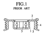
As shown in FIG. 1, a pulley which was obtained by working a thin iron plate, for example, is known. Namely, this pulley is arranged so that a cylindrical bearing section (inner cylindrical section) 1, a web section 2 and a rim section (outer cylindrical section) 3 are formed by bending an iron plate provided as a material by press, etc., and that a plurality of V-shaped grooves 4 are formed on the outer circumference of the rim section 3.
Since the web section 2 is formed by bending the iron plate, one end portions of the bearing section 1 and rim section 3 in the axial direction are cantilevered. Moreover, the V-shaped grooves 4 are formed on the outer circumference of the rim section 3 by compressing the rim section 3 in the axial direction and enlarging its thickness. Here, the bearing section 1 is arranged so that its inner circumferential surface is engaged with a bearing 5.
In the conventional pulley, tension of a belt in the V-shaped grooves 4 is applied to the rim section 3. However, since one end of the rim section 3 in the axial direction is cantilevered by the web section 2, when the tension is applied thereto from the belt, strong bending moment is applied to the rim section 3, web section 2 and bearing section 1. For this reason, there arose problems such that since the whole portion was easily deflected, vibration and noise occurred easily, and durability is deteriorated. Moreover, since the pulley is formed by using a thin plate, when the V-shaped grooves 4 are formed, the thickness of the rim section 3 should be increased. For this reason, there arose a problem such that manufacturing cost was increased due to the process of increasing the thickness.
SUMMARY OF THE INVENTION
The present invention has been achieved with such points in view.
It therefore is an object of the present invention to provide a pulley which is capable of reducing vibration and noise, improving durability and reducing the manufacturing cost and to provide a manufacturing method thereof.
To achieve the object, a first aspect of the invention provides a pulley comprising; an inner cylindrical section, a web section which is extended from a central portion in an axial direction of the inner cylindrical section, an outer cylindrical section which is formed at an outer circumferential portion of the web section coaxially with respect to the inner cylindrical section about the web section, and V-shaped grooves which are formed on an outer circumference of the outer cylindrical section are formed integrally by cold working.
According to a second aspect of the invention, the web section is formed so that its thickness becomes thicker gradually with directing towards the inner cylindrical section and outer cylindrical section.
According to a third aspect of the invention, the inner cylindrical section is formed with a bearing stopper.
Further, to achieve the object described, a fourth aspect of the invention provides a manufacturing method of a pulley, comprising the steps of: forming a web section on a middle portion in a radial direction of a thick ring body by crushing the middle portion by cold working, forming an inner cylindrical section at an inner circumferential portion of the web section, a central portion of the inner cylindrical section being the web section, forming a redundant section at the outer circumferential portion of the web section, a central portion of the redundant section being the web section, and forming an outer cylindrical section having V-shaped grooves on its outer circumferential portion, the outer cylindrical section being formed at the outer circumferential portion of the web section coaxially with respect to the inner cylindrical section about the web section by cold-working V-shaped grooves on an outer circumference of the redundant section.
According a fifth aspect of the invention, the thick ring body is formed such that a thick circulate plate body is formed by crushing a cylindrical material by cold working, that a circular thin section is formed by crushing a central portion of the thick circular plate body in a circular shape by cold working, and that the circular thin section is blanked by press.
According to a sixthth aspect of the invention, the thick ring body is formed by blanking a plate shaped material by press.
According to a seventh aspect of the invention, the web section is formed by crushing a central portion in a radial direction of the thick ring body by cold working so that its thickness becomes thicker gradually with directing towards the inner cylindrical section and outer cylindrical section.
In the invention according to the first aspect arranged in the above manner, since the web section connects the central portion of the inner cylindrical section with the central portion of the outer cylindrical portion, even if tension of the belt is applied to the V-shaped grooves, bending moment generated by the tension is small. Further, since the tension is applied to the outer cylindrical section symmetrically with respect to the web section, the bending moment can be prevented from being applied to the web section and inner cylindrical section. Therefore, the whole portion is extremely difficult to deflect, so vibration and noise due to the deflection can be reduced, and the durability can be improved.
According to the second aspect, since the web section is formed so that its thickness becomes thicker gradually with directing towards the inner cylindrical section and outer cylindrical section, rigidity of a connecting portion between the web section and inner cylindrical section and a connecting portion between the web section and outer cylindrical section can be improved, and strength and durability can be improved.
According to the third aspect, the pulley has an integral bearing stopper.
According to the fourth aspect, since a layered structure is obtained by cold working and the strength is increased by hardening due to the cold working, the durability can be improved. Moreover, since the thickness of the whole portion can be thin, light-weighting and miniaturization can be realized. Further, since the surface accuracy is improved by the cold working, the finishing step, for example, can be omitted, and the cost can be reduced.
Furthermore, in the cold working step, since the outer cylindrical section can be formed so as to have an enough thickness to form V-shaped grooves as a redundant section, the step of increasing a thickness which is shown in the conventional example is not required. Therefore, the manufacturing steps can be simplified, and the productivity can be improved and the cost can be reduced.
According to the fifth aspect , since the thick ring body is formed by cold-working a cylindrical material, yield is improved by cold forging, and material costs can be reduced, thereby making it possible to reduce the cost.
According to the sixth aspect, since the thick ring body is formed by blanking a plate-shaped material by press, the productivity can be improved, and the cost can be reduced.
According to the seventh aspect, when the web section is cold-worked, a material positioned in the web section is easy to flow to the inner cylindrical section and outer cylindrical section. Therefore, a force and time required for the cold working can be reduced.
BRIEF DESCRIPTION OF THE DRAWINGS
The above and further objects and novel features of the present invention will more fully appear from the following detailed description when the same is read in conjunction with the accompanying drawings, in which:
  • FIG. 1 is a sectional view showing a pulley as a conventional example;
  • FIG. 2 is a sectional view showing a pulley according to the first embodiment of the present invention;
  • FIG. 3 is a drawing showing a manufacturing method of the pulley, i.e., a side view showing a cylindrical material;
  • FIG. 4 is a drawing showing the manufacturing method of the pulley, i.e., a side view showing a thick circular plate;
  • FIG. 5 is a drawing showing the manufacturing method of the pulley, i.e., a sectional view showing a state that a thick circular portion is formed on the thick circular plate;
  • FIG. 6 is a drawing showing the manufacturing method of the pulley, i.e., a sectional view showing a thick ring body;
  • FIG. 7 is a drawing showing the manufacturing method of the pulley, i.e., a sectional view showing a rough shaped section of the pulley;
  • FIG. 8 is a drawing showing a forming unit of the pulley, i.e., a sectional view showing a unit for forming the rough shaped section of the pulley;
  • FIG. 9 is a drawing showing a forming unit of the pulley, i.e., a sectional view showing a unit for forming a rim section and V-shaped grooves;
  • FIG. 10 is a sectional view of the pulley according to the second embodiment of the present invention;
  • FIG. 11 is a drawing showing a forming unit of the pulley, i.e., a sectional view showing a unit for forming the rough shaped section of the pulley;
  • FIG. 12 is a drawing showing a forming unit of the pulley, i.e., a sectional view showing a unit for forming the rim section and V-shaped grooves;
  • FIG. 13 is a sectional view showing the rough shape section of the pulley according to the third embodiment of the present invention;
  • FIG. 14 is a sectional view showing the finished pulley;
  • FIG. 15 is a drawing showing a forming unit of the pulley, i.e., a sectional view showing a unit for forming the rough shaped section of the pulley;
  • FIG. 16 is a drawing showing a forming unit of the pulley, i.e., a sectional view showing a unit for forming the rim section and V-shaped grooves;
  • FIG. 17 is a perspective view showing a plate-shaped material used in the fourth embodiment of the present invention; and
  • FIG. 18 is a drawing showing the manufacturing method of the pulley, i.e., a perspective view showing a thick ring body.
  • DETAILED DESCRIPTION OF THE PREFERRED EMBODIMENTS
    There will be detailed below the preferred embodiments of the present invention with reference to FIGs. 2 through 16. Here, FIGs. 2 through 9 show the first embodiment, FIGs. 10 through 12 show the second embodiment, FIGs. 13 through 16 show the third embodiment, and FIGs. 17 and 18 show the fourth embodiment.
    First, the description will be given as to the first embodiment of the present invention on reference to FIGs. 2 through 9. Namely, a pulley 10 in the first embodiment, as shown in FIG. 2, is obtained by forming a bearing section (inner cylindrical section) 11 formed in a cylindrical shape, a web section 12 which is extended from a central portion of the bearing section 11 in the axial direction to the outside radially, a cylindrical rim section (outer cylindrical section) 13 which is formed at the outer circumferential portion of the web section 12 coaxially with respect to the bearing section 11 about the web section 12, and V-shaped grooves 14 which are formed on the outer circumference of the rim section 13. The bearing section 11, web section 12, rim section 13 and V-shaped grooves 14 are formed integrally by cold working.
    A plurality of the V-shaped grooves 14 are so-called poly-V-shaped grooves. The respective V-shaped grooves 14 are formed symmetrically with respect to the web section 12. Moreover, the inner circumferential surface of the bearing section 11 is engaged with a bearing (not shown) similarly to the conventional example.
    Next, the description will be given as to the manufacturing method of the aforementioned pulley 10 on reference to FIGs. 3 through 9. First, a cylindrical iron material W1 shown in FIG. 3 is cold-forged (cold-worked) by press so that a thick circular plate W2 shown in FIG. 4 is formed. Then, as shown in FIG. 5, a central portion of the thick circular plate W2 is crushed in a circular shape from the top and bottom surfaces by the cold forging using press, and a circular thin section W2a is formed. As shown in FIG. 6, the circular thin section W2 is blanked by press so that a thick ring body W3 is formed.
    Thereafter, as shown in FIG. 7, a middle portion of the thick ring body W3 in a radial direction is crushed from the top and bottom surfaces by the cold forging using press so that the bearing section 1 1 is formed on the inner circumference of the thick ring body W3, the web section 12 is formed on the middle portion and a redundant section W4a used for forming the rim section 13 is formed on the outer circumference. 
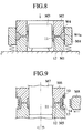
Namely, a rough shaped section W4 of the pulley is formed. As shown in FIG. 8, the rough shaped section W4 is cold-forged by a bottom die M1, top die M2, inner circumference holding die M3 and outer circumference holding die M4.
    Next, as shown in FIG. 9, while the bearing section 11 and web section 12 are being held by a lower surface holding die M5, upper surface holding die M6 and inner circumference holding die M7, the rim section 13 and V-shaped grooves 14 are rolled from the outer circumferential surface and cold-formed by using a roller die M8. As a result, the pulley 10 is finished.
    In the pulley 10 arranged in the above manner, since the web section 12 connects the central portion of the bearing section 11 to the central portion of the rim section 13, the tension of the belt is applied to the V-shaped grooves 14. As a result, even if bending moment is generated, the bending moment is weak. Furthermore, since the V-shaped grooves 14 are provided symmetrically with respect to the web section 12, the bending moment is balanced at the rim section 13. For this reason, the bending moment can be prevented from being applied to the web section 12 and bearing section 11. Therefore, the whole portion is difficult to deflect, and thus vibration and noise can be reduced, and durability of a bearing can be improved. Further, in this pulley 10, since a width between the bearing section 11 and the rim section 13 with which a bearing is engaged, i.e., a width of the web section 12 can be narrowed, an outer diameter of the rim section 13 can be small, and thus the pulley which is specially suitable to a pulley with small diameter can be obtained.
    In addition, since a layered structure is obtained by a series of cold working and strength is increased due to hardening by the cold forging, the durability can be further improved, and thus the thickness of the whole structure can be small. Therefore, the cost can be reduced. Further, since surface accuracy is improved by the cold forging, steps for finishing the inner surface of the bearing section 11 and the V-shaped grooves 14, for example, can be omitted, and this can also reduce the cost. Namely, the productivity can be improved.
    Furthermore, in the cold forging step, since the rim section 13 can be formed so as to have an enough thickness to form the V-shaped groove 14 as the redundant section W4a, the step of increasing a thickness in the conventional example is not required. Therefore, the cost can be reduced. Moreover, since the yield is improved by the cold forging, the material costs can be reduced.
    Next, the description will be given as to the second embodiment of the present invention on reference to FIGs. 10 through 12. However, the same reference numerals are given to the components which are common to the aforementioned first embodiment, and the description thereof is simplified. A point of the second embodiment different from the first embodiment is that a stopper 11a for a bearing is formed integrally with the bearing section 11.
    Namely, as shown in FIG. 10, an annular stopper 11a which is bent from one end in its axial direction towards the inner side is formed at the bearing section 11. As shown in FIG. 11, the stopper 11a is formed by cold forging at the step of forming the rough shaped section W4 of the pulley. Moreover, as shown in FIG. 12, the rim section 13 and V-shaped grooves 14 are formed by the roller die M8 with the bearing section 11 including the stopper 11a and the web section 12 being held by the dies M5, M6 and M7.
    In the pulley 10 structured in the above manner, since the rough shaped section W4 of the pulley can be formed by the cold forging and at the same time the inner surface of the bearing section 11 and the stopper 11a can be formed accurately, a bearing is engaged directly with the bearing section 11, and the bearing can be positioned. Therefore, the productivity can be improved.
    Next, the description will be given as to the third embodiment of the present invention on reference to FIGs. 13 through 16. However, the same reference numerals are given to the components which are common to the aforementioned first embodiment, and the description thereof is simplified. A point of the third embodiment which is different from the first embodiment is that the thickness of the web section 12 becomes thicker gradually with directing towards the bearing section 11 and the rim section 13.
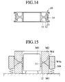
    Namely, as shown in FIGs. 13 and 14, the web section 12 is formed so that its thickness becomes thicker gradually with directing towards the bearing section 11 and rim section 13 on a circularly arced surface.
    The web section 12 formed in such a manner, as shown in FIG. 15, is formed by cold forging at the step of forming the rough shaped section W4 of the pulley. When the web section 12 is cold-forged, the material positioned in the web section 12 is easy to flow to the sides of the bearing section 11 and rim section 13. Moreover, as shown in FIG. 16, the rim section 13 and V-shaped grooves 14 are formed by the roller die M8 with the bearing section 11 and web section 12 being held by the dies M5, M6 and M7.
    In the pulley 10 structured in the above manner, since the web section 12 is formed so that its thickness becomes thicker gradually with directing towards the bearing section 11 and rim section 13 on a circularly arced surface, when the web section 12 is cold-forged, the material positioned in the web section 12 is easy to flow towards the bearing section 11 and rim section 13. Therefore, a force and time required for cold forging can be reduced. Moreover, since the thickness of a portion requiring strength can be increased easily and the thickness of a portion which does not require strength can be reduced easily, the strength and light-weighting of the pulley 10 can be improved.
    In the aforementioned embodiments, a plurality of the V-shaped grooves 14 are provided, but only one V-shaped groove 14, namely, a so-called mono-V-shaped groove may be provided. However, it is preferable that the mono-V-shaped groove is formed symmetrically with respect to the web section 12. Further, the V-shaped grooves 14 may be arranged by combining the mono-V-shaped groove and poly-V-shaped groove. Namely, both the mono-V-shaped groove and poly-V-shaped groove may be provided to the rim section 13.
    In addition, also in the third embodiment, a stopper for a bearing may be provided.
    Next, the description will be given as to the fourth embodiment of the present invention on reference to FIGs. 17 and 18. However, the same reference numerals are given to the components which are common to the first embodiment, and the description 
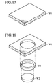
thereof is omitted. A point of the fourth embodiment different from the first embodiment is that the thick ring body W3 is formed by pressing a plate-shaped material W0.
    As shown in FIG. 18, the ring-shaped thick ring body W2 is formed by blanking the thick plate-shaped material W0 by press. When a middle portion in the radial direction of the thick ring body W2 is crushed in the similar manner to the first embodiment, the rough shaped section W4 of the pulley is formed. Since the forming structure hereafter is the same as that in the first embodiment, the description thereof is omitted.
    According to the fourth embodiment, since the thick ring body W2 can be formed by blanking the plate-shaped material W0 by press, the thick ring body W2 can be formed only by press. As a result, the manufacturing steps can be simplified, the productivity can be improved, and thus the cost can be reduced.
    Here, the thick circular plate body W2 obtained when the thick ring body is formed may be broken as scrap, but similarly to the thick circulate plate body W2 shown in the first embodiment, after the central portion of the thick circulate plate body W2 is crushed from the top and bottom surfaces in a circulate shape by cold forging using press and a circular thin section W2a is formed, the thick ring body W3 is formed by blanking the circular thin section W2a using press so as to be used. As a result, the material can be used effectively, and thus the cost can be reduced.
    While preferred embodiments of the present invention have been described using specific terms, such description is for illustrative purposes, and it is to be understood that changes and variations may be made without departing from the spirit or scope of the following claims.

    Claims (9)

    1. A pulley comprising:
      an inner cylindrical section;
      a web section which is extended from a central portion in an axial direction of said inner cylindrical section;
      an outer cylindrical section which is formed at an outer circumferential portion of said web section coaxially with respect to said inner cylindrical section about said web section; and
      V-shaped grooves which are formed on an outer circumference of said outer cylindrical section are formed integrally by cold working.
    2. The pulley according to claim 1, wherein said web section is formed so that its thickness becomes thicker gradually with directing towards said inner cylindrical section and outer cylindrical section.
    3. The pulley according to claim 1, wherein the inner cylindrical section is formed with a bearing stopper.
    4. A manufacturing method of a pulley, comprising the steps of:
      forming a web section on a middle portion in a radial direction of a thick ring body by crushing the middle portion by cold working;
      forming an inner cylindrical section at an inner circumferential portion of said web section, a central portion of said inner cylindrical section being said web section;
      forming a redundant section at the outer circumferential portion of said web section, a central portion of said redundant section being said web section; and
      forming an outer cylindrical section having V-shaped grooves on its outer circumferential portion, said outer cylindrical section being formed at the outer circumferential portion of said web section coaxially with respect to said inner cylindrical section about said web section by cold-working V-shaped grooves on an outer circumference of said redundant section.
    5. The manufacturing method of a pulley according to claim 4, wherein said thick ring body is formed such that a thick circulate plate body is formed by crushing a cylindrical material by cold working, that a circular thin section is formed by crushing a central portion of the thick circular plate body in a circular shape by cold working, and that the circular thin section is blanked by press.
    6. The manufacturing method of a pulley according to claim 4, wherein said thick ring body is formed by blanking a plate shaped material by press.
    7. The manufacturing method of a pulley according to claim 4, wherein said web section is formed by crushing a central portion in a radial direction of the thick ring body by cold working so that its thickness becomes thicker gradually with directing towards said inner cylindrical section and outer cylindrical section.
    8. A pulley (10) comprising web means (12) connecting respective coaxial centres of inner cylindrical means (11) and outer cylindrical means (13), the outer cylindrical means (13) having at least one outwardly facing groove ( 14 ).
    9. A method of manufacturing a pulley (10) by pressing a thick ring (W3) to form web means (12) connecting respective coaxial centres of inner cylindrical means (11 and outer cylindrical means (13) and pressing the outer cylindrical means (13 ) to form at least one outwardly facing groove (14).
    EP97310601A 1996-12-26 1997-12-24 Pulley and manufacturing method of the same Withdrawn EP0851151A1 (en)

    Applications Claiming Priority (2)

    Application Number Priority Date Filing Date Title
    JP347943/96 1996-12-26
    JP34794396A JPH10180386A (en) 1996-12-26 1996-12-26 Pulley and its production

    Publications (1)

    Publication Number Publication Date
    EP0851151A1 true EP0851151A1 (en) 1998-07-01

    Family

    ID=18393666

    Family Applications (1)

    Application Number Title Priority Date Filing Date
    EP97310601A Withdrawn EP0851151A1 (en) 1996-12-26 1997-12-24 Pulley and manufacturing method of the same

    Country Status (4)

    Country Link
    EP (1) EP0851151A1 (en)
    JP (1) JPH10180386A (en)
    AU (1) AU4927097A (en)
    CA (1) CA2225772A1 (en)

    Cited By (2)

    * Cited by examiner, † Cited by third party
    Publication number Priority date Publication date Assignee Title
    CN104368735A (en) * 2014-11-25 2015-02-25 张家港海陆环形锻件有限公司 Tool used for forging blank of heavy mining truck wheel hub
    EP2902150A4 (en) * 2012-09-29 2016-05-25 Jinfang Wang V-pulley manufacturing process

    Families Citing this family (2)

    * Cited by examiner, † Cited by third party
    Publication number Priority date Publication date Assignee Title
    DE19983158T1 (en) * 1999-02-23 2001-05-10 Kanemitsu Corp Method of manufacturing a rolled part
    WO2000061316A1 (en) * 1999-04-14 2000-10-19 Kanemitsu Corporation Method of manufacturing poly-v-grooved pulley

    Citations (6)

    * Cited by examiner, † Cited by third party
    Publication number Priority date Publication date Assignee Title
    US3807246A (en) * 1973-02-20 1974-04-30 J Mcillwain Work table drive
    FR2527953A3 (en) * 1982-06-02 1983-12-09 Ducellier & Cie Method of forming grooved pulley - entails pressing blank in two jaw die, shaping rim with conical roller and forming grooves with roller cutter
    US4697445A (en) * 1984-03-07 1987-10-06 Honda Giken Kogyo Kabushiki Kaisha Poly-V pulley formed of sheet metal and method and apparatus for making same
    US4767387A (en) * 1983-05-23 1988-08-30 Fuji Kiko Company, Limited Grooved pulley and manufacturing method therefor
    US4905361A (en) * 1987-12-04 1990-03-06 Mitsubishi Denki Kabushiki Kaisha Method for manufacturing pulley with a high-friction groove surface
    US5163883A (en) * 1991-12-04 1992-11-17 General Motors Corporation Pulley with integral fastener and spacer

    Patent Citations (6)

    * Cited by examiner, † Cited by third party
    Publication number Priority date Publication date Assignee Title
    US3807246A (en) * 1973-02-20 1974-04-30 J Mcillwain Work table drive
    FR2527953A3 (en) * 1982-06-02 1983-12-09 Ducellier & Cie Method of forming grooved pulley - entails pressing blank in two jaw die, shaping rim with conical roller and forming grooves with roller cutter
    US4767387A (en) * 1983-05-23 1988-08-30 Fuji Kiko Company, Limited Grooved pulley and manufacturing method therefor
    US4697445A (en) * 1984-03-07 1987-10-06 Honda Giken Kogyo Kabushiki Kaisha Poly-V pulley formed of sheet metal and method and apparatus for making same
    US4905361A (en) * 1987-12-04 1990-03-06 Mitsubishi Denki Kabushiki Kaisha Method for manufacturing pulley with a high-friction groove surface
    US5163883A (en) * 1991-12-04 1992-11-17 General Motors Corporation Pulley with integral fastener and spacer

    Cited By (2)

    * Cited by examiner, † Cited by third party
    Publication number Priority date Publication date Assignee Title
    EP2902150A4 (en) * 2012-09-29 2016-05-25 Jinfang Wang V-pulley manufacturing process
    CN104368735A (en) * 2014-11-25 2015-02-25 张家港海陆环形锻件有限公司 Tool used for forging blank of heavy mining truck wheel hub

    Also Published As

    Publication number Publication date
    JPH10180386A (en) 1998-07-07
    AU4927097A (en) 1998-07-02
    CA2225772A1 (en) 1998-06-26

    Similar Documents

    Publication Publication Date Title
    EP1566286B1 (en) Race member in hub unit and method of producing the same
    US6505973B2 (en) Bearing arrangement and method for fixing at least one bearing in place in a bearing retainer
    US7465102B2 (en) Bearing ring and wheel bearing unit
    US6701603B2 (en) Method of manufacturing yoke of electric rotating machine
    JPH10272903A (en) Wheel supporting hub unit
    US7281449B2 (en) Connecting rod and bearing-equipped connecting rod
    US4188800A (en) Drive shaft of fan coupling assembly for motor vehicles
    US6296320B1 (en) Multi-piece rim type disk wheel and a method for producing the same
    EP0851151A1 (en) Pulley and manufacturing method of the same
    JP2002235753A (en) Shell-type roller bearing
    US20030084572A1 (en) Spherical bearing and a manufacturing method thereof
    JP2873359B2 (en) Retainer ring in scroll fluid machine and method of manufacturing the same
    JP3565939B2 (en) Method of manufacturing pulley
    JPS5926629A (en) Molding method of electromagnetic clutch rotor
    US12017310B2 (en) Staking assembly, staking assembly manufacturing method, hub unit bearing, hub unit bearing manufacturing method, automobile, and automobile manufacturing method
    JPH0459981B2 (en)
    JP2501971Y2 (en) Multi-stage pool
    JPH04309427A (en) Cylindrical body and production thereof
    JPH0293156A (en) Multistage pulley and manufacture thereof
    JPH0777217A (en) Manufacture of thrust ball bearing and race thereof
    JP4345529B2 (en) Manufacturing method of outer ring of shell type full complement roller bearing
    JPS60108130A (en) Manufacture of pulley made of sheet metal
    JPS6246911Y2 (en)
    JP2698343B2 (en) Multi-stage pulley and manufacturing method thereof
    JPH03249419A (en) Thrust ball bearing race and its manufacture

    Legal Events

    Date Code Title Description
    PUAI Public reference made under article 153(3) epc to a published international application that has entered the european phase

    Free format text: ORIGINAL CODE: 0009012

    AK Designated contracting states

    Kind code of ref document: A1

    Designated state(s): DE FR GB IT

    AX Request for extension of the european patent

    Free format text: AL;LT;LV;MK;RO;SI

    17P Request for examination filed

    Effective date: 19980824

    AKX Designation fees paid

    Free format text: DE FR GB IT

    RBV Designated contracting states (corrected)

    Designated state(s): DE FR GB IT

    17Q First examination report despatched

    Effective date: 20000208

    STAA Information on the status of an ep patent application or granted ep patent

    Free format text: STATUS: THE APPLICATION IS DEEMED TO BE WITHDRAWN

    18D Application deemed to be withdrawn

    Effective date: 20000620