EP0851137A1 - Hydraulische Kupplungsbetätigungsvorrichtung - Google Patents
Hydraulische Kupplungsbetätigungsvorrichtung Download PDFInfo
- Publication number
- EP0851137A1 EP0851137A1 EP97403060A EP97403060A EP0851137A1 EP 0851137 A1 EP0851137 A1 EP 0851137A1 EP 97403060 A EP97403060 A EP 97403060A EP 97403060 A EP97403060 A EP 97403060A EP 0851137 A1 EP0851137 A1 EP 0851137A1
- Authority
- EP
- European Patent Office
- Prior art keywords
- seal
- fixed part
- operating element
- tubular portion
- axial
- Prior art date
- Legal status (The legal status is an assumption and is not a legal conclusion. Google has not performed a legal analysis and makes no representation as to the accuracy of the status listed.)
- Granted
Links
- 238000007789 sealing Methods 0.000 claims description 26
- 239000011324 bead Substances 0.000 claims description 4
- 230000004323 axial length Effects 0.000 claims description 3
- 230000014759 maintenance of location Effects 0.000 claims description 3
- 238000003825 pressing Methods 0.000 claims description 2
- 239000007787 solid Substances 0.000 abstract 1
- 239000012530 fluid Substances 0.000 description 7
- 239000002245 particle Substances 0.000 description 7
- 230000000694 effects Effects 0.000 description 3
- 239000012535 impurity Substances 0.000 description 3
- 238000006073 displacement reaction Methods 0.000 description 2
- 238000005096 rolling process Methods 0.000 description 2
- 230000004888 barrier function Effects 0.000 description 1
- 230000006835 compression Effects 0.000 description 1
- 238000007906 compression Methods 0.000 description 1
- 238000002347 injection Methods 0.000 description 1
- 239000007924 injection Substances 0.000 description 1
- 238000005304 joining Methods 0.000 description 1
- 238000004519 manufacturing process Methods 0.000 description 1
- 210000000056 organ Anatomy 0.000 description 1
- 230000035515 penetration Effects 0.000 description 1
- 230000000717 retained effect Effects 0.000 description 1
- 238000007790 scraping Methods 0.000 description 1
- 239000000243 solution Substances 0.000 description 1
- 229920002994 synthetic fiber Polymers 0.000 description 1
Images


Classifications
-
- F—MECHANICAL ENGINEERING; LIGHTING; HEATING; WEAPONS; BLASTING
- F16—ENGINEERING ELEMENTS AND UNITS; GENERAL MEASURES FOR PRODUCING AND MAINTAINING EFFECTIVE FUNCTIONING OF MACHINES OR INSTALLATIONS; THERMAL INSULATION IN GENERAL
- F16D—COUPLINGS FOR TRANSMITTING ROTATION; CLUTCHES; BRAKES
- F16D25/00—Fluid-actuated clutches
- F16D25/08—Fluid-actuated clutches with fluid-actuated member not rotating with a clutching member
- F16D25/082—Fluid-actuated clutches with fluid-actuated member not rotating with a clutching member the line of action of the fluid-actuated members co-inciding with the axis of rotation
- F16D25/083—Actuators therefor
-
- F—MECHANICAL ENGINEERING; LIGHTING; HEATING; WEAPONS; BLASTING
- F16—ENGINEERING ELEMENTS AND UNITS; GENERAL MEASURES FOR PRODUCING AND MAINTAINING EFFECTIVE FUNCTIONING OF MACHINES OR INSTALLATIONS; THERMAL INSULATION IN GENERAL
- F16D—COUPLINGS FOR TRANSMITTING ROTATION; CLUTCHES; BRAKES
- F16D25/00—Fluid-actuated clutches
- F16D25/08—Fluid-actuated clutches with fluid-actuated member not rotating with a clutching member
- F16D25/082—Fluid-actuated clutches with fluid-actuated member not rotating with a clutching member the line of action of the fluid-actuated members co-inciding with the axis of rotation
- F16D25/087—Fluid-actuated clutches with fluid-actuated member not rotating with a clutching member the line of action of the fluid-actuated members co-inciding with the axis of rotation the clutch being actuated by the fluid-actuated member via a diaphragm spring or an equivalent array of levers
Definitions
- the invention relates to the field of hydraulically operated clutch operation for clutches diaphragm, in particular for motor vehicles.
- Conventional type devices have a part fixed with an outer tubular portion and a tubular portion interior, the two portions being concentric so as to form between them a blind annular chamber inside which is mounted a piston movable axially under the action of a fluid under pressure introduced into the chamber.
- the piston is extended by a operating element sliding on the tubular portion inner, said inner tubular part comprising a portion extending axially beyond the outer tubular portion.
- the operating element supports a thrust bearing and actuates this one against the diaphragm of the clutch mechanism for the clutch operation.
- a conventional solution for protection against pollution consists in using a bellows arranged axially between the thrust bearing and the sole of the fixed part, so as to create a watertight enclosure inside which is enclosed a large part of the device, see document WO-A 96 24 782.
- the cost of such a bellows is relatively high.
- the presence of the bellows induces a large radial bulk which prevents its use in certain applications where a very large compactness is required.
- the bellows may require the use of additional parts for its attachment to the thrust bearing or on the fixed part.
- the object of the present invention is to remedy the disadvantages of the above devices.
- the object of the present invention is to provide a device clutch provided with a very weak sealing means size, economical and efficient.
- the clutch operating device is of the type comprising a thrust bearing capable of acting on a diaphragm of clutch mechanism, control device hydraulic with a fixed part secured to a casing and a axially movable part capable of moving the thrust bearing relative to the clutch mechanism.
- the fixed part includes a inner tubular portion and an outer tubular portion concentric and a bottom defining a blind annular chamber.
- the movable part comprises an annular piston arranged in the chamber.
- the clutch operating device also includes a operating element integral with the piston and provided with a bore sliding on the inner tubular portion of the fixed part, and a outer surface.
- the clutch operating device comprises a sealing means integral with the outer tubular portion of the fixed and rubbing part on the external surface of the element maneuver. This provides very compact sealing means and which can be secured to the fixed part in a simple way.
- the sealing means may include an annular seal.
- the means seal fits into the bore of the outer portion of the fixed part, at the entrance of the room.
- the sealing means is thus arranged radially between the operating element and the bore of the outer portion of the fixed part.
- the diameter outside of the sealing means is slightly greater than the bore of the outer portion of the fixed part to be fitted with Tightening.
- a spring can be provided for axially pressing the means sealing towards the interior of the chamber.
- the spring can take support on a radial surface of the operating element.
- the element of operation includes a shoulder disposed on its outer surface for axially predetermined positioning of the means sealing relative to the outer tubular portion of the part fixed.
- the operating element comprises radial protrusions arranged near the piston on its surface external and intended for the axial retention of the sealing means, especially before the final assembly of the operating device clutch.
- the means sealing is of axial length greater than the travel of the part movable relative to the fixed part.
- the bore of the outer tubular portion of the fixed part can be fitted with an entry chamfer to facilitate joining of the sealing means and the fixed part.
- the element of operation is provided with axial ribs.
- the seal sealing includes a radial part in shape matching with the outer surface of the operating element and a part axial in contact with the outer tubular portion of the fixed part.
- the seal can be L-shaped, cross-sectional rectangular or U-shaped section with axial branches.
- the inner branch of the seal may be flexible to form a scraper while the outer branch is rigid.
- the seal sealing includes annular beads on its surface outer in contact with the outer tubular portion of the part fixed.
- sealing means which permanently closes the entrance to the annular chamber while being economical and mass produced, for example by injection of a synthetic material.
- the sealing medium is substantially immobile with respect to the fixed part which eliminates the phenomena of wear and re-entry of unwanted particles on the surfaces of the fixed part likely to be in contact with the piston.
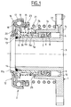
- the clutch operation is provided with a control device hydraulic comprising a fixed part 1 and a mobile part 2.
- the fixed part 1 is provided with a bore 3 and is, in general, mounted on a gearbox casing not shown.
- the fixed part 1 includes an inner tubular portion la, an outer tubular portion 1b and an lc sole.
- the fixed part 1 also includes a chamber annular 4 intended to receive a hydraulic fluid introduced by a orifice 5 and defined between the interior wall 9 formed by the portion inner tubular la, the outer wall 10 formed by the portion outer tubular 1b, the sole 1c and a piston 6.
- the movable part 2 comprises an annular piston 6 fully housed in annular chamber 4 and capable of movement axially under the pressure of hydraulic fluid applied to it.
- the piston 6 is provided with a first seal 7 in contact with the inner wall 9 of the annular chamber 4 and a second seal seal 8 in contact with the outer wall 10 of the chamber annular 4.
- the movable part 2 comprises an operating element 11 capable of transmitting the axial movement of the piston 6 to the bearing of stop 12.
- the operating element 11 can slide on the portion inner tubular la.
- the axial movement of the operating element 11 towards the outside of the fixed part 1 is limited by an elastic ring holding 13 disposed in an annular groove 14 of the portion inner tubular 1a and projecting from the wall interior 9.
- Thrust bearing 12 includes an inner ring not rotating 15, a rotating outer ring 16, a row rolling elements 17 in the form of balls, a holding cage 18 rolling elements 17 and a seal 19 secured to the outer ring 16 and in friction contact with the ring inner 15.
- the inner ring 15 is in contact with a surface radial 1 la of the operating element 11 and is mounted thereon so as to be able to move radially with respect to said element of operating element 11.
- the operating element 11 also includes a free end 11b supporting an elastic washer 20 which comes in bearing axially against the inner ring 15 which is thus rendered axially integral with the operating element 11.
- the radial clearance provided between the inner ring 15 and the operating element 11 allows a thrust bearing self-centering 12 relative to the element operation 11 and the fixed part 1.
- the outer ring 16 of the thrust bearing 12 is provided to be in contact with an element of the clutch diaphragm 29 (figure 2).
- the hydraulic clutch operating device includes a spring 21 for axial prestressing of the bearing 12 against the elements of the clutch diaphragm 29.
- the spring 21 is supported at its fixed end on a radial surface 22 of the fixed part 1.
- the mobile end of the spring 21 bears against the connecting piece 23 capable of radially holding the spring 21.
- the connecting piece 23 bears against the inner ring 15 and is axially and radially integral with the latter.
- the clutch operating device includes a seal seal 24 disposed radially between the outer wall 10 of the annular chamber 4 and the outer surface 11c of the element operation 11.
- the seal 24, of L-shaped section comprises a axial part 24a whose external surface 24b is in contact with the outer wall 10 and a radial part 24c projecting radially towards the interior with respect to the axial part 24a and in contact with the outer surface 11c of the operating element 11.
- the outer tubular portion 1b is provided, near the outer wall 10 of the chamber 4 of a chamfer 25 intended for facilitate fitting of the gasket 24.
- the fitting is also facilitated by the fact that the axial part 24a of the seal seal 24 has a smaller radial thickness than the radial part 24c and is therefore relatively flexible radially.
- the seal 24, once fitted on the outer wall 10, remains substantially stationary relative to the fixed part 1 and can just move from a few millimeters over the life of the device clutch operation towards the interior of the chamber 4.
- the seal between the fixed part 1 and the seal 24 is thus guarantee.
- the radial portion 24c of the seal 24 in contact with friction with the outer surface 11c of the operating element It also guarantees tightness.
- the operating element 11 is provided on its surface exterior 11c of a plurality of axial ribs 26 regularly distributed around the circumference of the operating element 11 in the purpose of increasing the rigidity of it and allowing to reduce its thickness. Reducing the thickness of the operating element 11 allows to radially accommodate the seal 24 between said element operating 11 and the outer wall 10. As can be seen particularly in FIGS. 4 and 5, the radial part 24c of the seal seal 24 is in shape with the outside surface 11c provided with ribs 26.
- An annular spring 27 is arranged around the ribs 26 of the operating element 11 and bears on a radial surface 11d of the operating element 11. The spring 27 exerts an axial force permanent towards the interior of chamber 4, on the organ seal 24 and prevents it from coming out of chamber 4.
- the ribs 26 of the operating element 11 are provided a radial shoulder 28 capable of coming into contact with the seal seal 24 and move it relative to the fixed part 1 towards the interior of the annular chamber 4.
- the shoulder 28 causes the fitting of the joint sealing 24 in the outer wall of chamber 4 up to a predetermined position illustrated in FIG. 2.
- the chamber 4 contains a small amount of hydraulic fluid.
- the piston 6 has entered chamber 4 until it is close to the sole 1c of the fixed part 1.
- the operating element 11 is also in retracted position which causes displacement of the seal 24 relative to the fixed part 1 under the effect of the shoulder 28.
- the axial position of the shoulder 28 is provided so that the axial part 24a of the seal partially fits over the wall outside 10.
- the spring 27 is put in compression and continues to exert an axial thrust on the seal.
- the spring will be calibrated so that the axial force exerted by said spring cannot move the sealing member 24 axially inside chamber 4, the tightening of said seal 24 in the outer wall of the chamber 4 opposing the penetration of the seal 24 under the action of spring 27.
- the disengaged position is illustrated in Figure 3.
- the chamber 4 has been filled with pressurized hydraulic fluid which repels the piston 6 towards the clutch diaphragm 29.
- the assembly of the movable part 2 is thus moved in this direction.
- Springs 21 and 27 relax.
- the seal 24 remains stationary by relative to the fixed part 1.
- the device can accommodate a slight axial displacement of the seal 24 in the direction of movement of the movable part 2, the seal 24 remaining in permanently in contact with the fixed part 1, thanks to the thrust exerted by spring 27.
- Figures 4 and 5 illustrate more particularly the shape match between the seal 24 and the element of operation 11.
- the radial portion 24c of the seal 24 is provided with radial slots 30 of shape corresponding to the ribs 26 of the operating element 11. The seal between the operation 11 and the seal 24 is thus ensured.
- the polluting particles cannot therefore penetrate either through the outer surface 24b of the seal 24 nor by the bore of said seal 24 which rubs against the operating element 11 because the axial width of the seal 24 constitutes an effective barrier containing the impurities at a sufficient axial distance from the piston 6.
- the axial position of the diaphragm 29 does not undergo variation over time for a given state, engaged or disengaged.
- the axial fitting position of the seal 24 will not vary so no. Otherwise, the wear of the clutch will have the effect of to offset the fingers of the diaphragm 29 axially towards the stop 12 for a given state, engaged or disengaged. Element shoulder 28 operating pressure 11 will therefore gradually push the seal 24 towards the interior of chamber 4 as the wear of the clutch. The tightness is thus reinforced.
- the seal 24 In the case of a variant where the operating element 11 is without shoulder, the seal 24 always remains in a identical axial position with respect to the entrance to chamber 4 which whether the wear of the clutch and the state, engaged or disengaged, of the mechanism. The seal 24 is first simply pushed axially by the spring 27 against the entry of the outer wall 10 of chamber 4 and thus ensures its closure.
- FIGS. 6 to 8 The embodiment illustrated in FIGS. 6 to 8 is similar to that of the previous figures except that the surface outer 11c of the operating element 11 is cylindrical and devoid of ribs. However, the shoulder 28 is retained.
- the bore 11e of the operating element 11 is provided with a plurality axial ribs 31 intended to maintain its rigidity and strength to the operating element without increasing its mass.
- the surface cylindrical outer 11c of the operating element 11 is provided, in the immediate vicinity of the piston 6, of a plurality of protrusions radial 32 capable of ensuring the axial retention of the seal 24 relative to the operating element 11 in order to constitute a easy-to-handle, removable assembly including seal 24, the spring 27 and the operating element 11.
- the seal 24 is of rectangular section and is provided on its outer surface 24b with three annular beads 33 in order to reduce the friction surfaces with the outer wall 10 and strengthen the seal by a chicane effect.
- the axial length of seal 24 has been increased and is slightly greater than the stroke of the movable part 2 relative to the fixed part 1 for prevent polluting particles deposited on the surface outside 11c when the device is in the disengaged position manage to enter room 4 during the movement of the game mobile 2 towards the engaged position, if said particles remained integral with said outer surface.
- the seal sealing 124 is U-shaped section with axial branches.
- Branch internal 134 is provided with a bore 134a in frictional contact on the cylindrical outer surface 111c of the operating element 111.
- the outer branch 135 is provided on its outer surface 124b three annular beads 133.
- the internal 134 and external branches 135 are connected by a connecting portion 136 on the side of the shoulder 128, opposite chamber 104.
- the seal 124 is partially fitted on the outer wall 110.
- the free end of the outer branch 135 is relatively flexible radially which facilitates fitting. Likewise, the flexibility of the internal branch 134 tends to reduce friction on the operating element 111.
- the shoulder 228 of the operating element 211 is provided, radially close to the external surface 211c, of a recess 237 in which the polluting particles can remain without the risk of being entrained inside the chamber 204.
- the seal 224 is also with a U-section but with branches of uneven thickness and arranged in the opposite direction to that of figure 9.
- the branch outer 235 is thick to receive the thrust of the spring 227 and be firmly fitted on the outer wall 210.
- the branch interior 234 is relatively thin, particularly at its end free so as to form a flexible scraping lip which will tend to accumulate polluting particles and other impurities in the hollow 237.
- the connecting portion 236 is disposed on the side of the chamber 204.
- an operating device is obtained very compact and economical manufacturing clutch. Friction seal on the operating element prevents intrusion impurities near the piston and in the chamber of the fixed part. This reduces the risk of harmful hydraulic fluid leaking the clutch works properly.
Landscapes
- Engineering & Computer Science (AREA)
- General Engineering & Computer Science (AREA)
- Mechanical Engineering (AREA)
- Hydraulic Clutches, Magnetic Clutches, Fluid Clutches, And Fluid Joints (AREA)
Applications Claiming Priority (2)
| Application Number | Priority Date | Filing Date | Title |
|---|---|---|---|
| FR9615937A FR2757589B1 (fr) | 1996-12-24 | 1996-12-24 | Dispositif de manoeuvre d'embrayage a commande hydraulique |
| FR9615937 | 1996-12-24 |
Publications (2)
| Publication Number | Publication Date |
|---|---|
| EP0851137A1 true EP0851137A1 (de) | 1998-07-01 |
| EP0851137B1 EP0851137B1 (de) | 2002-07-17 |
Family
ID=9499073
Family Applications (1)
| Application Number | Title | Priority Date | Filing Date |
|---|---|---|---|
| EP97403060A Expired - Lifetime EP0851137B1 (de) | 1996-12-24 | 1997-12-16 | Hydraulische Kupplungsbetätigungsvorrichtung |
Country Status (3)
| Country | Link |
|---|---|
| EP (1) | EP0851137B1 (de) |
| DE (1) | DE69714000T2 (de) |
| FR (1) | FR2757589B1 (de) |
Families Citing this family (2)
| Publication number | Priority date | Publication date | Assignee | Title |
|---|---|---|---|---|
| DE10349171A1 (de) * | 2003-10-22 | 2005-05-19 | Zf Friedrichshafen Ag | Betätigungseinrichtung für eine Reibungskupplung |
| JP6373264B2 (ja) * | 2012-07-17 | 2018-08-15 | シェフラー テクノロジーズ アー・ゲー ウント コー. カー・ゲーSchaeffler Technologies AG & Co. KG | 特に自動車におけるクラッチ操作システムに用いられるピストン・シリンダアッセンブリ |
Citations (8)
| Publication number | Priority date | Publication date | Assignee | Title |
|---|---|---|---|---|
| DE3504086A1 (de) * | 1985-02-07 | 1986-08-07 | Fichtel & Sachs Ag, 8720 Schweinfurt | Doppelnehmerzylinder mit zwei ausruecklagern zur betaetigung von schlepper-doppelkupplungen |
| US4995492A (en) * | 1989-10-10 | 1991-02-26 | Federal-Mogul Corporation | Reusable position retaining strap for clutch release mechanism |
| FR2651846A1 (fr) * | 1989-09-13 | 1991-03-15 | Automotive Prod France | Mecanisme de debrayage. |
| GB2259555A (en) * | 1991-09-13 | 1993-03-17 | Fichtel & Sachs Ag | Fluid-actuable releaser for a friction clutch |
| DE4427942A1 (de) * | 1993-09-08 | 1995-03-09 | Schaeffler Waelzlager Kg | Ausrückvorrichtung für eine Reibungskupplung |
| GB2287295A (en) * | 1994-03-09 | 1995-09-13 | Fichtel & Sachs Ag | An adjustable clutch actuator with a restraining device that allows for clutch wear |
| DE4412917A1 (de) * | 1994-04-15 | 1995-10-19 | Schaeffler Waelzlager Kg | Hydraulisch betätigbare Vorrichtung zum Ausrücken einer Schalttrennkupplung eines Kraftfahrzeugs |
| WO1996024782A1 (fr) | 1995-02-09 | 1996-08-15 | Valeo | Butee de debrayage a commande hydraulique pour un embrayage a diaphragme de vehicucle automobile |
-
1996
- 1996-12-24 FR FR9615937A patent/FR2757589B1/fr not_active Expired - Fee Related
-
1997
- 1997-12-16 EP EP97403060A patent/EP0851137B1/de not_active Expired - Lifetime
- 1997-12-16 DE DE69714000T patent/DE69714000T2/de not_active Expired - Fee Related
Patent Citations (8)
| Publication number | Priority date | Publication date | Assignee | Title |
|---|---|---|---|---|
| DE3504086A1 (de) * | 1985-02-07 | 1986-08-07 | Fichtel & Sachs Ag, 8720 Schweinfurt | Doppelnehmerzylinder mit zwei ausruecklagern zur betaetigung von schlepper-doppelkupplungen |
| FR2651846A1 (fr) * | 1989-09-13 | 1991-03-15 | Automotive Prod France | Mecanisme de debrayage. |
| US4995492A (en) * | 1989-10-10 | 1991-02-26 | Federal-Mogul Corporation | Reusable position retaining strap for clutch release mechanism |
| GB2259555A (en) * | 1991-09-13 | 1993-03-17 | Fichtel & Sachs Ag | Fluid-actuable releaser for a friction clutch |
| DE4427942A1 (de) * | 1993-09-08 | 1995-03-09 | Schaeffler Waelzlager Kg | Ausrückvorrichtung für eine Reibungskupplung |
| GB2287295A (en) * | 1994-03-09 | 1995-09-13 | Fichtel & Sachs Ag | An adjustable clutch actuator with a restraining device that allows for clutch wear |
| DE4412917A1 (de) * | 1994-04-15 | 1995-10-19 | Schaeffler Waelzlager Kg | Hydraulisch betätigbare Vorrichtung zum Ausrücken einer Schalttrennkupplung eines Kraftfahrzeugs |
| WO1996024782A1 (fr) | 1995-02-09 | 1996-08-15 | Valeo | Butee de debrayage a commande hydraulique pour un embrayage a diaphragme de vehicucle automobile |
Also Published As
| Publication number | Publication date |
|---|---|
| DE69714000D1 (de) | 2002-08-22 |
| EP0851137B1 (de) | 2002-07-17 |
| FR2757589B1 (fr) | 1999-01-22 |
| FR2757589A1 (fr) | 1998-06-26 |
| DE69714000T2 (de) | 2003-04-10 |
Similar Documents
| Publication | Publication Date | Title |
|---|---|---|
| EP0541472B1 (de) | Verriegelte Verbindung für Rohrleitungen | |
| EP0755488B1 (de) | Hydraulisch betätigtes ausrücklager für kraftfahrzeugkupplung mit membranfeder | |
| FR2512901A1 (fr) | Dispositif de debrayage a commande par fluide sous pression pour embrayages et, en particulier, pour embrayages de vehicule automobile | |
| FR2686659A1 (fr) | Emetteur hydraulique a reservoir integre et etanche. | |
| FR2819864A1 (fr) | Dispositif de butee de debrayage autocentreuse | |
| FR2934342A3 (fr) | Dispositif de commande hydraulique d'embrayage et embrayage correspondant. | |
| EP0538349A1 (de) | Auftragsvorrichtung für mehr oder weniger dickflüssige produkte. | |
| FR2474640A1 (fr) | Raccord rapide anti-fuite, notamment pour tuyauteries de transport de fluides hydrauliques | |
| FR2730532A1 (fr) | Butee de debrayage a commande hydraulique pour embrayage a diaphragme, notamment pour vehicule automobile comportant un manchon de guidage | |
| EP1463674B1 (de) | Fluidproduktabgabeventil und dieses umfassende fluidproduktabgabevorrichtung | |
| FR2688560A1 (fr) | Butee d'embrayage a commande hydraulique. | |
| FR2779489A1 (fr) | Dispositif de commande hydraulique de freinage ou d'un embrayage, notamment pour vehicule automobile | |
| EP0859161B1 (de) | Kupplungsbetätigungsvorrichtung mit einem selbsteinstellenden elastischen Element | |
| FR2861598A1 (fr) | Dispositif d'injection securise pour une seringue | |
| EP0851137B1 (de) | Hydraulische Kupplungsbetätigungsvorrichtung | |
| FR2953568A1 (fr) | Pompe a piston comportant un organe d'obturation au niveau de la soupape d'entree | |
| FR2938038A1 (fr) | Element d'etancheite sans zone de retention et dispositif de raccordement comportant un tel element d'etancheite | |
| FR2886696A1 (fr) | Dispositif d'accouplement d'une pompe a vide avec un arbre a cames comprenant des moyens d'alimentation en fluide lubrifiant | |
| FR2812923A1 (fr) | Dispositif d'accouplement d'un levier au piston d'un cylindre de commande | |
| EP1155255A1 (de) | Verbindungsvorrichtung für den anschluss einer leitung an ein element | |
| EP0010202A1 (de) | Unterdruckmembranvorrichtung für automatische Getriebe | |
| FR2739668A1 (fr) | Dispositif perfectionne d'obturation a guide centreur lubrifie pour tube d'amortisseur hydraulique pressurise | |
| FR2745619A1 (fr) | Dispositif de debrayage a commande hydraulique pour embrayage, notamment pour vehicule automobile | |
| FR2779496A1 (fr) | Dispositif de commande hydraulique d'un embrayage, notamment pour vehicule automobile | |
| FR2785648A1 (fr) | Verin d'embrayage pour une manoeuvre hydraulique d'embrayage |
Legal Events
| Date | Code | Title | Description |
|---|---|---|---|
| PUAI | Public reference made under article 153(3) epc to a published international application that has entered the european phase |
Free format text: ORIGINAL CODE: 0009012 |
|
| AK | Designated contracting states |
Kind code of ref document: A1 Designated state(s): DE FR GB IT |
|
| AX | Request for extension of the european patent |
Free format text: AL;LT;LV;MK;RO;SI |
|
| 17P | Request for examination filed |
Effective date: 19980629 |
|
| AKX | Designation fees paid |
Free format text: DE FR GB IT |
|
| RBV | Designated contracting states (corrected) |
Designated state(s): DE FR GB IT |
|
| 17Q | First examination report despatched |
Effective date: 20010215 |
|
| GRAG | Despatch of communication of intention to grant |
Free format text: ORIGINAL CODE: EPIDOS AGRA |
|
| GRAG | Despatch of communication of intention to grant |
Free format text: ORIGINAL CODE: EPIDOS AGRA |
|
| GRAG | Despatch of communication of intention to grant |
Free format text: ORIGINAL CODE: EPIDOS AGRA |
|
| GRAH | Despatch of communication of intention to grant a patent |
Free format text: ORIGINAL CODE: EPIDOS IGRA |
|
| GRAH | Despatch of communication of intention to grant a patent |
Free format text: ORIGINAL CODE: EPIDOS IGRA |
|
| GRAA | (expected) grant |
Free format text: ORIGINAL CODE: 0009210 |
|
| AK | Designated contracting states |
Kind code of ref document: B1 Designated state(s): DE FR GB IT |
|
| REG | Reference to a national code |
Ref country code: GB Ref legal event code: FG4D Free format text: NOT ENGLISH |
|
| GBT | Gb: translation of ep patent filed (gb section 77(6)(a)/1977) |
Effective date: 20020717 |
|
| REF | Corresponds to: |
Ref document number: 69714000 Country of ref document: DE Date of ref document: 20020822 |
|
| PLBE | No opposition filed within time limit |
Free format text: ORIGINAL CODE: 0009261 |
|
| STAA | Information on the status of an ep patent application or granted ep patent |
Free format text: STATUS: NO OPPOSITION FILED WITHIN TIME LIMIT |
|
| 26N | No opposition filed |
Effective date: 20030422 |
|
| PGFP | Annual fee paid to national office [announced via postgrant information from national office to epo] |
Ref country code: GB Payment date: 20051207 Year of fee payment: 9 |
|
| PGFP | Annual fee paid to national office [announced via postgrant information from national office to epo] |
Ref country code: FR Payment date: 20051216 Year of fee payment: 9 |
|
| PGFP | Annual fee paid to national office [announced via postgrant information from national office to epo] |
Ref country code: DE Payment date: 20060131 Year of fee payment: 9 |
|
| PG25 | Lapsed in a contracting state [announced via postgrant information from national office to epo] |
Ref country code: DE Free format text: LAPSE BECAUSE OF NON-PAYMENT OF DUE FEES Effective date: 20070703 |
|
| GBPC | Gb: european patent ceased through non-payment of renewal fee |
Effective date: 20061216 |
|
| REG | Reference to a national code |
Ref country code: FR Ref legal event code: ST Effective date: 20070831 |
|
| PG25 | Lapsed in a contracting state [announced via postgrant information from national office to epo] |
Ref country code: GB Free format text: LAPSE BECAUSE OF NON-PAYMENT OF DUE FEES Effective date: 20061216 |
|
| PG25 | Lapsed in a contracting state [announced via postgrant information from national office to epo] |
Ref country code: FR Free format text: LAPSE BECAUSE OF NON-PAYMENT OF DUE FEES Effective date: 20070102 |
|
| PGFP | Annual fee paid to national office [announced via postgrant information from national office to epo] |
Ref country code: IT Payment date: 20101227 Year of fee payment: 14 |
|
| PG25 | Lapsed in a contracting state [announced via postgrant information from national office to epo] |
Ref country code: IT Free format text: LAPSE BECAUSE OF NON-PAYMENT OF DUE FEES Effective date: 20121216 |