Technical Field
This invention relates to method and system
for the fluid transfer of fluid, such as paint, by a
fluid transfer device, such as a robot, and a non-contact
sensor for use with the method and system.
Background Art
In production paint operations, painters
change the color of the sprayed paint by disconnecting
their spray guns from one paint supply line, paint drop,
and connecting it to another paint drop of a different
color. The old paint color is purged by discharging a
small amount of the new color through the spray gun.
In contrast to manual painting, automated
painting machines require the addition of automatic
color changers. These devices use valves, manifolds,
and occasionally long tubes to connect different color
paints to the spray gun, purge the lines, valves,
manifolds, and the spray gun with solvent, and refill
with a new color paint. The long tubes cause considerable
waste of valuable paint material and the use of
much solvent to purge and clean the lines during color
changes. Environmental concerns have been raised about
the disposal of such materials and a more economical way
for changing paint color has been eagerly sought.
One option for addressing environmental
concerns has been the charging of the painting material
with a high voltage electrostatic charge, exceeding 100
KV, which helps improve its coating efficiency and the
economics of painting. Solvent based paints have been
successfully sprayed with electrostatic charge by virtue
of their natural insulating properties.
Another desirable option for addressing the
environmental concerns has been the use of water based
paints which pose much less threat to the environment
than solvent based paints. Unfortunately, such paints
are conductive of electricity and can be sprayed electrostatically
only from insulated canisters, disconnected
from the paint supply lines. The filling, purging,
cleaning, and refilling of such canisters with different
paint colors has been a challenge looking eagerly for
economic solutions, particularly for high volume production
operations requiring frequent color changes.
U.S. Patent No. 4,313,475 to Wiggens addresses
these challenges by means of a system of supply lines,
color changers, valving arrangements, and air entrapping
containers to fill the containers from the supply line,
when the electrostatic charge is turned off. Valves are
actuated to cause a discontinuity in the supply line,
termed voltage block, that isolates it from the charged
paint in the canister. Air entrapped in the container
and pressurized by the filling of the canister causes
the paint to flow from the canister to the spray equipment
while the paint is electrostatically charged.
U.S. Patent Nos. 4,771,729 to Planert et al;
4,932,589 to Diana; 4,879,137 to Behr et al; and
4,921,169 to Tilly all disclose various methods and
apparatus for electrostatically coating a conductive
material utilizing an electrical isolation mechanism,
including a reservoir into which a metered volume of
paint to be sprayed is introduced.
With the advent of robots, production spray
painting became more efficient and attained higher
quality. Color changing for robots followed the lead of
automatic spray machines by using automatic color
changers. However, the mobility of the robot also
caused the spray lines to become longer and require more
solvents to purge and clean. Electrostatics also cause
damage to the long flexible supply lines as they get in
contact with grounded surfaces, and eventually fail. To
continue the use of electrostatics, especially with
water based paints, a better method is sought for paint
delivery, color changing, and electrostatic isolation,
for robotic paint spray equipment.
The current approach is to connect a spray
applicator by means of fluid lines to an outlet port of
a paint color changer. The color changers is piped to
a series of paint outlets (color drops). The color
changer controls the flow of paint, air and cleaning
solvents to the applicator by means of a valving arrangement.
Valves are selectively opened or closed to
pass the appropriate paint color to the applicator, to
purge the fluid lines with air or solvents, and to clean
the lines between.
Most methods of delivering paint by robots to
a workpiece keep the robot connected to the supply lines
by means of hoses. The length of the hoses causes paint
to be wasted during color change, waste of robot time
when idled for purging and color change, and restricts
robot mobility.
For electrostatic painting with conductive
paints, such as water based paints, the charging of the
paint causes the high voltage charge to be communicated
to the rest of the paint supply system through the paint
lines, hence impeding the use of such paints despite
their environmental advantages.
Most current methods for painting with robots
require the use of automatic color changers with a
multiplicity of valves and control solenoids to connect
the appropriate color to the spray gun of the robot and
to provide sequenced operations for color changing and
line cleaning. This is not always a necessity and adds
expense and complexity to the painting process.
In contrast with the above, manual painting
requires no color changers as the person has the ability
to connect his spray gun to the source of the desired
color directly and disconnect it when he is finished
using that particular color. Cleaning is also limited
to the spray nozzle since the paint delivery lines need
not be cleaned as they do not pass different color
paint, hence manual painting uses little cleaning
solvents. Furthermore, less time is spent to switch
from one color to another, without paint line cleaning,
allowing more time for productive painting. However,
manual painting is known to be deficient in quality.
U.S. Patent No. 4,785,760 to Tholome discloses
a sprayer installation including a robot, a sprayer
carried by the robot and a storage tank for a fluid,
such as paint to be sprayed, also carried by the robot.
The mobility of the robot simplifies its
operation and eliminates the need for automatic color
change equipment. Mobility of the robot is also used to
eliminate the need for special insulating provisions to
isolate the spray equipment from the paint supply lines.
The robot mimics manual painting operations rather than
automatic machine operations, hence, requiring no
automatic color changers, and no special voltage blocks
for periods of electrostatic spraying.
U.S. Patent Nos. 3,674,207 to Carbonetti, Jr.
et al; 4,944,459 to Watanabe et al; and 5,029,755 to
Schmidt et al all disclose the use of a robot or manipulator
which is utilized with other apparatus to change
paint color.
Summary Of The Invention
An object of the present invention is to
provide a practical method and system for color changing
in production painting operations using a transfer
device, hence eliminating the need for supplemental
automatic color changers without straining the transfer
device.
Another object of the invention is to provide
a system and method for docking a container carried by
a transfer device with a pressurized source of fluid for
filling the container with the fluid without straining
the transfer device.
Still another object is to provide a method
and system for cleaning a painting container carried by
a transfer device between container fillings without
loss of productive time.
Still further, an object of the invention is
to provide a method and system for cleaning a robotic
canister that uses less solvents and is more friendly to
the environment.
Another object of the invention is to provide
a non-contact sensor for metering the flow of fluid in
a container.
Still another object is to provide an improved
method and system for robotic painting wherein the robot
carries its desired quantity of paint in a reservoir to
the painted object and cleans the reservoir before
filling it with a new color paint. This eliminates the
long and cumbersome paint lines connecting the robot to
the paint source lines, thus reducing paint waste and
the need for using environmentally hazardous solvents.
An object of the invention is to provide a
method and system for eliminating the need for isolating
electrostatically charged robotic paint process equipment
from paint supply lines, hence enabling the use of
environmentally desirable conductive, water-based, paint
materials.
Finally, a still further object of the invention
is to provide a robotized paint spraying method and
system complete with a robot, paint spraying means,
paint reservoir, docking means for the reservoir with a
paint drop, means for cleaning the paint passages
between canister fillings as necessary for color changing,
means to maintain the filling interfaces clean
during actual painting operations, and control means for
programmed control of the robot, and the canister
docking, filling and cleaning sequences.
In carrying out the above objects and other
objects of the present invention, a method for transferring
fluid from a pressurized source of fluid is provided.
The method includes the steps of providing the
pressurized source of fluid with an outlet valve and
providing a transfer device with a fluid reservoir
having an inlet valve and a delivery device for the
fluid. The method also includes the steps of moving the
transfer device with the reservoir to a docking position
so that the inlet valve of the reservoir is located
immediately adjacent the outlet valve of the pressurized
source of fluid, sealingly mating the inlet valve with
the outlet valve and opening the inlet and outlet valves
to fluidly communicate a filling port of the reservoir
and a fluid outlet of the pressurized source of fluid.
Finally, the method includes the steps of filling the
reservoir with a predetermined amount of fluid from the
pressurized source of fluid, closing the inlet and
outlet valves, moving the transfer device with the
filled reservoir to a fluid delivery position and
fluidly communicating the fluid from the reservoir to
the delivery device.
Preferably, the inlet and outlet valves are
opened substantially simultaneously and the inlet and
outlet valves are closed substantially simultaneously.
Also, preferably, the method further includes
the step of providing actuating means movable between a
home position, a sealing position, and an actuating
position wherein the Step of opening includes the step
of moving the actuating means from its home position to
the sealing position to apply a sealing force for mating
the inlet and outlet valves and then to its actuating
position to open the inlet and outlet valves.
Preferably, the inlet valve is sealingly mated
with the outlet valve during the steps of opening,
filling and closing.
Also, preferably, the method further includes
the step of sealing protecting the filling port from
contamination at least during the step of moving the
transfer device to the fluid delivery position.
A system is also provided for carrying out
each of the above steps.
Further in carrying out the above objects and
other objects of the above invention, a non-contact
sensor for sensing the linear position of a body which
moves linearly in an environment is provided. The
sensor includes an assembly having means for defining a
cavity insulated from the environment and generating
means for generating a magnetic field within the cavity.
The generating means is adapted to be coupled to the
body to move linearly therewith. The assembly includes
a sensor element disposed within the cavity and a
ferromagnetic device supported for linear movement
within the cavity to move in response to movement of the
generating means and its magnetic field along the sensor
element. The sensor element has a property which is a
function of the position of the device along the sensor
element within the cavity. The sensor is adapted to
provide a signal representative of the property of the
sensor element whereby the position of the device along
the sensor element in the cavity is indicated.
Preferably, the generating means includes a
magnet.
The above objects and other objects, features,
and advantages of the present invention are readily
apparent from the following detailed description of the
best mode for carrying out the invention when taken in
connection with the accompanying drawings.
Brief Description Of The Drawings
FIGURE 1 is a schematic side elevational view,
partially broken away and in cross-section, illustrating
the method and system of the present invention;
FIGURE 2 is a cross-sectional view of a
canister and actuating cylinder illustrating passages
feeding into a manifold for spray gun control;
FIGURE 3 is a side elevational view partially
broken away of a paint drop cluster wherein different
color drops share a single casing;
FIGURES 4-7 are enlarged side elevational
views, partially broken away and in cross-section
illustrating the details of the mechanism for filing the
canister and the procedure for doing so;
FIGURE 8 is similar to Figures 4-7 but illustrate
the step of maintaining the contents of the
canister in a sealed condition;
FIGURE 9 is a view similar to Figure 1 but
illustrating another embodiment of the invention;
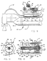
FIGURE 10 is an enlarged side elevational
view, partially broken away and in cross-section,
illustrating the canister of Figure 1 with a non-contact
sensor; and
FIGURE 11 is an end sectional view of the
canister of Figure 10.
Best Mode For Carrying Out The Invention
General Description
Referring to Figure 1, in the method and
system of the present invention, a transfer device such
as a robot, generally indicated at 10, carries a reservoir
or canister, generally indicated at 12, and uses
the fluid contained therein to spray an object by way of
a spraying device, such as a spray gun 14. The canister
12 is filled with the fluid such as a paint of a desired
color and is fixedly attached to a robot part such as a
robot wrist 16 or a robot arm part 11' as illustrated in
Figure 9.
When the canister 12 is emptied, the robot 10
"docks" at a paint supply station, connects the canister
12 to the source of paint by means of a check-valved
connection similar to that used with manual painting,
and allows the canister 12 to be refilled by the desired
paint. When the color is to be changed, the robot 10
initiates a sequence to clean the canister 12 before
refilling, and prepares it to accept a different color
paint without risk of contamination by residues remaining
from a previously used paint color.
In one embodiment, the cleaning sequence is
initiated internal to the robot 10, and the robot 10
connects to individual paint drops, each having a
different color paint, hence eliminating the need for
automatic color changers. This method requires that the
robot 10 either carries its own solvent and air cleaning
lines, or is programmed to go to docking locations of
solvent and air lines, preferably adjacent to the
docking locations of the paint supply lines.
In another embodiment, the robot 10 is connected
to a color changer and the sequence of cleaning
is initiated through the valves of the color changer.
While this approach has the expense of a color changer
associated with it, it may be applied to robots in
existing installations already having automatic color
changers as it relieves the robot 10 from carrying the
cleaning lines, and relieves its controller from the
task of programming several locations for filling from
different paint drop locations. The method and system
would still have the advantages of eliminating long
paint supply lines and its ability to accommodate
electrostatic water-based, as well as solvent-based,
paints without special insulating provisions for purging
and filling.
In support for the method and system of the
invention, a docking valve arrangement is provided to
enable the attachment of the canister 12 to the paint
drops which cleans the interfaces before connections are
made, and maintains a protective cover over the filling
interface during the spraying operation, hence avoiding
color contamination between canister fillings.
Furthermore, a non-contact sensor is described
to allow metering of the filling of the canister 12 in
order to use only the exact amount of paint as needed to
finish painting a known object.
An embodiment of the invention is also described
for an integral canister-robot system having
means for displacing paint, metering the amount of paint
used, cleaning the canister 12 and paint spray equipment,
and docking the canister 12 to a know paint supply
location.
Without lines connecting the paint reservoir
to the paint supply lines, the method and the system are
ideal for use with electrostatically charged and conductive
paint materials. It eliminates the need for
elaborate, complex, and expensive isolation methods,
known as voltage blocks, to keep the electrostatic
charge from leaking to the normally grounded paint
supply lines.
Detailed Description
With reference again to Figure 1, the canister
12 is mounted to a part of the robot 10, such as the
hollow wrist 16, and may be filled with fluid by docking
a check valve or valve assembly, generally indicated at
18, with a fluid supply outlet, such as a check valve or
paint drop, generally indicated at 20, and clamping them
together by means of an actuating cylinder, generally
indicated at 22, to effect fluid communication between
the paint drop 20 and the canister 12. The hollow wrist
16 may generally be of the type disclosed in U.S. Patent
No. 4,708,580 to Akeel.
The canister 12 consists of a cylinder 24
which encloses a piston 26 which has a scraper seal 28
attached to a front face of the piston 26 and which
slidably engages an internal cylindrical surface 30 of
the cylinder 24 to scrape paint off the surface 30.
Spaced bearing rings 32 circumferentially
mounted on the piston 26 provide side support for the
piston 28 against possible frictional moments resulting
from the movement of the scraper seal 28 inside the
cylinder 24.
A central post 34 is used to guide linear
movement of the piston 26 and for inclusion of a piston
position sensing device as described hereinbelow.
A cylinder liner 36 provides a favorable
sliding and scraping surface for the scraper seal 28.
The piston 26 may be propelled toward a port 38 in the
canister 12 by means of pressurized fluid, such as air,
introduced into a cavity 40 on one side of the piston 26
through a port 42 in a manifold 44 and a cylinder cap 46
of the canister 12. When a cavity or reservoir 48 of
the canister 12 is full of fluid, such as paint, the
fluid is propelled on the opposite side of the piston 26
to flow through the port 38 for productive use, such as
spray painting.
The check valve 18, as illustrated in detail
in Figure 4, includes a casing 50 and an end cap 52
which encloses a spring 54 which acts on a check valve
puppet 56 to close a port 58 in the casing 50 as best
shown in Figure 7. The check valve 18 mounts on cylinder
24 as shown in Figure 1, such that a port 60 in the
cylinder 24 and a port 62 in the casing 50 are in fluid
communication.
The actuating cylinder 22 has a cylinder body
64 closed at one end thereof by an end cap 66 and at its
other end by the sealed engagement of a plunger 68 and
a sealing means such as a circular seal 70. A piston 72
is sealingly mounted for sliding movement within the
cylinder body 64 by a seal 73. The piston 72 is connected
to a check valve puppet 74 to move linearly
through and is biased away from the plunger 68 by a
spring 76 to effect the closing of a port 78 in the
plunger 68 by the check valve puppet 74.
The seal 70 allows the piston 72 to be slidably
actuated by means of pressurized fluids introduced
into cylinder cavities 80 and 82 at ports 84 and 86,
respectively. The cylinder body 64 mounts on the
canister body or cylinder 24 such that the ports 84 and
86 are in fluid communication with fluid supply passages,
such as a passage 88 as shown in Figure 1. The
passage 88 is communicated to external control valves
(not shown), through ports such as a port 90 in the
manifold 44 and the end cap 46. Alternatively, the
ports 84 and 86 may be communicated to such external
control valves by means of hard or flexible tubing as
illustrated in Figure 9.
As shown in Figure 8, the cylinder 22 is
mounted in axial alignment with the check valve 18 such
that the extension of the plunger 68 causes the puppet
74 to engage the check valve puppet 56 in a mating
arrangement, the purpose of which is described below.
Referring to Figure 2, there is illustrated
control passages 91 in the cylinder 24 which feed into
a manifold 93 for spray gun control functions.
Referring to Figure 3, there is illustrated a
paint drop cluster, generally indicated at 19, having
different color drops 20, 20' etc. which share a single
casing.
As illustrated in Figure 4, the paint drop 20
has a casing 92 with supply and return ports 94 and 96,
respectively, and a cartridge 98 containing a check
valve puppet 100 with an end cap 102. A spring 104
keeps the check valve 20 closed as the spring 104 acting
on the end cap 102 forces the puppet 100 against a valve
seat 106 of the cartridge 98. A spring housing 108
keeps contaminants away from the check valve assembly.
Normally, fluids such as paint are continuously
circulated through the paint drop 20 as they enter
through the supply port 94 and exits through the return
port 96. Paint circulation keeps paint pigments from
forming sediments inside a paint drop cavity 110 within
the cartridge 98 and maintains paint color uniformity.
Canister Filling
The paint drop 20 is mounted to any fixed
structure by means of supports 118. The supports 118
are compliant to accommodate the lateral movement that
is necessary to assure a firm sealing engagement at the
interface between the paint drop 20 and the check valve
18.
To fill the canister 12 with paint from the
paint drop 20, the robot wrist 16 is moved to allow the
check valve 18 and the cylinder 22 to straddle the paint
drop 20 as shown in Figure 1. The wrist 16 is then
moved to engage the check valve 18 with the paint drop
20 in a butted arrangement as shown in Figure 5.
Conical engagement surfaces 112 and 114 help guide the
engagement. The cylinder 22 is then activated by
introducing pressurized air through the port 84 into the
cavity 80 to engage the plunger 68 with the spring
housing 108, as shown in Figure 6, and help secure the
sealing engagement of surfaces 112 and 114 by compressing
a seal 116 in the casing 50.
Further movement of the piston 72 compresses
the spring 76 and advances the valve puppet 74 against
the end cap 102 to compress the spring 104 and engage
the puppet 100 with the puppet 56 as both progressively
move in the same direction to open both check valves and
allow fluid communication between the port 58 and the
cavity 110, as shown in Figure 7. Paint is then allowed
to flow from the supply port 94 of the paint drop 20
through the ports 58, 62 and 60 into the canister cavity
48.
Normally, filing is initiated when the cavity
48 is at minimum volume. As paint flows into the
canister 12, it displaces the piston 26 to increase the
cavity 48 and reduce the cavity 48 until the desired
volume of paint has been introduced into the canister
12. The volume of paint may be metered by timing the
flow of paint into the cylinder, by monitoring the
displacement of the piston by means of linear potentiometers,
for example, or by any method of flow measurement
techniques.
When the desired quantity of paint is in the
canister 12, a programmable controller (not shown) shuts
off the pressurized fluid, or air, from the port 84 and
allows the spring 76 to expand thus retracting the
piston 72 and the check valve puppet 74 away from paint
drop 20. The spring 104 then expands and causes the
puppet 100 to retract and close the port 106, thus
shutting off the flow of paint into the valve 18 and the
canister 12. Simultaneously, the puppet 56 moves under
the action of its spring 54 to close the port 58, hence
trapping the paint inside the canister 12.
When air is introduced into the cylinder body
64 through the port 86, the piston 72 is moved into the
cavity 80 thus causing the plunger 68 to recede into the
cylinder body 64 thus freeing the engagement with the
paint drop 20. The robot 10 then moves away from the
paint drop 20 and air is introduced into the cylinder
body 40 at the port 84 to move the plunger 68 into
engagement with the check valve 18, hence protecting the
cleanliness of the port 58 from contamination and to
prepare the canister 12 for filling with the same or a
new color paint. The robot 10 then begins its painting
sequence, using the paint contained in the canister 12.
For refilling with the same paint, the sequence
described above is repeated at the same paint
drop 20.
For changing color, the canister 12 is first
cleaned before the sequence described above is repeated
at another color drop 20' of the new desired paint color
illustrated in Figure 3.
Canister Cleaning
Cleaning of the canister 12 is done while the
plunger 68 is in a sealed engagement with the valve
assembly 18 as shown in Figure 8. High pressure fluid,
such as air, is introduced at the port 84 to force the
puppet 74 to engage the puppet 56 and allow fluid
communication between the port 78 and the port 58.
Cleaning fluid, preferably shots of cleaning solvents
and air, is introduced through the port 86 to pass
through the cavity 82 and ports 78, 58, 62, and 60 into
the canister 12, and then through the port 38 to the
spray gun 14 or a dump valve (not shown), hence washing
away any paint residues that may cling to the surfaces
of the canister 12 and its contained parts. When
cleaning is finished, the canister 12 may be dried by
passing air only through the port 86. When cleaning and
drying is complete, the canister 12 is then ready for
storage or for filling with a new color.
By providing a dielectric insulator between
the canister 12 and the mounting robot part, the paint
can be charged with high voltage electrostatic charge
without causing the charge to leak to the grounded robot
parts. With no connection between the canister and the
paint drops, 20, 20', etc., after disengagement, the
system requires no elaborate or costly isolation by
voltage block arrangement as described in the prior art.
Referring to Figure 9, there is illustrated a
second embodiment of the method and system of the
present invention wherein parts which perform the same
or similar function to the parts of the first embodiment
have a prime designation. In Figure 9, a canister,
generally indicated at 12' is mounted on an arm 11' of
a robot, generally indicated at 10'. An external paint
house 13' provides paint to a spray gun 14'. External
gun control lines 90' and 42' provide control signals to
control the functioning of the canister 12'. Spray gun
control lines (not shown) internal to the robot arm 11'
and the wrist 16' provide control signals to the spray
gun 14'.
As in all robotic arrangements, the system is
usually controlled by a programmable controller which
can be programmed to introduce fluids through different
valves in a timed and desired sequence.
Non-Contact Position Sensor
In order to sense the linear position of the
piston 26 in the canister 12 without contacting with the
piston 26, a non-contact positioning sensor generally
indicated at 120 is provided as illustrated in Figures
9 and 10. The paint within the cavity 48 is electrostatically
charged at high voltage, typically 100KV. As
previously mentioned, the piston 26 is displaced by
pressurized paint entering the cavity 48 at the port 60
to be discharged to the spray device 14 through the port
38 by introducing pressurized air through the port 42
into the cavity 40 while port 60 is closed by a check
valve (not shown). The seal 28 cooperating with the
guide rings 32 help separate the paint and air chambers
48 and 40, respectively. A spacer 93 prevents the
piston 26 from engaging the end of the cylinder 24.
The sensor 120 monitors and controls the position
of the piston 26 as it travels inside the canister
12 to allow the metering of the amount of paint entering
into, or discharged from, the canister 12. Exposing
conventional sensors, such as potentiometers, encoders,
linear variable differential transformers (LVDT), or the
like to the paint is impractical. Hence, a non-contact
sensor that is isolated from the paint environment of
the piston 26 is a necessity. Sensors that track the
piston from outside the canister 12 are possible to
install, but when space is limited, an internal sensor
is required and should be insulated from the pain and
electrostatic environment.
As shown in Figure 10, the sensor 120 includes
the hollow, plastic central post 34 containing a sensor
element 124, a guide wire or element 126 and a tracer
element 128. The sensor element 124 may be of any
conventional type, such as a potentiometer resistive
element, a toothed encoder element, an optical or
magnetically encoded element or the like.
A mechanism for generating a magnetic field
such as a magnet 130 is secured to move with the piston
26 and is mounted such that it traps the tracer element
128 by its magnetic field. The tracer element 128 is
made of a ferromagnetic material so as to be responsive
to the magnetic field of the magnet 130, and is mounted
to slide along the guide element 126 while it engages
the sensor element 124 either by direct contact or
through electromagnetic or optical coupling.
Accordingly, when the piston 26 is displaced
inside the canister 12, the tracer element 128 is moved
along the guide element 126 in response to the movement
of the magnet 130 with the piston 26. The sensor
element 124 provides a signal that is indicative of the
position of the tracer 128, and hence of the piston 26.
The signal is then communicated to the outside of
canister 12 by terminals 132 and 134, for use by a
conventional control means or controller to regulate the
flow of the fluid into the canister 12 or the displacement
of the piston 26 pushing the fluid. The tracer
element 128 may be of the simple construction such as a
contact wiper when the sensor element 124 is a resistance
potentiometer.
The signal indicating the position of the
piston 26 may then be measured by several well known
methods. For example, when a voltage Vo is applied
between the terminals 132 and 134, a measurement of the
current flowing into the potentiometer 124 through the
guide wire 126 is a measure of piston position within
the canister 12.
When a voltage Vo' is applied between the two
end terminals 132 of the potentiometer 124, the voltage
between one of the two end terminals 132 and the terminal
134 is a measure of the position of the tracer, and
hence the piston 26.
If two equal resistances are connected to the
terminals 132, and a voltage Vo'' is applied between the
terminals 132, in a well known arrangement known as a
Wheatstone Bridge, the voltage between the terminal 134
and the junction of the resistances is a measure of the
position of the tracer 128.
These methods require that the tracer 128
makes electrical contact with the potentiometer or
sensor element 124 and that the guide element 126 is
also electrically conductive. A conductive lubricant
may be used at the bearing surface between the guide
element 126 and the tracer 128 to reduce friction. This
improves sensor responsiveness and resolution by preventing
restriction or tracer breakaway from the magnetic
field.
Summary
The new method and system uses a robotic
manipulator to carry a container that is piped to a
spray applicator, and connects it directly to paint
color outlets (paint drops) without the need for a color
changer. Accordingly, the robotic manipulator, through
its controls program, seeks the paint drop of the
desired color, connects the container for filling with
the desired paint color, and then activates the spray
applicator for productive paint spraying use. The
manipulator has access to sources of pressurized air for
paint delivery and line purging as well as sources for
cleaning fluids. Valving arrangements are provided on
the manipulator to control the flow of fluids according
to the desired sequences of painting or cleaning.
The method and system involves the mating of
two check valves in a sealed arrangement and the simultaneous
opening of the two valves to effect the flow of
fluid from the fluid source into the container. One of
the two valves opens inwardly into the container while
the other opens outwardly from the fluid outlet.
Springs keep the two valves normally closed until an
actuator is energized to push the spring loaded stem of
one valve against its spring, thus opening it and
simultaneously pushing the other valve also to open;
hence, allowing fluid communication between the container
and the fluid outlet.
The method and system allow the filling of
containers in a sealed environment, wherein the interfaces
are wiped clean by virtue of the tandem movement
of the two valves hence allowing no space to exist
between the valves at any instant during the opening or
closing operation, hence, minimizing loss of fluids and
the need for excessive cleaning effort of the interfaces.
The method and system also involve the use of
a protective interface to keep the filling port clean
from outside contamination, the use of the protective
interface to communicate cleaning fluids to the canister
without disengagement, and the use of the same protective
interface to secure positive engagement of the
filling port with the fluid outlet during subsequent
filling operations.
A non-contact sensor utilized in the system
and method is a linear transducer that senses the
position of a piston being displaced by the filling
fluid and the termination of filling when the piston
reaches a location indicating that the desired amount of
fluid has entered the container.
The non-contact sensor responds to the motion
of the piston by means of magnetic coupling wherein
there is no physical contact between the moving object
and any part of the sensor. By contrast, LVDT's sense
motion by magnetic coupling but require that the object
physically push one of the sensor elements relative to
the other.
The piston carries a magnetic field generating
mechanism such as a magnet which cooperates with a
responsive ferromagnetic tracer of the sensor. The
sensor element may be an electrically resistive potentiometer
cooperating with the conductive ferromagnetic
tracer.
The ferromagnetic tracer in the sensor is
preferably a bead made of a conductive ferromagnetic
material and is guided along the conductive guide wire
and forced to contact the sensor element by the magnetic
force. Since the guide wire or element is conductive,
it can communicate a signal of the sensor to a controller.
The sensor element is isolated electrostatically
and fluidly from the piston and its environment.
While the best mode for carrying out the
invention has been described in detail, those familiar
with the art to which this invention relates will
recognize various alternative designs and embodiments
for practicing the invention as defined by the following
claims.