EP0851119A2 - Hydraulikmotor mit radial angeordneten, rohrförmigen Antriebselementen - Google Patents
Hydraulikmotor mit radial angeordneten, rohrförmigen Antriebselementen Download PDFInfo
- Publication number
- EP0851119A2 EP0851119A2 EP97203800A EP97203800A EP0851119A2 EP 0851119 A2 EP0851119 A2 EP 0851119A2 EP 97203800 A EP97203800 A EP 97203800A EP 97203800 A EP97203800 A EP 97203800A EP 0851119 A2 EP0851119 A2 EP 0851119A2
- Authority
- EP
- European Patent Office
- Prior art keywords
- motor according
- axis
- cylinder
- retaining
- eccentric cam
- Prior art date
- Legal status (The legal status is an assumption and is not a legal conclusion. Google has not performed a legal analysis and makes no representation as to the accuracy of the status listed.)
- Granted
Links
Images

Classifications
-
- F—MECHANICAL ENGINEERING; LIGHTING; HEATING; WEAPONS; BLASTING
- F03—MACHINES OR ENGINES FOR LIQUIDS; WIND, SPRING, OR WEIGHT MOTORS; PRODUCING MECHANICAL POWER OR A REACTIVE PROPULSIVE THRUST, NOT OTHERWISE PROVIDED FOR
- F03C—POSITIVE-DISPLACEMENT ENGINES DRIVEN BY LIQUIDS
- F03C1/00—Reciprocating-piston liquid engines
- F03C1/02—Reciprocating-piston liquid engines with multiple-cylinders, characterised by the number or arrangement of cylinders
- F03C1/04—Reciprocating-piston liquid engines with multiple-cylinders, characterised by the number or arrangement of cylinders with cylinders in star or fan arrangement
- F03C1/0403—Details, component parts specially adapted of such engines
- F03C1/0406—Pistons
-
- F—MECHANICAL ENGINEERING; LIGHTING; HEATING; WEAPONS; BLASTING
- F03—MACHINES OR ENGINES FOR LIQUIDS; WIND, SPRING, OR WEIGHT MOTORS; PRODUCING MECHANICAL POWER OR A REACTIVE PROPULSIVE THRUST, NOT OTHERWISE PROVIDED FOR
- F03C—POSITIVE-DISPLACEMENT ENGINES DRIVEN BY LIQUIDS
- F03C1/00—Reciprocating-piston liquid engines
- F03C1/02—Reciprocating-piston liquid engines with multiple-cylinders, characterised by the number or arrangement of cylinders
- F03C1/06—Reciprocating-piston liquid engines with multiple-cylinders, characterised by the number or arrangement of cylinders with cylinder axes generally coaxial with, or parallel or inclined to, main shaft axis
- F03C1/0602—Component parts, details
- F03C1/0605—Adaptations of pistons
Definitions
- the present invention relates to a hydraulic motor with propulsion members retained against corresponding sliding-contact surfaces by resilient means located outside the said propulsion members and arranged between the latter and associated means for mechanically retaining them.
- Said propulsors may be arranged radially or inclined as described in a co-pending patent application in the name of the same Applicant.
- a resilient element such as a helical spring for example, arranged coaxially with respect to the propulsor and designed to push against corresponding internal shoulders of the cylinder and the piston so as to press said cylinder and piston against the associated abutment surfaces.
- the technical problem which is posed, therefore, is that of providing a hydraulic motor in which there are provided means for mechanically retaining each propulsion member against respective abutment and sliding-contact surfaces where a hydraulic seal against leakage of the thrusting fluid must be ensured.
- said mechanical-retaining means should comprise resilient means acting on the propulsion members with a thrust in a direction parallel to that of their longitudinal axis, which is independent of the working phase (compression/discharge) of the propulsion member itself.
- said resilient retaining means should be easy and economical to construct and install on motors of the known type and allow the motor to be used also as a pump.
- a hydraulic motor with propulsion members located between an eccentric cam associated with the drive shaft and a counter-element, said propulsion members consisting of two elements slidable telescopically with respect to one another in the longitudinal direction and having annular bearing edges kept pressed against corresponding sliding-contact surfaces of said eccentric cam and counter-element by means of associated resilient means, wherein said resilient means are arranged outside the said propulsion members and located between said annular edges and associated means for mechanically retaining them.
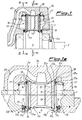
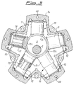
- the hydraulic motor according to the invention in the version with radial propulsors comprises a casing 1 which houses inside it the shaft 2 mounted on bearings 2a and carrying the eccentric cam 3 against which the propulsion members 10 act radially.
- Said propulsion members 10 in turn consist of a cylinder 11, one of the two end edges of which bears against the external surface 3a of the said eccentric cam 3, and a piston 12, slidable telescopically in the radial direction inside the cylinder 11 and having one of the two end edges in abutment against a spherical surface 1a formed inside covers 1b fastened to the casing 1 of the motor by means of suitable fixing means not shown.
- the bearing edge of said cylinder 11 and piston 12 against the respective sliding-contact surfaces 1a and 3a of the cover 1b and the eccentric cam 3 substantially consists of an annular edge 11a, 12a having a contact surface 11b,12b, parallel with the surface of the eccentric cam, and a tooth 11c,12c extending towards the outside and designed to engage with the radially retaining means described below.
- Said retaining means comprise essentially three elements both in the zone of contact between cylinder 11/eccentric cam 3 and in the zone of contact between piston 12/cover 1b.
- said retaining elements are composed of: a sliding piece 13 provided with a coaxial hole 13a having a diameter slightly greater than the external diameter of the cylinder 11 so as to allow the latter to pass through.
- Said sliding piece 13 has moreover at least one pair of edges 13c, which are opposite and parallel, having a substantially L-shaped section and extending along a substantially cylindrical profile, coaxial with the axis of the eccentric cam 3.
- the short arm 13d of each "L" has an upper surface 13f designed to form an engaging seat for a ring 15 having its centre on the axis of the drive shaft 2 and arranged around each edge 13c of all the sliding pieces 13 retaining each cylinder 11.
- a resilient element is arranged them, said element in the example consisting of a wave spring 16 designed to impart a radial force of relative contact between the surfaces making sliding contact, said force being constant and independent of the working phases of the propulsion member 10.
- the retaining elements again consist of a ring 17 which is centred on the radial axis and fastened to the cover 1b of the motor and which has a concave spherical surface 17a designed to press on a corresponding convex spherical surface 18a of a sliding piece 18 in turn acting in the radial direction against an annular edge 12a of the piston 12.
- a wave spring 16 is arranged between sliding piece 18 and annular edge 12a in order to ensure constant adhesion of the sliding-contact surfaces during the various working phases of the propulsion member 10.
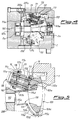
- the hydraulic motor is of the type with propulsors 110 which are inclined, i.e. having their longitudinal axis inclined both with respect to the drive shaft 102 and with respect to the longitudinal axis of the other propulsors, the latter are arranged between a disc 200 keyed onto the shaft 102 and an eccentric cover-piece 103 which is substantially bell-shaped and which has a narrow part forming a hollow tube 103b and a wide part with opposite convex surfaces 103a,103c, the surface 103a of which is substantially spherical and the surface 103c of which may be either spehrical or cylindrical, said surface 103a forming the surface for sliding and contact of the piston 112.
- Said disc 200 has in turn spherical seats 201a for making contact with one end 111a of the cylinder 111.
- retaining of the piston 111 against the eccentric cam 103 is performed by means of retaining and locking means consisting of a sliding piece 113 having a hole 113a with a diameter slightly greater than the external diameter of the piston 112 so as to allow it to pass through.
- Said sliding piece 113 has an upper surface 113f designed to form an engaging seat for a bowl-shaped element 115 comprising a hollow cylindrical part 115a, coaxial with the tube 103b of the eccentric cam 103, and a bowl-shaped part 115b with an edge 115c turned back to allow engagement with the eccentric cam 103.
- the bowl-shaped part 115b has moreover openings 115d designed to allow the propulsion member 110 to pass through. In this way the bowl 115, once engaged with the eccentric cam 103, presses against each edge 113f of all the sliding pieces 113 arranged around each piston 112, sliding pieces which, in turn, keep the associated piston 112 in abutment against the eccentric cam 103 during rotation thereof.
- a resilient element is arranged between them, said element in the example consisting of a wave spring 16 designed to impart a force of relative contact between the sliding-contact surfaces; said force is constant and independent of the working phases of the propulsion member 110 and compatible with the spatial position assumed by the eccentric cam 103.
- the retaining elements again consist of a sliding piece 118 pushed in abutment against the shoulder 111c of the cylinder 111 by a ring 117a coaxial with the cylinder 111 and associated with two pins 117b, the axes of which are situated on a radial axis of the cylinder and fastened to the disc 200 by means of supports 117c.
- a wave spring 16 is arranged between the sliding piece 118 and the annular edge 111a so as to ensure constant adhesion between the sliding-contact surfaces during the various working phases of the propulsion member 110.
- the cylinder 111 Since the ring 117a allows in turn rotation of the cylinder 111 about a radial axis, the cylinder 111 is substantially as a whole designed to rotate about a centre point arranged on its longitudinal axis, so as to follow spherical trajectories during rotation of the drive shaft; this prevents the propulsion member 110 from losing adherence against the associated contact surfaces 200a of the disc 200 and 103a of the eccentric cam 103, during rotation of the said disc and cam.
- the retaining devices arranged outside the propulsion members provide two main advantages compared to the known art; they in fact allow filling of the chamber of the cylinder 11 with high-volume and low-weight bodies 19, resulting in a reduced dynamic imbalance and reduction in the dead volumes of fluid.
- the external retaining devices also allow the fluid entering into the propulsors through the supply ducts to be supplied directly onto the sliding contact-surfaces which are most exposed to wear, therefore ensuring greater lubrication where most needed in order to reduce said wear.
- Said resilient means are moreover not subject to the dynamic loads arising from the relative travel of piston and cylinder of the propulsion member at each rotation of the eccentric cam.
Landscapes
- Engineering & Computer Science (AREA)
- Chemical & Material Sciences (AREA)
- Combustion & Propulsion (AREA)
- Mechanical Engineering (AREA)
- General Engineering & Computer Science (AREA)
- Hydraulic Motors (AREA)
- Reciprocating Pumps (AREA)
Applications Claiming Priority (4)
| Application Number | Priority Date | Filing Date | Title |
|---|---|---|---|
| ITMI962731 | 1996-12-23 | ||
| IT96MI002731 IT1289516B1 (it) | 1996-12-23 | 1996-12-23 | Motore idraulico a propulsori radiali trattenuti contro corrispondenti superfici di strisciamento da mezzi elastici e di |
| IT97MI000428 IT1290555B1 (it) | 1997-02-27 | 1997-02-27 | Motore idraulico a propulsori radiali trattenuti contro corrispondenti superfici di strisciamento da mezzi elastici e di |
| ITMI970428 | 1997-02-27 |
Publications (3)
| Publication Number | Publication Date |
|---|---|
| EP0851119A2 true EP0851119A2 (de) | 1998-07-01 |
| EP0851119A3 EP0851119A3 (de) | 1998-08-05 |
| EP0851119B1 EP0851119B1 (de) | 2004-10-13 |
Family
ID=26331457
Family Applications (1)
| Application Number | Title | Priority Date | Filing Date |
|---|---|---|---|
| EP97203800A Expired - Lifetime EP0851119B1 (de) | 1996-12-23 | 1997-12-03 | Hydraulikmotor mit radial angeordneten, rohrförmigen Antriebselementen |
Country Status (5)
| Country | Link |
|---|---|
| US (1) | US5967018A (de) |
| EP (1) | EP0851119B1 (de) |
| JP (1) | JPH10184527A (de) |
| CA (1) | CA2224839C (de) |
| DE (1) | DE69731174T2 (de) |
Cited By (3)
| Publication number | Priority date | Publication date | Assignee | Title |
|---|---|---|---|---|
| EP1609987A1 (de) * | 2004-06-16 | 2005-12-28 | PARKER CALZONI S.r.l. | Hydraulikmotor |
| EP3018345A1 (de) | 2014-11-07 | 2016-05-11 | Parker Hannifin Manufacturing S.r.l. | Fluid-säulen-hydraulikmotor mit verbesserten mitteln zum halten des antrieb gegen zugehörige gleitflächen |
| EP3023637A1 (de) | 2014-11-07 | 2016-05-25 | Parker Hannifin Manufacturing S.r.l. | Fluid-säulen-hydraulikmotor mit vereinfachten mitteln zum halten der antriebselemente gegen zugehörige gleitflächen |
Families Citing this family (7)
| Publication number | Priority date | Publication date | Assignee | Title |
|---|---|---|---|---|
| US7300260B1 (en) * | 2003-10-31 | 2007-11-27 | Sauer-Danfoss Inc. | Special fluids for use in a hydrostatic transmission |
| US8052401B2 (en) * | 2005-10-11 | 2011-11-08 | Parker-Hannifin Corporation | Double-acting radial piston hydraulic apparatus |
| CN102906372B (zh) * | 2010-03-23 | 2016-01-06 | R&D.有限公司 | 改进的径向液压马达 |
| US9488050B2 (en) * | 2010-11-10 | 2016-11-08 | R. & D. S.R.L. | Radial cylinder hydraulic machine with improved oscillating radial cylinder |
| EP2543812B1 (de) * | 2011-07-08 | 2014-11-05 | Welltec A/S | Bohrloch-Hydraulikpumpe |
| US9816493B2 (en) * | 2013-03-21 | 2017-11-14 | Exergy Engineering Llc | Fuel injection pump |
| CN105756850B (zh) * | 2016-04-19 | 2017-11-10 | 佛山市顺德区中意液压有限公司 | 一种中速大扭矩径向柱塞液压马达 |
Family Cites Families (8)
| Publication number | Priority date | Publication date | Assignee | Title |
|---|---|---|---|---|
| FR1548517A (de) * | 1967-10-23 | 1968-12-06 | ||
| GB1303732A (de) * | 1969-05-31 | 1973-01-17 | ||
| US3885459A (en) * | 1970-02-20 | 1975-05-27 | New Invent Sa | Telescopic piston-cylinder assembly for hydraulic machines and machinery components |
| IT986948B (it) * | 1973-05-24 | 1975-01-30 | Pecorari F | Dispositivo di spinta alternativa nei motori e nelle pompe oleodina mici radiali |
| DE3424862C1 (de) * | 1984-07-06 | 1985-07-25 | Hauhinco Maschinenfabrik G. Hausherr, Jochums Gmbh & Co Kg, 4300 Essen | Radialkolbenpumpe fuer hydraulische Medien |
| DE59102642D1 (de) * | 1991-05-07 | 1994-09-29 | Hauhinco Maschf | Hochdruckwasserpumpe für Reinwasser. |
| JPH078570U (ja) * | 1993-06-29 | 1995-02-07 | 株式会社ユニシアジェックス | ラジアルプランジャポンプ |
| FR2727471A1 (fr) * | 1994-11-30 | 1996-05-31 | Poclain Hydraulics Sa | Mecanisme, moteur ou pompe, a pistons munis de rouleaux d'appui sur une came |
-
1997
- 1997-12-03 DE DE69731174T patent/DE69731174T2/de not_active Expired - Lifetime
- 1997-12-03 EP EP97203800A patent/EP0851119B1/de not_active Expired - Lifetime
- 1997-12-09 US US08/987,545 patent/US5967018A/en not_active Expired - Fee Related
- 1997-12-12 CA CA002224839A patent/CA2224839C/en not_active Expired - Fee Related
- 1997-12-16 JP JP9346571A patent/JPH10184527A/ja active Pending
Cited By (4)
| Publication number | Priority date | Publication date | Assignee | Title |
|---|---|---|---|---|
| EP1609987A1 (de) * | 2004-06-16 | 2005-12-28 | PARKER CALZONI S.r.l. | Hydraulikmotor |
| US7267042B2 (en) | 2004-06-16 | 2007-09-11 | Parker Calzoni S.R.L. | Hydraulic motor with telescopic propulsion members retained sealingly against associated contact surfaces by internal resilient means |
| EP3018345A1 (de) | 2014-11-07 | 2016-05-11 | Parker Hannifin Manufacturing S.r.l. | Fluid-säulen-hydraulikmotor mit verbesserten mitteln zum halten des antrieb gegen zugehörige gleitflächen |
| EP3023637A1 (de) | 2014-11-07 | 2016-05-25 | Parker Hannifin Manufacturing S.r.l. | Fluid-säulen-hydraulikmotor mit vereinfachten mitteln zum halten der antriebselemente gegen zugehörige gleitflächen |
Also Published As
| Publication number | Publication date |
|---|---|
| EP0851119B1 (de) | 2004-10-13 |
| DE69731174D1 (de) | 2004-11-18 |
| JPH10184527A (ja) | 1998-07-14 |
| EP0851119A3 (de) | 1998-08-05 |
| US5967018A (en) | 1999-10-19 |
| CA2224839C (en) | 2004-08-10 |
| CA2224839A1 (en) | 1998-06-23 |
| DE69731174T2 (de) | 2006-03-09 |
Similar Documents
| Publication | Publication Date | Title |
|---|---|---|
| EP0851119B1 (de) | Hydraulikmotor mit radial angeordneten, rohrförmigen Antriebselementen | |
| US5439356A (en) | Hydraulic motor and pump having hydraulic counter balancing means | |
| US3223046A (en) | Rotary radial piston machines | |
| US20170335820A1 (en) | Hydraulic machine with improved oscillating axial cylinders | |
| US20080159879A1 (en) | Axial Piston Machine | |
| EP0751298B1 (de) | Flüssigkeitspumpe | |
| US4426914A (en) | Axial piston pump | |
| US3656407A (en) | Radial piston pump | |
| US7658597B2 (en) | Pump body with plunger pistons | |
| US20090274564A1 (en) | Floating cup pump having swashplate mounted cup elements | |
| CN1846058B (zh) | 用于体积单向泵的偏心驱动机构 | |
| EP1609987B1 (de) | Hydraulikmotor | |
| EP0863310A1 (de) | Hydraulischer Motor mit Antriebselementen deren Längsachse sowohl mit den anderen Antriebselementen und der Antriebswellenachse schräg angeordnet ist | |
| US3682047A (en) | Axial piston pump | |
| US2747515A (en) | Rotational piston pump | |
| US6360647B1 (en) | Hydraulic rotating axial piston engine | |
| KR100902457B1 (ko) | 사판 지지대의 장착 구조 및 액압 장치 | |
| US11306710B2 (en) | Pump device | |
| US3256834A (en) | Piston shoe assemblies | |
| JPH081169B2 (ja) | ラジアルプランジヤポンプ | |
| JPH0544813A (ja) | 斜板式油圧装置 | |
| US20050207927A1 (en) | Gear pump | |
| ITMI970428A1 (it) | Motore idraulico a propulsori radiali trattenuti contro corrispondenti superfici di strisciamento da mezzi elastici e di | |
| CA2443433A1 (en) | Saddle bearing liner for axial piston pump | |
| JP2939894B2 (ja) | 油圧ポンプモ−タのピストン |
Legal Events
| Date | Code | Title | Description |
|---|---|---|---|
| PUAI | Public reference made under article 153(3) epc to a published international application that has entered the european phase |
Free format text: ORIGINAL CODE: 0009012 |
|
| PUAL | Search report despatched |
Free format text: ORIGINAL CODE: 0009013 |
|
| AK | Designated contracting states |
Kind code of ref document: A2 Designated state(s): DE GB IT SE |
|
| AX | Request for extension of the european patent |
Free format text: AL;LT;LV;MK;RO;SI |
|
| AK | Designated contracting states |
Kind code of ref document: A3 Designated state(s): AT BE CH DE DK ES FI FR GB GR IE IT LI LU MC NL PT SE |
|
| AX | Request for extension of the european patent |
Free format text: AL;LT;LV;MK;RO;SI |
|
| AKX | Designation fees paid | ||
| RBV | Designated contracting states (corrected) | ||
| 17P | Request for examination filed |
Effective date: 19990201 |
|
| RBV | Designated contracting states (corrected) |
Designated state(s): DE GB IT SE |
|
| RAP1 | Party data changed (applicant data changed or rights of an application transferred) |
Owner name: RIVA CALZONI OLEODINAMICA S.P.A. |
|
| 17Q | First examination report despatched |
Effective date: 20020425 |
|
| GRAP | Despatch of communication of intention to grant a patent |
Free format text: ORIGINAL CODE: EPIDOSNIGR1 |
|
| GRAS | Grant fee paid |
Free format text: ORIGINAL CODE: EPIDOSNIGR3 |
|
| GRAA | (expected) grant |
Free format text: ORIGINAL CODE: 0009210 |
|
| RAP1 | Party data changed (applicant data changed or rights of an application transferred) |
Owner name: PARKER CALZONI S.R.L. |
|
| AK | Designated contracting states |
Kind code of ref document: B1 Designated state(s): DE GB IT SE |
|
| REG | Reference to a national code |
Ref country code: GB Ref legal event code: FG4D |
|
| REF | Corresponds to: |
Ref document number: 69731174 Country of ref document: DE Date of ref document: 20041118 Kind code of ref document: P |
|
| REG | Reference to a national code |
Ref country code: SE Ref legal event code: TRGR |
|
| PLBE | No opposition filed within time limit |
Free format text: ORIGINAL CODE: 0009261 |
|
| STAA | Information on the status of an ep patent application or granted ep patent |
Free format text: STATUS: NO OPPOSITION FILED WITHIN TIME LIMIT |
|
| 26N | No opposition filed |
Effective date: 20050714 |
|
| PGFP | Annual fee paid to national office [announced via postgrant information from national office to epo] |
Ref country code: SE Payment date: 20080102 Year of fee payment: 11 |
|
| EUG | Se: european patent has lapsed | ||
| PG25 | Lapsed in a contracting state [announced via postgrant information from national office to epo] |
Ref country code: SE Free format text: LAPSE BECAUSE OF NON-PAYMENT OF DUE FEES Effective date: 20081204 |
|
| PGFP | Annual fee paid to national office [announced via postgrant information from national office to epo] |
Ref country code: IT Payment date: 20101227 Year of fee payment: 14 Ref country code: GB Payment date: 20101223 Year of fee payment: 14 |
|
| PGFP | Annual fee paid to national office [announced via postgrant information from national office to epo] |
Ref country code: DE Payment date: 20110225 Year of fee payment: 14 |
|
| GBPC | Gb: european patent ceased through non-payment of renewal fee |
Effective date: 20111203 |
|
| REG | Reference to a national code |
Ref country code: DE Ref legal event code: R119 Ref document number: 69731174 Country of ref document: DE Effective date: 20120703 |
|
| PG25 | Lapsed in a contracting state [announced via postgrant information from national office to epo] |
Ref country code: GB Free format text: LAPSE BECAUSE OF NON-PAYMENT OF DUE FEES Effective date: 20111203 Ref country code: DE Free format text: LAPSE BECAUSE OF NON-PAYMENT OF DUE FEES Effective date: 20120703 |
|
| PG25 | Lapsed in a contracting state [announced via postgrant information from national office to epo] |
Ref country code: IT Free format text: LAPSE BECAUSE OF NON-PAYMENT OF DUE FEES Effective date: 20111203 |