The present invention relates to injecting machines and
extruding machines used to manufacture molded products of
fiber-reinforced resins, and particularly to a discharge
device for discharging solids of a thermoplastic substance and
fibers in a uniformly mixed state and a plasticizing device
having this device.
Conventionally, injection molding of fiber-reinforced
thermoplastic resins is generally performed by methods
including the following process steps:
Japanese Patent Laying-Open No.4-286617 discloses an
injection molding device having an extruding machine for
kneading fiber and thermoplastic resin. The extruding machine
in this device includes a cylinder having a first opening for
supplying thermoplastic resin on the upstream and a second
opening for supplying fiber on the downstream. The cylinder
is equipped with a heater for heating the thermoplastic resin
supplied in the cylinder. The thermoplastic resin supplied
from the first opening is melted while transferred toward the
second opening by a screw type transferring means. Then fiber
is added to the molten thermoplastic resin from the second
opening and the fiber and thermoplastic resin are kneaded on
further downstream. The fiber-reinforced thermoplastic resin
obtained this way is injected into a mold and molded. This
method has the advantage that molded products of fiber-reinforced
thermoplastic resin can be manufactured by almost
the same procedure as common injection molding for
thermoplastic resins except that fiber is supplied from the
second opening provided in the cylinder of the extruding
machine. In the case of this device, however, it is necessary
to supply the thermoplastic resin and fiber from separated
openings of the cylinder and to form a deep groove on the
screw so that the fiber supplied from the second opening
smoothly gets into the screw in the cylinder.
Japanese Patent Laying-Open No.2-153714 discloses another
device for injection-molding fiber-reinforced thermoplastic
resins. This device, too, requires that the thermoplastic
resin and fiber should be supplied from separated openings of
a cylinder. This device further requires equipment for
forcing the fiber into the cylinder at the opening for
supplying the fiber.
An object of the present invention is to simplify the
structure of thermoplastic substances plasticizing device such
as an extruding machine.
Another object of the present invention is to provide a
discharge device capable of supplying solids of a
thermoplastic substance and fibers from a single opening into
a cylinder of a plasticizing device.
Still another object of the present invention is to
provide a discharge device capable of smoothly discharging
solids of a thermoplastic substance and fibers.
A further object of the present invention is to provide a
plasticizing device which has a discharge device capable of
smoothly discharging solids of a thermoplastic substance and
fibers and in which the discharged solids and fibers can be
smoothly supplied to a screw.
In order to achieve the objects above, according to a
first aspect of the present invention, a discharge device for
discharging solids of a thermoplastic substance and fibers
includes: a discharge passage longitudinally extending without
spreading at least downward and having an inner wall surface
forming a passage opened at its lower end; solid supply means
for supplying the solids of the thermoplastic substance to a
first position in the passage; and fiber supply means for
supplying the fibers to a second position in the passage;
wherein a cross line on which a part of the inner wall surface
extending downward from an upper one of the first position and
the second position intersects a vertical plane passing
through the opened end of the passage forms an angle of 0 to
30° with respect to a vertical line, or all tangent lines for
the cross line form angles from 0 to 30° with respect to a
vertical line.
The discharge device constructed as stated above can
smoothly and stably discharge solids of a thermoplastic
substance and fibers. This discharge device is especially
effective when dealing with fibers whose average lengths are
in the range of 3 to 50 mm. When this discharge device is
used, it is possible to smoothly and stably supply solids of
a thermoplastic substance and fibers into a thermoplastic
substance plasticizing device from a single opening.
Accordingly, this discharge device can contribute to
simplification of the structure of the plasticizing device.
In order to achieve the above objects, a second aspect of
the present invention relates to a plasticizing device formed
of a discharge device for discharging solids of a
thermoplastic substance and fibers and a transfer device for
accepting the discharged solids and fibers and transferring
them downstream, wherein the discharge device comprises a
discharge passage longitudinally extending without spreading
at least downward and having an inner wall surface forming a
passage opened at its lower end; solid supply means for
supplying the solids of the thermoplastic substance to a first
position in the passage; and fiber supply means for supplying
the fibers to a second position in the passage; wherein a
cross line on which a part of the inner wall surface extending
downward from an upper one of the first position and the
second position intersects a vertical plane passing through
the opened end of the passage forms an angle of 0 to 30° with
respect to a vertical line, or all tangent lines for the cross
line form angles from 0 to 30° with respect to a vertical
line, and the transfer device comprises a cylinder having an
opening facing the lower end of the discharge passage, the
opening forming a circle when vertically projected on an
imaginary horizontal plane, and a screw provided in the
cylinder for transferring the solids of the thermoplastic
substance and the fibers supplied from the opening, wherein
when the outside diameter of the screw is taken as "a," the
diameter of the bottom of a groove of the screw is taken as
"b," and the width of the groove is taken as "c," the value c
is equal to or smaller than the diameter of the projected form
of the opening and the following expression is satisfied,
a 2 2π- b 2 2π × c ≧ 350 cm 3.
With a plasticizing device constructed as stated above,
solids of a thermoplastic substance and fibers are smoothly
and stably supplied from a single opening into a cylinder so
that the two materials can be smoothly melted and kneaded.
This plasticizing device can be used as an injecting machine
or an extruding machine for producing fiber-reinforced
thermoplastic resin molded products.
These and other objects, features, aspects and advantages
of the present invention will become more apparent from the
following detailed description of the present invention when
taken in conjunction with the accompanying drawings.
Fig.1 is a diagram showing the entire structure of an
injecting machine according to a first embodiment of the
present invention.
Fig.2 is a diagram showing the relation between the lobing
cutter and the feed rollers shown in Fig.1.
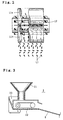
Fig.3 is a diagram showing a specific structure of the
quantitative feeder shown in Fig.1.
Fig.4 is a diagram illustrating the tilt angle of the
inner wall surface of the hopper and dimensions of the
individual zones of the screw in the injecting machine shown
in Fig.1.
Fig.5 shows flow charts of operation for controlling the
injecting machine shown in Fig.1.
Fig.6 is a diagram showing the structure of a stirring
device according to a second embodiment of the present
invention.
Fig.7 is a diagram showing the structure of a stirring
device according to a third embodiment of the present
invention.
Fig.8 is a diagram showing the part for supplying solids
of a thermoplastic substance in an injecting machine according
to a fourth embodiment of the present invention.
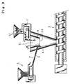
Fig.9 is a diagram showing the part for supplying solids
of a thermoplastic substance in an injecting machine according
to a fifth embodiment of the present invention.
Fig.10 is a diagram showing the part for supplying solids
of a thermoplastic substance in an injecting machine according
to a sixth embodiment of the present invention.
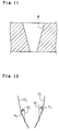
Fig.11 is a diagram showing a sectional structure of a
discharge passage of a discharge device according to a seventh
embodiment of the present invention.
Fig.12 is a diagram showing forms of cross lines formed by
a vertical plane and the inner wall surface of a discharge
passage of a discharge device of an eighth embodiment of the
present invention.
Fig.1 is a cross section of a plasticizing device
according to a first embodiment of the present invention,
which is formed of a discharge device for discharging solids
of a thermoplastic substance (solid thermoplastic substances)
and fibers, a cylinder coupled to the discharge device, and a
screw provided in the cylinder.
Referring to the drawing, the discharge device has a
hopper (4) extending in the longitudinal direction and having
an inner wall surface forming a passage, a discharge passage,
for the thermoplastic substances and fibers (hereinafter
referred to as a material supply passage) with its lower end
opened, means for supplying fibers of a certain length into
the material supply passage (hereinafter referred to as fiber
supply means) and means for supplying the solids of the
thermoplastic substance into the material supply passage
(hereinafter referred to as solid supply means). The fiber
supply means is provided above the hopper (4). While a lobing
cutter (1) for cutting fibers to a certain length and
supplying them, or a feeder for supplying chopped strand
fibers cut to a certain length at a constant rate can be
applied as the fiber supply means, the embodiment shown in
Fig.1 adopts the lobing cutter (1) as the fiber supply means.
The lobing cutter (1) has a first feeding roll (11a) and
a second feeding roll (11b) for feeding a plurality of longer
fibers (L) wound around a reel (19) in a spread state as shown
in Fig.2, and a cutting roll (12) provided on the exit side of
the feeding rolls (11a) and (11b) and having at least one
cutting edge (121) for cutting the longer fibers (L) fed from
the feeding rolls (11a) and (11b). The cutting roll (12) is
positioned so that its cutting edges contact with the second
feeding roll (11b) when rotating. In Fig.1, the cutting roll
(12), which rotates in the clockwise direction, is positioned
so that the cut fibers (L1) certainly fall inside the hopper
(4).
In the first embodiment shown in Fig.1, four lobing glass
fibers (2400 tex) are fed between the first feeding roll (11a)
and the second feeding roll (11b) as the plurality of longer
fibers (L). The fibers fed from the feeding rolls (11a) and
(11b) are cut by the cutting roll (12) into cut fibers (L1)
having a length of 14 mm. In this embodiment, the discharge
rate of the cut fibers (L1) from the lobing cutter (1) is set
to 2.2 kg/min.
The length of the cut fibers cut by the cutting roll (12)
can be mainly adjusted by changing the pitch of the cutting
edges (121) provided on the cutting roll. The lobing cutter
(1) shown in this diagram is adjusted to cut fibers to lengths
from about 3 to 50 mm. The discharge device of the invention
can be particularly effectively applied to fibers having
lengths ranging from about 3 to 50 mm. While the length of
the cut fibers (L1) usually somewhat varies with respect to
the set value, the discharge device and the plasticizing
device of the invention can smoothly deal with cut fibers
whose average length is in the above-mentioned range.
Feeders which can supply fibers cut to a predetermined
length into the material supply passage at a constant rate can
be used as the fiber supply means. That is to say, the feeder
has a motor-driven belt conveyer, and may further include an
inclined shoot for causing cut fibers so as to slip off.
A feeder (2) which can supply a thermoplastic substance in
solid form, e.g., pellets, particles, or powders, into the
material supply passage at constant rate can be used as the
solid supply means. For example, as shown in Fig.3, the
feeder (2) is equipped with a belt conveyer (22) driven by a
motor (23). A hopper (21) for accumulating the solids of the
thermoplastic substance is provided above the belt conveyer
(22). The feeder (2) also has an inclined shoot (6) on which
the solids of the thermoplastic substance slips down. The
shoot (6) is arranged so that the solids of the thermoplastic
substance flowing out from its end falls into the material
supply passage of the discharge device. The speed of the belt
conveyer (22) depends on the rotational speed of the motor
(23) for driving it. The amount of supply of the solids of
the thermoplastic material per unit time can be adjusted by
changing the speed of the belt conveyer (22). In this
embodiment, the speed for supplying the solids of the
thermoplastic substance from the feeder (2) is set to 5.1
kg/min.
In the use of the discharge device of the present
invention, denaturant for improving physical properties of the
thermoplastic substances or filler other than fibers may be
supplied into the material supply passage together with the
solids of the thermoplastic substance and fibers.
The plasticizing device of the present invention is
characterized in that it has the discharge device of the
invention.
The discharge device of the present invention is a
discharge device for discharging solids of a thermoplastic
substance and fibers, which includes a discharge passage
longitudinally extending without spreading at least downward
and having an inner wall surface forming a passage opened at
its lower end, solid supply means for supplying the solids of
the thermoplastic substance to a first position in the
passage, and fiber supply means for supplying the fibers to a
second position in the passage, wherein a cross line on which
a part of the inner wall surface extending downward from an
upper one of the first position and the second position
intersects a vertical plane passing through the opened end of
the passage forms an angle of 0 to 45°, preferably 0 to 30°,
and more preferably 0 to 15°, with respect to a vertical line.
It was confirmed that the thermoplastic substances and
fibers could be smoothly discharged from the opening at the
lower end of the material supply passage when the inner wall
surface forming the discharge passage of the discharge device
satisfied the above-mentioned condition. This embodiment
adopts the hopper (4) in the form of a circular truncated cone
whose generatrix and a vertical line form an angle, i.e., the
half vertex angle, of 10°. The inner wall surface of the
discharge device does not necessarily have to be shaped in
circular form in horizontal section, that is to say, it is not
limited to a circular truncated cone, but it may be shaped in
oval form, regular polygonal form, or asymmetric form in
horizontal section, as long as it satisfies the condition
mentioned above. The above-mentioned condition about the
angle is set to effectively prevent fibers having average
lengths from 3 to 50 mm from attaching to the inner wall
surface.
While the material of the member having the inner wall
surface is not particularly limited, it is preferable to use
a material which is not likely to generate static electricity.
In this embodiment, the hopper (4) is formed of a material
composed of a film (0.4 mm thick) of polyethylene
terephthalate and reinforcing stainless steel laid on its
outer surface. The hopper (4) may be equipped with a static
electricity removing device for spraying static electricity
removing air to parts where fibers are liable to attach due to
static electricity. In this embodiment, a vibration
generating device (43) such as a vibrator for vibrating the
hopper (4) is provided on the outer wall of the hopper (4) to
more certainly prevent fibers from attaching to the inner wall
surface of the hopper (4).
Further, when the amount of the accumulated fibers and
solids of the thermoplastic substance in the material supply
passage of the hopper (4) is within a certain range, the time
required for melting the thermoplastic substances in the
plasticizing device becomes stable. Accordingly, it is
preferred that the discharge device is equipped with means for
sensing the upper and lower limits of the level of the top
surface of the material in the material supply passage so as
to control the solid supply means and the fiber supply means
to start and stop. As such means, this embodiment provides an
upper switch (41) for sensing the upper limit of the top
surface of the accumulated material and a lower switch (42)
for sensing the lower limit of the top surface of the
accumulated material on the side of the hopper (4). The lower
switch (42) has a structure for starting the solid supply
means and the fiber supply means when the top surface of the
material in the material supply passage becomes lower than a
first level and the upper switch (41) has a structure for
stopping the solid supply means and the fiber supply means
when the top surface of the material in the material supply
passage becomes higher than a second level which is higher
than the first level. In this embodiment, the lower switch
(42) is attached to the hopper (4) at an interval of 150 mm
from the upper switch (41).
The discharge device of the invention preferably includes
a stirring device (60) for uniformly mixing the solids of the
thermoplastic substance and fibers in the material supply
passage. The stirring devices (60) in the first embodiment
shown in Fig.1 and the second embodiment shown in Fig.6 have
stirring blades (61) provided in a position higher than the
upper switch (41) and a motor (62) for rotating them. The
stirring blades (61) are located below the point where the cut
fibers (L1) discharged from the lobing cutter (1) and the
solids of the thermoplastic substance discharged from the
shoot (6) of the solid supply means meet, and stir and mix the
fibers and the solids of the thermoplastic substance. It is
preferable to stir the fibers and thermoplastic substances
without applying strong shearing force so as to prevent the
cut fibers (L1) from getting untwisted. Accordingly, in these
embodiments, the rotational speed of the stirring blades (61)
is set to 600 r.p.m.
As shown in a third embodiment of Fig.7, stirring blades
(63) may be attached to a rotating shaft (640) of a motor (64)
passed in the horizontal direction through the inner wall
surface of the hopper (4) with its end supported by a bearing
(69).
In the discharge device of the invention, a member against
which the joined fibers and thermoplastic substances collide
for changing the flowing direction of them may be provided in
place of the stirring devices (60) described above. For
example, as shown in the embodiment depicted in Fig.10, an
inner tube (5) to which the thermoplastic substances and
fibers are supplied from the feeders (2) and (7) may be
provided in the material supply passage with a cone-shaped
spreading member (66) suspended by wire (67) under the opening
at the lower end of the inner tube (5). With this structure,
the thermoplastic substances (P) and fibers (L1) falling
through the opening at the lower end of the inner tube (5)
strike the spreading member (66) to change their direction,
and the thermoplastic substances (P) and the fibers (L1) are
thus mixed.
Referring to the first embodiment again, the structure of
the injecting machine (3) as a plasticizing device for melting
the thermoplastic substances and kneading it with fibers, as
shown in Fig.4, is basically the same as that of a known
common screw type injecting machine. While the screw (31)
moves, as will be described later, backward in the axial
direction while rotating, the groove part (38) is preferably
dimensioned so that the region corresponding to the material
accepting inlet (37) always satisfies the following expression
while moving backward. That is to say, in ordinary cases in
which the caliber d (cm) of the material accepting inlet (37)
is equal to or larger than the groove width c (cm) of the
screw (31), the dimensions of the region corresponding to the
material accepting inlet (37) in the groove part (38) are
preferably set as shown below;
a 2 2π- b 2 2π × c ≧ 350 cm 3.
Where the outside diameter of the screw (31) including the
flight is taken as a (cm) and the diameter of the groove
bottom is taken as b (cm).
It can be confirmed that when the dimensions such as the
outside diameter "a" are set to satisfy the expression (1),
the material discharged and supplied from the hopper (4) can
be smoothly introduced to the screw (31).
While the boundaries between the bases of the flight and
the groove bottom are usually formed in circular arc form, the
value of the smallest part between the flight is selected as
the value of the groove diameter b in the expression (1).
When the caliber d of the material accepting inlet (37) is
smaller than the groove width c, the caliber d of the material
accepting inlet (37) is substituted in the left side of the
expression (1) in place of the groove width c, and the outside
diameter a of the screw (31) and the diameter b of the groove
are set to satisfy the modified expression (1).
In the case of an injecting machine, since the screw (31)
moves backward (in the left direction in the drawing) in the
axial direction while rotating, the groove (38) under the
material accepting inlet (37) also moves in the axial
direction. Accordingly, the values are set so that the groove
(38) coming under the material accepting inlet (37) while
moving always satisfies the expression (1).
Specific dimensions of the screw diameter a, the groove
diameter b and the groove width c are set as follows in this
embodiment: the screw diameter a = 12 cm, the groove diameter
b = 8.7 cm, and the groove width c = 10.8 cm. Accordingly,
the value on the right side of the expression (1) is set to
579 cm3 in this case. The caliber of the material accepting
inlet (37) is set to 12 cm.
To prevent fibers from being cut in the process of melting
and kneading in the injecting machine (3), a full-flight screw
is adopted as the screw (31). A mixing head (32) having a
check ring function for preventing the molten resin from
reversely flowing to the upstream when injected is attached to
an end of the screw (31). This screw (31) is divided into
three regions from the base end to the tip end, a feed zone
(311) corresponding to the material accepting inlet (37), a
compression zone (312) and a metering zone (313), in this
order. The groove depth in the feed zone (311) is set to 16.5
mm, the groove depth in the compression zone (312) is set so
that it gradually changes from 16.5 mm to 5.25 mm, and the
groove depth in the metering zone (313) is set to 5.25 mm.
The ratio among the lengths of the feed zone (311), the
compression zone (312) and the metering zone (313) of the
screw (31) is set to 2:1:1. The flight pitch of the screw
(31) in the individual zones is set to 120 mm and the groove
width c in the individual zones is set to 10.8 cm.
It is preferred that the compression ratio of this screw
(31) is set to 4 or smaller, preferably 1.5 to 4, and the
apparent shearing rate is set to 50 to 100 sec-1.
The compression ratio is given by the following equation:
Compression ratio = the groove depth in feed zone (311) /
the groove depth in metering zone (313).
The apparent shearing rate is given by the following equation:
Apparent shearing rate = πan/60H
Where
- a:
- diameter (cm) of screw (31),
- n:
- the rotational speed (r.p.m) of screw (31), and
- H:
- groove depth (cm).
In this embodiment, a compression ratio of 3.14 is used.
By setting the rotational speed of the screw (31) to 60
r.p.m., the apparent shearing rate is set to 71.8 sec-1.
The screw (31) is rotation-driven by a screw driving
device (33) and is controlled so that it reciprocates in the
axial direction.
The plasticizing device shown in Fig.1 is controlled by a
control device (not shown) which performs controlling
operation on the basis of the flow charts shown in Fig.5. The
control device includes two computers, a first computer which
operates according to the flow chart (1) in the figure and a
second computer which operates according to the flow chart
(2).
Operation of the device will be described referring to the
flow charts.
When the device is operated with thermoplastic substances
in pellet form (e.g., a polypropylene resin) supplied in the
hopper (21) of the quantitative feeder (2) and the ends of the
long reinforcing fibers (L) drawn from the reel (19) and
inserted between the feed rolls (11a)(11b), the first and
second computers start operating.
When the first computer starts, the lobing cutter (1), the
quantitative feeder (2) and the stirring device (60) are
driven in step (ST1). While the quantitative feeder (2) and
the lobing cutter (1) may be driven at the same time, or may
be driven at different timings, the quantitative feeder (2)
and the like are driven at such timing that the thermoplastic
substances and fibers can be simultaneously supplied to the
hopper (4).
When the lobing cutter (1) and the quantitative feeder (2)
start, fibers (L1) cut by operation of the lobing cutter (1)
fall from the fiber discharge outlet (52) of the inner tube
(5) into the hopper (4). The thermoplastic substances (P)
supplied from the quantitative feeder (2) is transferred on
the shoot (6) and is supplied into the hopper (4) from its
end. Then the fibers (L1) and the thermoplastic substances
(P) strike the stirring blades (61) of the stirring device
(60) and are stirred and mixed, and the mixture is accumulated
in the hopper (4).
Next, when the amount of the accumulated thermoplastic
substances (P) and the like supplied into the hopper (4)
increases until the top surface reaches the upper switch (41),
the upper switch (41) outputs a sense signal, which causes the
lobing cutter (1), the quantitative feeder (2) and the
stirring device (60) to stop (steps (ST2) (ST3)).
When the upper switch (41) outputs the sense signal, the
second computer performs steps (ST11) to (ST12) shown in the
flow chart (2) in Fig.5 to drive the injecting machine (3).
That is to say, it makes the screw driving device (33) move
the screw (31) backward in the axial direction while rotating
and makes a heater (not shown) provided on the external
surface of the cylinder (39) generate heat. Then the
thermoplastic substances (P) and the like are supplied from
the lower end of the hopper (4) into the cylinder (39) through
the material accepting inlet (37), which are transferred
toward the end of the screw (31) and heated by the heater so
that the thermoplastic substances (P) gradually melt. Then
when the amount of the accumulated molten mixture material
reaches a set value at the end of the screw (31), the screw
(31) is made to stop rotating (steps (ST13)(ST14)).
Subsequently, the screw (31) is advanced in the axial
direction by the screw driving device (33). Then the mixing
head (32) having a check ring function discharges the molten
mixture material from the discharge outlet (36) at the end of
the cylinder (39), which is injected into a mold (not shown)
and formed into products.
In the course of the above-described operation, when the
top surface of the accumulated thermoplastic substances (P)
and the like in the hopper (4) decreases under the lower
switch (42), the first computer executes step (ST4) shown in
the flow chart (1) in Fig.5 to start the lobing cutter (1) and
the like again in step (ST1). This way, the top surface of
the accumulated thermoplastic substances (P) and the like in
the hopper (4) is always kept in the level between the upper
switch (41) and the lower switch (42).
When producing molded products of fiber-reinforced resin
by melting and mixing a polypropylene resin and glass fibers
by using the injecting machine of the embodiments above, cut
fibers (L1) having an average length of 14 mm were supplied at
a rate of 2.2 Kg/min from the lobing cutter (1) and resin
pellets were supplied at a rate of 5.1 Kg/min from the
quantitative feeder (2). As a result, while it took about 18
sec to bring the mixed material of 2 Kg into a molten state,
this time period was always stable and the fibers and
thermoplastic substances were smoothly supplied into the
injecting machine (3) as a plasticizing device without making
the hopper (4) clogged.
While the fibers and the like hardly attach to the inner
wall of the hopper (4) when the inclination angle of the
inner wall surface of the hopper (4) is set to not less than
0° nor more than 30° as stated above, it was confirmed that
the fibers attach to the inner wall surface of the hopper (4)
even under the same conditions when a hopper (4) with an
inclination angle of 50° is used.
Although the embodiments described above use the screw
(31) with which the value on the right side in the expression
(1) is set to 579 cm3, fibers and the like were smoothly
supplied to the screw (31) when that value was 350 cm3, as
well.
The embodiments described above have shown systems in
which the thermoplastic substances (P) from the shoot (6) is
joined from the transverse direction into the falling cut
fibers (L1). However, as shown in the fourth embodiment shown
in Fig.8, the quantitative feeder (2) may be provided above
the lobing cutter (1) such that the thermoplastic substances
(P) freely falls in the gap between an inner tube (80) and the
hopper (4). In this case, the cut fibers (L1) flow down to
the vicinity of the stirring blades (63) while being
surrounded by the thermoplastic substances (P) and they are
stirred and mixed there. This method does not require the
shoot (6) in the embodiments shown in Fig.1 and Fig.7.
As shown in the embodiments above, in a discharge device
having the hopper (4) for discharging fibers and thermoplastic
substances, the fibers and thermoplastic substances may be
directly supplied into the hopper (4). In order to more
uniformly mix the two and lead them to the plasticizing device
smoothly, it is more preferable, as shown in the fifth
embodiment shown in Fig.9, to supply fibers into the hopper
(4) through an inner tube (5) provided in the hopper (4) and
having at least its lower end opened and supply the
thermoplastic substances between the outer periphery of the
inner tube (5) and the inner periphery of the hopper (4).
In this case, it is preferred that the inner tube (5) is
formed of a material not liable to generate static
electricity, as well as the hopper (4). As for the shape of
the inner tube (5), the fiber inlet (51) and the fiber outlet
(52) at its upper and lower ends may be equally sized, or
either one of them may be sized larger. When using one in the
shape of a reverse cone as shown in the drawing, the
inclination angle ' of the inner wall surface of the inner
tube (5) with respect to a vertical line is preferably 30° or
smaller, and desirably 15° or smaller. When the angle is set
this way, the effect of preventing cut fibers (L1) from
attaching is remarkably exhibited. In order to more certainly
prevent cut fibers (L1) from attaching to the inner wall
surface of the inner tube (5), a vibration generating device,
such as a vibrator, may be provided to vibrate the inner tube
(5). Further, the thermoplastic substances (P) supplied from
the shoot (6) may be made to collide with the inner tube (5)
as shown in Fig.9 to vibrate the inner tube (5). Further,
stirring blades may be provided to stir and mix the
thermoplastic substances (P) and fibers (L1) which meet under
the inner tube (5).
Although the embodiment illustrated in Fig.1 has shown a
system in which cut fibers (L1) are formed by using a lobing
cutter, fibers (L1) may be supplied into the inner tube (5)
from a quantitative feeder (7) which can quantitatively supply
chopped strand fibers previously cut to certain length, as
shown in the embodiment in Fig.9.
Although the embodiments shown above have described an
injecting machine as an example of a plasticizing device, the
present invention can also be applied when the plasticizing
device is an extruding machine for thermoplastic substances.
The above-described embodiments adopt the tubular hopper
(4) whose inner wall surface is inclined at an angle in a
given range as a discharge passage of the discharge device.
However, the discharge passage is not limited to a tubular
hopper, but any structure having an inner wall surface W
inclined at a given angle as shown in the seventh embodiment
shown in Fig.11 provides the same effects as the embodiments
above.
The above-described embodiments adopt a discharge passage
of the discharge device whose inner wall surface intersects a
vertical plane to form linear cross lines. However, the cross
lines CL may draw curves as shown in the eighth embodiment in
Fig.12. In this case, when the discharge passage is formed so
that tangent lines TL at individual points on the cross lines
CL and vertical lines VL form angles in the range from 0 to
45°, preferably 0 to 30°, more preferably 0 to 15°, the same
effects as those of the above-described embodiments can be
obtained.
While the invention has been described in detail, the
foregoing description is in all aspects illustrative and not
restrictive. It is understood that numerous other
modifications and variations can be devised without departing
from the scope of the invention.