EP0848987A1 - Hollow fiber module - Google Patents
Hollow fiber module Download PDFInfo
- Publication number
- EP0848987A1 EP0848987A1 EP97121631A EP97121631A EP0848987A1 EP 0848987 A1 EP0848987 A1 EP 0848987A1 EP 97121631 A EP97121631 A EP 97121631A EP 97121631 A EP97121631 A EP 97121631A EP 0848987 A1 EP0848987 A1 EP 0848987A1
- Authority
- EP
- European Patent Office
- Prior art keywords
- hollow fiber
- hollow
- fiber module
- hollow fibers
- distribution
- Prior art date
- Legal status (The legal status is an assumption and is not a legal conclusion. Google has not performed a legal analysis and makes no representation as to the accuracy of the status listed.)
- Granted
Links
- 239000012510 hollow fiber Substances 0.000 title claims description 67
- 238000009826 distribution Methods 0.000 claims abstract description 32
- 239000008280 blood Substances 0.000 claims abstract description 11
- 210000004369 blood Anatomy 0.000 claims abstract description 11
- 238000012856 packing Methods 0.000 claims abstract description 5
- 238000011282 treatment Methods 0.000 claims abstract description 3
- 238000001914 filtration Methods 0.000 claims description 3
- 238000001631 haemodialysis Methods 0.000 claims description 3
- 230000000322 hemodialysis Effects 0.000 claims description 3
- 239000000835 fiber Substances 0.000 abstract description 3
- 150000001875 compounds Chemical class 0.000 description 3
- 239000007788 liquid Substances 0.000 description 3
- 239000000463 material Substances 0.000 description 3
- 239000012528 membrane Substances 0.000 description 3
- 229920002678 cellulose Polymers 0.000 description 2
- 239000001913 cellulose Substances 0.000 description 2
- 238000000502 dialysis Methods 0.000 description 2
- 238000004519 manufacturing process Methods 0.000 description 2
- 238000004382 potting Methods 0.000 description 2
- 230000036770 blood supply Effects 0.000 description 1
- 229920002301 cellulose acetate Polymers 0.000 description 1
- 238000010276 construction Methods 0.000 description 1
- 238000011161 development Methods 0.000 description 1
- 230000018109 developmental process Effects 0.000 description 1
- 238000010586 diagram Methods 0.000 description 1
- 239000004744 fabric Substances 0.000 description 1
- 239000000706 filtrate Substances 0.000 description 1
- 239000012530 fluid Substances 0.000 description 1
- 238000002615 hemofiltration Methods 0.000 description 1
- 238000000034 method Methods 0.000 description 1
- 238000006213 oxygenation reaction Methods 0.000 description 1
- 239000012466 permeate Substances 0.000 description 1
- 229920002239 polyacrylonitrile Polymers 0.000 description 1
- 239000011148 porous material Substances 0.000 description 1
- 239000000047 product Substances 0.000 description 1
- 238000007789 sealing Methods 0.000 description 1
- 238000000926 separation method Methods 0.000 description 1
- 238000009987 spinning Methods 0.000 description 1
- 239000000126 substance Substances 0.000 description 1
- 229920002994 synthetic fiber Polymers 0.000 description 1
- 230000009885 systemic effect Effects 0.000 description 1
- 238000012546 transfer Methods 0.000 description 1
- 230000002485 urinary effect Effects 0.000 description 1
- XLYOFNOQVPJJNP-UHFFFAOYSA-N water Substances O XLYOFNOQVPJJNP-UHFFFAOYSA-N 0.000 description 1
Images
Classifications
-
- B—PERFORMING OPERATIONS; TRANSPORTING
- B01—PHYSICAL OR CHEMICAL PROCESSES OR APPARATUS IN GENERAL
- B01D—SEPARATION
- B01D63/00—Apparatus in general for separation processes using semi-permeable membranes
- B01D63/02—Hollow fibre modules
- B01D63/033—Specific distribution of fibres within one potting or tube-sheet
-
- F—MECHANICAL ENGINEERING; LIGHTING; HEATING; WEAPONS; BLASTING
- F28—HEAT EXCHANGE IN GENERAL
- F28F—DETAILS OF HEAT-EXCHANGE AND HEAT-TRANSFER APPARATUS, OF GENERAL APPLICATION
- F28F21/00—Constructions of heat-exchange apparatus characterised by the selection of particular materials
- F28F21/06—Constructions of heat-exchange apparatus characterised by the selection of particular materials of plastics material
- F28F21/062—Constructions of heat-exchange apparatus characterised by the selection of particular materials of plastics material the heat-exchange apparatus employing tubular conduits
-
- B—PERFORMING OPERATIONS; TRANSPORTING
- B01—PHYSICAL OR CHEMICAL PROCESSES OR APPARATUS IN GENERAL
- B01D—SEPARATION
- B01D63/00—Apparatus in general for separation processes using semi-permeable membranes
- B01D63/02—Hollow fibre modules
-
- B—PERFORMING OPERATIONS; TRANSPORTING
- B01—PHYSICAL OR CHEMICAL PROCESSES OR APPARATUS IN GENERAL
- B01D—SEPARATION
- B01D2313/00—Details relating to membrane modules or apparatus
- B01D2313/10—Specific supply elements
-
- B—PERFORMING OPERATIONS; TRANSPORTING
- B01—PHYSICAL OR CHEMICAL PROCESSES OR APPARATUS IN GENERAL
- B01D—SEPARATION
- B01D2319/00—Membrane assemblies within one housing
- B01D2319/06—Use of membranes of different materials or properties within one module
Definitions
- the invention relates to a hollow fiber module for filtration, especially for the treatment of blood, such as dialysis, Hemofiltration, oxygenation, plasma separation or blood heat exchangers.
- Today's hollow fiber modules mostly consist of one tubular housing, in the coaxial a variety of parallel Hollow fibers are introduced, with the exception of those to be kept open End of the hollow fibers with potting compound sealed together and with the inner wall of the housing will.
- the two housing ends are also with each an end cap over which in case of use as a dialyzer the blood supply and blood drainage takes place.
- the tube has near the potted ends an inlet and an outlet for an exchange liquid. While the blood passes through the hollow fibers flows, it is from the exchange liquid, for example a dialysate, around which, in this case microporous hollow fiber walls a selective Enable mass exchange. If the hollow fiber module as Filtration device is used, so there is no exchange fluid worked and the sockets serve as drainage paths for the filtrate.
- the aspirations go to the largest possible exchange area with minimal blood refill volume in one to accommodate the smallest possible housing volume, in particular the size of the disposable hollow fiber modules for cost reasons to keep as low as possible.
- the membrane outer walls of the hollow fibers have to be completely washed around with only a slight flow resistance.
- this ideal state cannot be achieved with a bundling of, for example, 500 to 15,000 smooth, elastic and circular hollow fibers per cm 2 cross-sectional area.
- the hollow fibers nestle against one another or even stick together over their entire length, which increases the flow resistance and considerably reduces the exchange area.
- the cross-sectional area can be considerable can be reduced without the spacing of the hollow fibers from one another thereby diminishes.
- the reduction of Cross-section enables better and above all excellent channeled, uniform rinsing of the hollow fibers with reduced flow resistance and thus a larger one Efficiency for a given size of a hollow fiber module.
- the maximum cross-sectional extension of the distribution threads correspond to a further version maximum the diameter of the Hollow fibers.
- distribution threads can also be via their length may be wavy or curled.
- Hollow fibers and distribution threads are preferred in a ratio that is variable in a wide range, the packing density of the hollow fibers in the hollow fiber module to change according to the respective requirements.
- Hollow fiber module is hemodialysis.
- the hollow fiber module shown in Fig. 1 consists of a cylindrical housing 1, each end by means of End caps 2 is sealed. the end caps 2 are each provided with connecting piece 3, which is coaxial to the cylindrical Housing 1 lie.
- the housing 1 are essentially a plurality of hollow fibers 4 parallel to one another and distribution threads 5 well mixed. Their ends are each with each other and to the inner wall of the Housing 1 sealed by potting compound 6, the Hollow fibers 4 themselves remain open on the front and so from a connecting piece 3 to the other connecting piece 3 can be flowed through by the blood.
- two additional connecting pieces 7 are formed radially protruding, which serve as dialysate inlet and dialysate outlet.
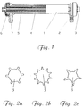
- Fig. 2 shows different forms of the outer cross section of Distribution threads 5, all of which are very light and without effort with a corresponding spinneret, for example extruded from a cellulose spinning solution.
Abstract
Description
Die Erfindung betrifft einen Hohlfasermodul zur Filtration, insbesondere zur Behandlung von Blut, wie Dialyse, Hämofiltration, Oxygenation, Plasmaseparation oder Blutwärmetauscher.The invention relates to a hollow fiber module for filtration, especially for the treatment of blood, such as dialysis, Hemofiltration, oxygenation, plasma separation or blood heat exchangers.
Hohlfasermodule heutiger Bauart bestehen zumeist aus einem rohrförmigen Gehäuse, in das koaxial eine Vielzahl paralleler Hohlfasern eingeführt sind, die mit Ausnahme der offenzuhaltenden Enden der Hohlfasern endseitig mit Vergußmasse miteinander und mit der Gehäuseinnenwand dicht vergossen werden. Die beiden Gehäuseenden sind ferner mit je einer Endkappe abgeschlossen, über die im Falle des Einsatzes als Dialysator die Blutzufuhr und Blutableitung erfolgt. Weiterhin hat das Rohr in Nähe der vergossenen Enden einen Einlaß- und einen Auslaßstutzen für eine Austauschflüssigkeit. Während das Blut durch die Hohlfasern fließt, wird es von der Austauschflüssigkeit, beispielsweise einem Dialysat, umspült, wobei die in diesem Fall mikroporös auszubildenden Hohlfaserwände einen selektiven Stoffaustausch ermöglichen. Wird der Hohlfasermodul als Filtrationsgerät benutzt, so wird ohne Austauschflüssigkeit gearbeitet und die Stutzen dienen als Ablaufwege für das Filtrat.Today's hollow fiber modules mostly consist of one tubular housing, in the coaxial a variety of parallel Hollow fibers are introduced, with the exception of those to be kept open End of the hollow fibers with potting compound sealed together and with the inner wall of the housing will. The two housing ends are also with each an end cap over which in case of use as a dialyzer the blood supply and blood drainage takes place. Furthermore, the tube has near the potted ends an inlet and an outlet for an exchange liquid. While the blood passes through the hollow fibers flows, it is from the exchange liquid, for example a dialysate, around which, in this case microporous hollow fiber walls a selective Enable mass exchange. If the hollow fiber module as Filtration device is used, so there is no exchange fluid worked and the sockets serve as drainage paths for the filtrate.
Die Bestrebungen gehen dahin, eine möglichst große Austauschfläche mit minimalem Blutauffüllvolumen in einem möglichst kleinen Gehäusevolumen unterzubringen, um insbesondere aus Kostengründen die Baugröße der Einweg-Hohlfasermodule möglichst gering zu halten. The aspirations go to the largest possible exchange area with minimal blood refill volume in one to accommodate the smallest possible housing volume, in particular the size of the disposable hollow fiber modules for cost reasons to keep as low as possible.
Um den Stoff- und/oder Wärmeaustausch zwischen dem in den Hohlfasern geführten Blut und der Austauschflüssigkeit zu maximieren, müssen andererseits die Membranaußenwände der Hohlfasern vollständig und mit nur geringem Strömungswiderstand umspült werden. Dieser Idealzustand ist jedoch bei einer Bündelung von z.B. 500 bis 15000 glatter, elastischer und kreisrunder Hohlfasern je cm2 Querschnittsfläche nicht zu erreichen. Die Hohlfasern schmiegen sich aneinander oder haften gar über ihre gesamte Länge aneinander, wodurch sich der Strömungswiderstand erhöht und die Austauschfläche erheblich verkleinert.In order to maximize the mass and / or heat exchange between the blood carried in the hollow fibers and the exchange liquid, on the other hand, the membrane outer walls of the hollow fibers have to be completely washed around with only a slight flow resistance. However, this ideal state cannot be achieved with a bundling of, for example, 500 to 15,000 smooth, elastic and circular hollow fibers per cm 2 cross-sectional area. The hollow fibers nestle against one another or even stick together over their entire length, which increases the flow resistance and considerably reduces the exchange area.
Zur Beseitigung dieses Übelstandes, wurde bereits vorgeschlagen, die Hohlfasern mit Längsrippen (DE-OS 28 42 836, DE-OS 29 10 568), Ausbauchungen (DE-OS 28 42 957) oder Ondulierungen (DE-OS 28 42 958, DE-OS 30 09 528) zu extrudieren, bzw. auf die Außenseiten glatter Hohlfasern abstandgebendes Material anzulagern (DE 36 36 583 A1). Weiterhin sind Hohlfasermodule bekannt, die die Hohlfasern in Form eines Vollgeflechts (EP 0 193 946 A2) oder Gewebes (EP 0 289 812 A1) enthalten. Alle genannten Vorschläge sind vom Anmelder ausführlich in der deutschen Patentschrift DE 196 52 695 C1 gewürdigt worden, weshalb an dieser Stelle darauf nicht näher eingegangen werden soll.To remedy this problem, it has already been proposed the hollow fibers with longitudinal ribs (DE-OS 28 42 836, DE-OS 29 10 568), bulges (DE-OS 28 42 957) or undulations (DE-OS 28 42 958, DE-OS 30 09 528) to extrude, or spacing on the outside of smooth hollow fibers Add material (DE 36 36 583 A1). Farther Hollow fiber modules are known which in the hollow fibers Form of a full braid (EP 0 193 946 A2) or fabric (EP 0 289 812 A1). All the suggestions mentioned are detailed by the applicant in the German patent specification DE 196 52 695 C1 has been recognized, which is why I do not want to go into this in more detail.
Eine andere Methode zur Verbesserung des Stoff- oder Wärmeaustauschs besteht darin, daß das Hohlfaserbündel mit Distributionsfäden, die die Hohlfasern untereinander auf Abstand halten, durchmischt ist. Die Herstellung eines solchen Bündels bereitet keinerlei technische Schwierigkeiten und es ist praktisch jede gewünschte Packungsdichte an Hohlfasern erreichbar. Die Distributionsfäden sind entweder feinste Multifilamentfäden oder Monofile mit rundem Querschnitt. Für Dialysezwecke werden die vorzugsweise texturierten Distributionsfäden in einem im weiten Bereich variierbaren Verhältnis zugemischt. Nachteilig an diesen gemischten Bündeln ist, daß infolge des durch die Distributionsfäden verringerten Durchströmungsquerschnittes bei gleichbleibender Durchströmungsleistung der Druckabfall permeat-seitig steigt.Another method to improve mass or heat exchange is that the hollow fiber bundle with Distribution threads that the hollow fibers on each other Keep your distance, is mixed. The making of a such bundles presents no technical difficulties and it is practically any packing density desired accessible on hollow fibers. The distribution threads are either finest multifilament threads or monofilaments with round Cross-section. They are preferred for dialysis purposes textured distribution threads in a wide range variable ratio admixed. A disadvantage of this mixed bundles is that as a result of through the distribution threads reduced flow cross-section constant flow rate the pressure drop increases on the permeate side.
Aus der WO 93/19839 ist es bekannt, ein Faserbündel herzustellen, das aus lagenförmig übereinander angeordneten Hohlfasern und zwischen den Hohlfaserlagen angeordneten Distributionsfadenlagen besteht, wobei sich die Hohlfasern und Distributionsfäden an mehreren Stellen überkreuzen. Hierdurch kann der Anteil der Distributionsfäden ohne Leistungsverlust verringert werden. Allerdings ist die Herstellung dieser Lagen technisch aufwendig.From WO 93/19839 it is known to produce a fiber bundle the layered one above the other Hollow fibers and arranged between the hollow fiber layers Distribution thread layers exist, whereby the hollow fibers and cross distribution threads in several places. This allows the share of the distribution threads without Power loss can be reduced. However, it is Production of these layers is technically complex.
Der vorliegenden Erfindung liegt die Aufgabe zugrunde, ein Hohlfasermodul der eingangs beschriebenen Art zur Verfügung zu stellen, der sich durch große Leistung, kleine Bauweise sowie einfache und damit kostengünstige Herstellung auszeichnet.The present invention is based on the object Hollow fiber module of the type described above is available to stand out by great performance, small Construction as well as simple and therefore inexpensive manufacture distinguished.
Die Aufgabe wird erfindungsgemäß durch die im kennzeichnenden
Teil des Anspruchs 1 angegebenen Merkmale gelöst.
Vorteilhafte Weiterbildungen sind in den Ansprüchen 2 bis
7 aufgezeigt.The object is achieved by the in the characterizing
Part of
Indem die Distributionsfäden einen profilierten Querschnitt aufweisen, kann deren Querschnittsfläche erheblich reduziert werden, ohne daß der Abstand der Hohlfasern zueinander sich dadurch verringert. Die Reduzierung des Querschnitts ermöglicht eine bessere und vor allem hervorragend kanalisierte, gleichmäßige Umspülung der Hohlfasern bei verringertem Strömungswiderstand und somit einen größeren Wirkungsgrad bei vorgegebener Größe eines Hohlfasermoduls.By giving the distribution threads a profiled cross-section have, the cross-sectional area can be considerable can be reduced without the spacing of the hollow fibers from one another thereby diminishes. The reduction of Cross-section enables better and above all excellent channeled, uniform rinsing of the hollow fibers with reduced flow resistance and thus a larger one Efficiency for a given size of a hollow fiber module.
Profilierte Distributionsfäden lassen sich wesentlich einfacher herstellen als etwa profilierte Hohlfasern, da hier die Gefahr von Fehlstellen, das heißt Rissen oder Löchern, in der Hohlfasermembran nicht vorhanden ist. Weiterhin besteht nicht der systembedingte Nachteil, daß die über die ganze Länge des Hohlfasermoduls profilierten Bereiche die wirksame Austausch-Oberfläche der Hohlfasern vermindern.Profiled distribution threads are much easier produce as profiled hollow fibers, because here the risk of missing parts, i.e. cracks or holes, is not present in the hollow fiber membrane. Still exists not the systemic disadvantage that the over the entire length of the hollow fiber module profiled areas reduce the effective exchange surface of the hollow fibers.
Nach einer bevorzugten Ausführung ist das Außenprofil im Querschnitt kreisrund und mit zacken- bzw. rippenförmigen Abstrebungen ausgestaltet.According to a preferred embodiment, the outer profile is in the Cross section circular and with serrated or rib-shaped Designed struts.
In weiterer Ausgestaltung streben mindestens 4 Zacken oder Rippen radial vom Fadenkern ab.In a further embodiment, at least 4 peaks or strive Ribs radially from the thread core.
Die maximale Querschnittserstreckung der Distributionsfäden, gemessen diagonal über die Spitzen, entsprechen nach einer weiteren Ausführung maximal dem Durchmesser der Hohlfasern.The maximum cross-sectional extension of the distribution threads, measured diagonally over the tips, correspond to a further version maximum the diameter of the Hollow fibers.
Weiterhin können die Distributionsfäden zusätzlich über ihre Länge gewellt oder gelockt sein.Furthermore, the distribution threads can also be via their length may be wavy or curled.
Vorzugsweise werden Hohlfasern und Distributionsfäden in einem im weiten Bereich variierbaren Verhältnis gemischt, um die Packungsdichte der Hohlfasern im Hohlfasermodul entsprechend den jeweiligen Anforderungen zu ändern.Hollow fibers and distribution threads are preferred in a ratio that is variable in a wide range, the packing density of the hollow fibers in the hollow fiber module to change according to the respective requirements.
Eine bevorzugtes Anwendungsgebiet des erfindungsgemäßen Hohlfasermoduls ist die Hämodialyse.A preferred application of the invention Hollow fiber module is hemodialysis.
Die Erfindung soll anhand eines Ausführungsbeispiels näher erläutert werden. In der zugehörigen Zeichnung zeigt:
- Fig. 1
- einen Schnitt durch ein Hohlfasermodul (Prinzipskizze), geeignet für Hämodialyse.
- Fig. 2a bis 2c
- verschiedene Ausgestaltungsformen des Außenprofils von Distributionsfäden.
- Fig. 1
- a section through a hollow fiber module (schematic diagram), suitable for hemodialysis.
- 2a to 2c
- Different designs of the outer profile of distribution threads.
Das in Fig. 1 dargestellte Hohlfasermodul besteht aus einem
zylindrischen Gehäuse 1, das jeweils endseitig mittels
Endkappen 2 abgedichtet ist. die Endkappen 2 sind jeweils
mit Anschlußstutzen 3 versehen, die koaxial zum zylindrischen
Gehäuse 1 liegen. In dem Gehäuse 1 sind im wesentlichen
parallel zueinander eine Vielzahl von Hohlfasern 4
und Distributionsfäden 5 gut durchmischt untergebracht.
Deren Enden sind jeweils miteinander und zur Innenwand des
Gehäuses 1 durch Vergußmasse 6 dicht vergossen, wobei die
Hohlfasern 4 selbst jedoch stirnseitig offen bleiben und
so von einem Anschlußstutzen 3 zum anderen Anschlußstutzen
3 vom Blut durchströmt werden können. Zur Bildung eines
zweiten Durchströmungsraumes sind in die Wand des Gehäuses
1 zwei weitere Anschlußstutzen 7 radial abstehend eingeformt,
die als Dialysateinlaß und Dialysatauslaß dienen.The hollow fiber module shown in Fig. 1 consists of a
Die Hohlfasern 4 haben einen kreisringförmigen Querschnitt
und über ihre Länge eine gleichmäßige lichte Weite, wodurch
das Blut schonend hindurchgeleitet werden kann. Sie
haben ferner eine einheitliche Wanddicke und einen einheitlichen
Außendurchmesser. Die Wände der Hohlfasern 4
sind semipermeabel und somit für einen Stoffaustausch geeignet.
Vornehmlich werden aus dem zu dialysierenden Blut
des Patienten durch die Wände der Hohlfasern 4 hindurch
die zu eleminierenden harnpflichtigen Substanzen und Wasser
entzogen und mit dem Dialysat abgeführt. Der Porendurchmesser
in den Membranwänden der Hohlfasern 4 beträgt
etwa 1,5 bis 2 Nanometer, der Außendurchmesser der Hohlfasern
beträgt beispielsweise 150 bis 400 Mikrometer, die
Wandstärke 2 bis 50 Mikrometer. Die Hohlfasern 4 bestehen
aus synthetischem Material, beispielsweise Polyacrylnitril,
oder sind Naturfaserprodukte, wie reine Cellulose
oder Celluloseacetat.The
Verteilt zwischen mehreren Tausend Hohlfasern 4 je Hohlfasermodul
liegen die Distributionsfäden 5. Ihr Durchmesser
über die Spitzen ist erheblich kleiner, höchstens aber
gleich dem Durchmesser der Hohlfasern 4 und ihre Anzahl
ist so auf die Anzahl der Hohlfasern 4 abgestimmt, daß
sich eine Packungsdichte an Hohlfasern von 30% bis 40%
innerhalb des Gehäuses 1 ergibt. Die Distributionsfäden 5
können aus demselben Material wie die Hohlfasern 4, aber
auch aus unterschiedlichem Material bestehen. Vorteilhafterweise
kann mit jeder dritten Düse eines Spinndüsenblocks
zugleich mit den Hohlfasern 4 ein Distributionsfaden
5 der oben beschriebenen Art hergestellt werden.Distributed between several thousand
Fig. 2 zeigt verschiedene Formen des Außenquerschnitts von
Distributionsfäden 5, die sich allesamt sehr leicht und
ohne Aufwand mit einer entsprechenden Spinndüse, beispielsweise
aus einer Cellulose-Spinnlösung, extrudieren lassen.Fig. 2 shows different forms of the outer cross section of
In Fig. 2a ist ein kreisförmiger Querschnitt gezeigt, von
dem sechs Rippen so abstreben, daß eine anliegende Hohlfaser
4 maximal zwei Rippenspitzen berührt, nicht aber den
Kerndurchmesser. Dadurch verbleibt genügend Raum zur freien
Umspülung der Hohlfasern 4 mit Dialysat.In Fig. 2a a circular cross section is shown, from
strive the six ribs so that an adjacent
In Fig. 2b ist ein kreisförmiger Querschnitt mit zehn radialen Rippen dargestellt.2b is a circular cross section with ten radial ones Ribs shown.
In Fig. 2c ist ein weiterer Querschnitt dargestellt, der sich durch einen verhältnismäßig kleinen Kerndurchmesser und fünf entsprechend längeren Zacken auszeichnet.A further cross section is shown in FIG. 2c by a relatively small core diameter and five corresponding longer spikes.
Natürlich ist der Gegenstand der Erfindung nicht auf die dargestellten Ausführungsformen begrenzt, sondern umfaßt alle zweckmäßig profilierten und ggf. gewellten oder gedrillten Distributionsfäden. Of course, the subject of the invention is not on the illustrated embodiments limited, but includes all appropriately profiled and, if necessary, corrugated or drilled Distribution threads.
- Gehäusecasing
- 11
- EndkappeEnd cap
- 22nd
- AnschlußstutzenConnecting piece
- 33rd
- HohlfasernHollow fibers
- 44th
- DistributionsfädenDistribution threads
- 55
- VergußmasseSealing compound
- 66
- AnschlußstutzenConnecting piece
- 77
Claims (7)
Applications Claiming Priority (2)
| Application Number | Priority Date | Filing Date | Title |
|---|---|---|---|
| DE19652695A DE19652695C1 (en) | 1996-12-18 | 1996-12-18 | Hollow fibre module e.g. for blood dialysis, filtration, oxygenation, etc. |
| DE19652695 | 1996-12-18 |
Publications (2)
| Publication Number | Publication Date |
|---|---|
| EP0848987A1 true EP0848987A1 (en) | 1998-06-24 |
| EP0848987B1 EP0848987B1 (en) | 1998-12-23 |
Family
ID=7815144
Family Applications (1)
| Application Number | Title | Priority Date | Filing Date |
|---|---|---|---|
| EP97121631A Expired - Lifetime EP0848987B1 (en) | 1996-12-18 | 1997-12-09 | Hollow fiber module |
Country Status (3)
| Country | Link |
|---|---|
| EP (1) | EP0848987B1 (en) |
| DE (1) | DE19652695C1 (en) |
| ES (1) | ES2127029T3 (en) |
Cited By (4)
| Publication number | Priority date | Publication date | Assignee | Title |
|---|---|---|---|---|
| CN101862598A (en) * | 2010-06-25 | 2010-10-20 | 苏州顶裕节能设备有限公司 | Hollow fiber ultra-filtration membrane assembly having improved shell structure |
| EP3482817A1 (en) | 2017-11-09 | 2019-05-15 | Frank Wiese | Membrane bundle presentation with spacers |
| WO2019092105A1 (en) | 2017-11-09 | 2019-05-16 | Frank Wiese | Membrane bundle package having spacers |
| US11674241B2 (en) | 2018-01-31 | 2023-06-13 | Saudi Arabian Oil Company | Producing fibers using spinnerets |
Families Citing this family (2)
| Publication number | Priority date | Publication date | Assignee | Title |
|---|---|---|---|---|
| US7938386B2 (en) * | 2006-03-13 | 2011-05-10 | GM Global Technology Operations LLC | Fuel cell air humidifier |
| DE102012204705A1 (en) * | 2012-03-23 | 2013-09-26 | Raumedic Ag | Heat exchanger for an oxygenator and method of making such a heat exchanger |
Citations (3)
| Publication number | Priority date | Publication date | Assignee | Title |
|---|---|---|---|---|
| EP0186293A2 (en) * | 1984-11-16 | 1986-07-02 | Teijin Limited | Blood treatment device |
| DE3805414C1 (en) * | 1988-02-22 | 1989-09-07 | Secon Gesellschaft Fuer Separations- Und Concentrationstechnik Mbh, 3402 Dransfeld, De | |
| EP0464737A1 (en) * | 1990-07-02 | 1992-01-08 | ASAHI MEDICAL Co., Ltd. | A bundle of permselective hollow fibers and a fluid separator containing the same |
Family Cites Families (9)
| Publication number | Priority date | Publication date | Assignee | Title |
|---|---|---|---|---|
| DE2910568A1 (en) * | 1978-07-31 | 1980-09-25 | Akzo Gmbh | Hollow synthetic polymer filament with membrane layer |
| DE2842958A1 (en) * | 1978-10-02 | 1980-04-10 | Akzo Gmbh | Dialysis membrane comprising hollow cellulose fibre - with improved exchange surface in wavy form, mfd. from cuprammonium soln. of cellulose |
| DE2842957A1 (en) * | 1978-10-02 | 1980-04-10 | Akzo Gmbh | Dialysis membrane comprising hollow cellulose fibre - with improved exchange surface, extruded from cuprammonium soln. of cellulose |
| DE2842836A1 (en) * | 1978-10-02 | 1980-04-17 | Akzo Gmbh | Dialysis membrane comprising hollow cellulose fibre - with improved exchange surface in wavy form, mfd. from cuprammonium soln. of cellulose |
| IT1140712B (en) * | 1979-03-12 | 1986-10-01 | Extracorporeal Med Spec | HOLLOW FIBERS WITH UNEQUAL SECTION |
| DE8506819U1 (en) * | 1985-03-08 | 1986-07-03 | Akzo Gmbh, 5600 Wuppertal | Device for heat and / or mass transfer with the aid of hollow fibers |
| DE3636583A1 (en) * | 1986-10-28 | 1988-05-05 | Draegerwerk Ag | METHOD FOR PRODUCING A HOLLOW FIBER FABRIC EXCHANGE MODULE AND MODULE PRODUCED BY THIS METHOD |
| DE3715145A1 (en) * | 1987-05-07 | 1988-12-01 | Preh Elektro Feinmechanik | AIR DRAINING DEVICE |
| DE59301346D1 (en) * | 1992-03-27 | 1996-02-15 | Akzo Nobel Nv | HOLLOW THREAD BUNDLE AND METHOD AND DEVICE FOR ITS PRODUCTION |
-
1996
- 1996-12-18 DE DE19652695A patent/DE19652695C1/en not_active Expired - Fee Related
-
1997
- 1997-12-09 EP EP97121631A patent/EP0848987B1/en not_active Expired - Lifetime
- 1997-12-09 ES ES97121631T patent/ES2127029T3/en not_active Expired - Lifetime
Patent Citations (3)
| Publication number | Priority date | Publication date | Assignee | Title |
|---|---|---|---|---|
| EP0186293A2 (en) * | 1984-11-16 | 1986-07-02 | Teijin Limited | Blood treatment device |
| DE3805414C1 (en) * | 1988-02-22 | 1989-09-07 | Secon Gesellschaft Fuer Separations- Und Concentrationstechnik Mbh, 3402 Dransfeld, De | |
| EP0464737A1 (en) * | 1990-07-02 | 1992-01-08 | ASAHI MEDICAL Co., Ltd. | A bundle of permselective hollow fibers and a fluid separator containing the same |
Cited By (5)
| Publication number | Priority date | Publication date | Assignee | Title |
|---|---|---|---|---|
| CN101862598A (en) * | 2010-06-25 | 2010-10-20 | 苏州顶裕节能设备有限公司 | Hollow fiber ultra-filtration membrane assembly having improved shell structure |
| EP3482817A1 (en) | 2017-11-09 | 2019-05-15 | Frank Wiese | Membrane bundle presentation with spacers |
| WO2019092105A1 (en) | 2017-11-09 | 2019-05-16 | Frank Wiese | Membrane bundle package having spacers |
| US11547970B2 (en) | 2017-11-09 | 2023-01-10 | Evonik Fibres Gmbh | Membrane bundle layout having spacers |
| US11674241B2 (en) | 2018-01-31 | 2023-06-13 | Saudi Arabian Oil Company | Producing fibers using spinnerets |
Also Published As
| Publication number | Publication date |
|---|---|
| EP0848987B1 (en) | 1998-12-23 |
| DE19652695C1 (en) | 1997-10-30 |
| ES2127029T3 (en) | 1999-04-01 |
Similar Documents
| Publication | Publication Date | Title |
|---|---|---|
| EP0732141B1 (en) | Hollow filament bundle and mass and/or heat exchanger | |
| EP0285812B1 (en) | Multiple layer hollow fibre assembly | |
| DE2634451A1 (en) | SUPPORT SCREEN FOR FUEL EXCHANGE DEVICES | |
| DE2328853B2 (en) | HOLLOW FIBERS MADE OF REGENERATED COPPER-AMMONIA-CELLULOSE AND METHOD FOR THE PRODUCTION THEREOF | |
| DE3022313A1 (en) | Fluid-core spinning semipermeable multiple hollow fibres - have almost whole circumference contacted by fluid outside membrane | |
| EP1218040A1 (en) | Membrane module for the hemodiafiltration with integrated pre- or postdilution of the blood | |
| EP3436183B1 (en) | Hollow-fibre membrane for mass transfer, and method of production | |
| EP2129453A1 (en) | Hollow fiber, hollow fiber bundle, filter and method for the production of a hollow fiber or a hollow fiber bundle | |
| EP0264696A2 (en) | Mass exchange apparatus | |
| EP1574244A2 (en) | End cap for a filter device | |
| EP0848987B1 (en) | Hollow fiber module | |
| EP1333120B1 (en) | Papermaker's fabric, in particular press felt | |
| WO2004035181A1 (en) | Hollow fibre module | |
| DE2839937A1 (en) | Hollow fibre dialyser - having hollow fibres laid in support grooves which can be wound round support core to give good blood distribution over fibres | |
| DE4308850A1 (en) | Hollow-thread mat | |
| WO2010128044A1 (en) | Apparatus and method for producing a hollow fiber bundle having undulated phase-shifted hollow fibers | |
| DE2842835C2 (en) | Dialysis membrane hollow thread chain | |
| EP1595558B1 (en) | Intravenous oxygenator | |
| DE2514763A1 (en) | DIALYSIS UNIT | |
| DE1642816C2 (en) | Hollow fiber membrane module | |
| EP0350853B1 (en) | Process and device for filtering gaseous or liquid dispersions | |
| DE19511151A1 (en) | Process and appts. for spinning semipermeable hollow fibres of cellulose | |
| LU81735A1 (en) | DIALYSIS MEMBRANE HOLE CHAIN | |
| DE3011763A1 (en) | SPINNING METHOD FOR PRODUCING MULTIPLE COMPOSITE FIBERS | |
| EP0039055A1 (en) | Substance-exchange module, particularly for medical uses, and process for its manufacture |
Legal Events
| Date | Code | Title | Description |
|---|---|---|---|
| PUAI | Public reference made under article 153(3) epc to a published international application that has entered the european phase |
Free format text: ORIGINAL CODE: 0009012 |
|
| GRAG | Despatch of communication of intention to grant |
Free format text: ORIGINAL CODE: EPIDOS AGRA |
|
| GRAG | Despatch of communication of intention to grant |
Free format text: ORIGINAL CODE: EPIDOS AGRA |
|
| GRAH | Despatch of communication of intention to grant a patent |
Free format text: ORIGINAL CODE: EPIDOS IGRA |
|
| 17P | Request for examination filed |
Effective date: 19980303 |
|
| AK | Designated contracting states |
Kind code of ref document: A1 Designated state(s): AT BE CH DE DK ES FI FR GB GR IE IT LI LU MC NL PT SE |
|
| AX | Request for extension of the european patent |
Free format text: AL;LT;LV;MK;RO;SI |
|
| GRAH | Despatch of communication of intention to grant a patent |
Free format text: ORIGINAL CODE: EPIDOS IGRA |
|
| GRAA | (expected) grant |
Free format text: ORIGINAL CODE: 0009210 |
|
| AK | Designated contracting states |
Kind code of ref document: B1 Designated state(s): ES FR IT SE |
|
| AX | Request for extension of the european patent |
Free format text: AL;LT;LV;MK;RO;SI |
|
| REG | Reference to a national code |
Ref country code: IE Ref legal event code: FG4D Free format text: GERMAN |
|
| ET | Fr: translation filed | ||
| ITF | It: translation for a ep patent filed |
Owner name: ING. C. GREGORJ S.P.A. |
|
| AKX | Designation fees paid |
Free format text: ES FR IT SE |
|
| RBV | Designated contracting states (corrected) |
Designated state(s): ES FR IT SE |
|
| REG | Reference to a national code |
Ref country code: ES Ref legal event code: FG2A Ref document number: 2127029 Country of ref document: ES Kind code of ref document: T3 |
|
| REG | Reference to a national code |
Ref country code: IE Ref legal event code: FD4D |
|
| PLBE | No opposition filed within time limit |
Free format text: ORIGINAL CODE: 0009261 |
|
| STAA | Information on the status of an ep patent application or granted ep patent |
Free format text: STATUS: NO OPPOSITION FILED WITHIN TIME LIMIT |
|
| PGFP | Annual fee paid to national office [announced via postgrant information from national office to epo] |
Ref country code: ES Payment date: 19991214 Year of fee payment: 3 |
|
| 26N | No opposition filed | ||
| PGFP | Annual fee paid to national office [announced via postgrant information from national office to epo] |
Ref country code: SE Payment date: 20011023 Year of fee payment: 5 |
|
| PG25 | Lapsed in a contracting state [announced via postgrant information from national office to epo] |
Ref country code: ES Free format text: LAPSE BECAUSE OF NON-PAYMENT OF DUE FEES Effective date: 20011210 |
|
| PGFP | Annual fee paid to national office [announced via postgrant information from national office to epo] |
Ref country code: FR Payment date: 20011228 Year of fee payment: 5 |
|
| PG25 | Lapsed in a contracting state [announced via postgrant information from national office to epo] |
Ref country code: SE Free format text: LAPSE BECAUSE OF NON-PAYMENT OF DUE FEES Effective date: 20021210 |
|
| EUG | Se: european patent has lapsed | ||
| PG25 | Lapsed in a contracting state [announced via postgrant information from national office to epo] |
Ref country code: FR Free format text: LAPSE BECAUSE OF NON-PAYMENT OF DUE FEES Effective date: 20030901 |
|
| REG | Reference to a national code |
Ref country code: FR Ref legal event code: ST |
|
| REG | Reference to a national code |
Ref country code: ES Ref legal event code: FD2A Effective date: 20020112 |
|
| PG25 | Lapsed in a contracting state [announced via postgrant information from national office to epo] |
Ref country code: IT Free format text: LAPSE BECAUSE OF NON-PAYMENT OF DUE FEES Effective date: 20051209 |