EP0848650B1 - Air-liquid system for cleaning vehicle headlight lens and similar surfaces - Google Patents
Air-liquid system for cleaning vehicle headlight lens and similar surfaces Download PDFInfo
- Publication number
- EP0848650B1 EP0848650B1 EP96926185A EP96926185A EP0848650B1 EP 0848650 B1 EP0848650 B1 EP 0848650B1 EP 96926185 A EP96926185 A EP 96926185A EP 96926185 A EP96926185 A EP 96926185A EP 0848650 B1 EP0848650 B1 EP 0848650B1
- Authority
- EP
- European Patent Office
- Prior art keywords
- air
- headlight
- vehicle
- liquid
- housing
- Prior art date
- Legal status (The legal status is an assumption and is not a legal conclusion. Google has not performed a legal analysis and makes no representation as to the accuracy of the status listed.)
- Expired - Lifetime
Links
Images


Classifications
-
- B—PERFORMING OPERATIONS; TRANSPORTING
- B60—VEHICLES IN GENERAL
- B60S—SERVICING, CLEANING, REPAIRING, SUPPORTING, LIFTING, OR MANOEUVRING OF VEHICLES, NOT OTHERWISE PROVIDED FOR
- B60S1/00—Cleaning of vehicles
- B60S1/02—Cleaning windscreens, windows or optical devices
- B60S1/54—Cleaning windscreens, windows or optical devices using gas, e.g. hot air
-
- B—PERFORMING OPERATIONS; TRANSPORTING
- B60—VEHICLES IN GENERAL
- B60S—SERVICING, CLEANING, REPAIRING, SUPPORTING, LIFTING, OR MANOEUVRING OF VEHICLES, NOT OTHERWISE PROVIDED FOR
- B60S1/00—Cleaning of vehicles
- B60S1/02—Cleaning windscreens, windows or optical devices
- B60S1/46—Cleaning windscreens, windows or optical devices using liquid; Windscreen washers
- B60S1/48—Liquid supply therefor
- B60S1/52—Arrangement of nozzles; Liquid spreading means
- B60S1/522—Arrangement of nozzles; Liquid spreading means moving liquid spreading means, e.g. arranged in wiper arms
- B60S1/528—Arrangement of nozzles; Liquid spreading means moving liquid spreading means, e.g. arranged in wiper arms the spreading means being moved between a rest position and a working position
-
- B—PERFORMING OPERATIONS; TRANSPORTING
- B60—VEHICLES IN GENERAL
- B60S—SERVICING, CLEANING, REPAIRING, SUPPORTING, LIFTING, OR MANOEUVRING OF VEHICLES, NOT OTHERWISE PROVIDED FOR
- B60S1/00—Cleaning of vehicles
- B60S1/02—Cleaning windscreens, windows or optical devices
- B60S1/56—Cleaning windscreens, windows or optical devices specially adapted for cleaning other parts or devices than front windows or windscreens
- B60S1/60—Cleaning windscreens, windows or optical devices specially adapted for cleaning other parts or devices than front windows or windscreens for signalling devices, e.g. reflectors
- B60S1/603—Cleaning windscreens, windows or optical devices specially adapted for cleaning other parts or devices than front windows or windscreens for signalling devices, e.g. reflectors the operation of at least a part of the cleaning means being controlled by electric means
Definitions
- This invention relates to new and useful improvements in apparatus for cleaning vehicle headlight lens and similar surfaces, using available pressurised air and pressurised cleaning liquid on the vehicle.
- U.S. Patent No. 3,469,088 U.S. Patent No. 4,026,468 relates to a headlight cleaning assembly that cleans vehicle headlights by using first and second nozzles for jetting an air/liquid mixture against the headlight surface.
- U.S. Patent No. 5,083,339 shows a lens cleaning apparatus employing a nozzle which cleans the lens in reciprocating movements of the arm.
- This type of vehicle also carries a pressurised washer supply that is directly associated with windshield wipers so that the wipers function with a combination rinse and wiping action.
- This washer system for the windshield wipers employs an activating switch located in the cab of the vehicle. The switch turns on the reciprocating drive means for the wipers and also turns on a pump that supplies cleaning fluid to the windshield in the area of the wipers.
- JP-A-63279953 discloses an air-liquid windscreen cleaning system, as described in the preamble of claim 1.
- an air-liquid headlight cleaning system for vehicles of the type which have pressurised air on board and also a manual activated pressurised washer system for windshield wipers having a reservoir
- said cleaning system comprising: a liquid outlet nozzle; an air outlet nozzle; and a valve capable of connection in the pressurised air on a vehicle and in the pressurised washer system for the windshield wipers, wherein to automatically direct liquid from the pressurised washer system of the vehicle and air from the pressurised air on board the vehicle to said liquid and air outlets to form a headlight cleaning function upon manual activation of the pressurised washer system of the vehicle; characterised by: means associated with said liquid outlet nozzle capable of mounting said liquid outlet nozzle on a vehicle in a position such that a jet of cleaning fluid from said liquid outlet nozzle is directed outward in the area of a headlight of the vehicle; and means associated with said air outlet nozzle capable of mounting said air outlet nozzle on a vehicle in a position such that said jet of air from said air outlet
- the liquid outlet nozzle and the air outlet nozzle are mountable adjacent to the headlight of a vehicle and the system further comprises a nozzle housing; means on said housing supporting the liquid outlet nozzle and the air outlet nozzle; means on said nozzle housing capable of mounting said housing on a vehicle in a position adjacent to headlight of the vehicle; and drive means in said housing capable of extending said liquid and air outlets outwardly upon activation of said cleaning system. outwardly upon activation of said cleaning system.
- the preferred embodiment of the invention provides an improved air-liquid system for cleaning headlight lens on vehicles.
- the preferred embodiment of the invention provides an air-liquid headlight cleaning system for vehicles of the type that have pressurised air on board and also have a manually activated pressurised windshield washer system in combination with the windshield wipers, the washer system having nozzle outlets capable of being mounted adjacent the headlights and also having valve means that automatically activate the headlight cleaning system upon manual activation of the windshield washer system.
- the preferred embodiment provides a novel fluid pressure piloted air relay valve structure in the air-liquid system of the invention that provides said automatic activated operation of the headlight cleaning system.
- the preferred embodiment provides an air-liquid headlight cleaning system for vehicles that have retractable nozzle means which automatically advance from a withdrawn rest position spaced from the headlight to an operative position adjacent the headlight upon activation of the headlight cleaning system.
- the preferred embodiment of the invention is intended for use with vehicles of the type which have pressurised air on board and also an operator activated pressure water system of the windshield wipers.
- the preferred embodiment of the invention includes liquid outlet nozzles for the headlights and means associated with the said liquid outlet nozzles that are capable of mounting the liquid outlet nozzles in such a position that jets from the nozzles have a cleaning function for headlights.
- Also provided in the preferred embodiment are air outlet nozzles and means associated with these nozzles that are capable of mounting the air outlet nozzles in a position to combine with the jets of cleaning liquid from the liquid outlet nozzles to form a spray that impinges forcefully against the headlight lens and provides cleaning for the lens.
- a valve is provided in the preferred embodiment that is capable of connection in the pressurised air on a vehicle and in the pressurised washer system for the windshield wipers, wherein to automatically direct liquid from the pressure washer system of the vehicle and air from the pressurised air on board the vehicle to the liquid and air outlet nozzles upon manual activation of the pressure washer system of the vehicle.
- the valve of the preferred embodiment utilises a novel diaphragm-operated plunger structure for activating the air and liquid operation of the outlet nozzles under the control of the windshield washer system.
- nozzle portions automatically advance from a retracted position to a better position relative to the headlight upon activation of the headlight cleaning system to divert air/fluid mixture toward the headlight.
- the numeral 10 designates a conventional vehicle windshield and the numeral 12 designates conventional washer jets associated with windshield wipers 14.
- the jets 12 have conduit communication 16 with a washer fluid reservoir 18. Washer fluid from the reservoir is forced through the conduits 16 by pump means 20 such as an electric pump. Operation of the windshield washers in most conventional vehicle systems is activated by a switch 22 in the cab that turns on the wipers.
- the numeral 24 designates an air line of the vehicle normally used for auxiliary air systems with pressures above and separate from air brake requirements and supplied from an on-board compressor 26.
- the numeral 28 designates the headlights of the vehicle.
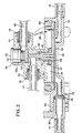
- headlight washer means 32 are mounted on the vehicle adjacent the headlights 28, and a fluid pressure piloted air relay valve 34, Figs. 1-3, of novel structure is capable of being tapped into the vehicle pressurized windshield washer system conduit 16 and also into the air pressurized system air-line 24 for using a combination of the windshield washer fluid and pressurized air to clean the headlights when the switch 22 is turned on to supply fluid to the windshield washers.
- the valve 34 comprises a valve body 36 with a central bore or cylinder 38 having the stem 40 of a diaphragm 42 slidably contained therein.
- An air inlet port 44 adjacent the opposite end of the stem 40 from the diaphragm leads into the bore 38 from one side thereof and an air outlet port 46 leads away from the bore on the opposite side.
- Outlet port 46 is axially offset from port 44.
- Ports 44 and 46 are adapted to receive conventional fittings 48 that connect hoses 45 and 47, respectively, into the valve body.
- Bore 38 has a counterbore 38a which is closed at the end opposite from the diaphragm by an end cap 50.
- Bore 38a has a sealing disc 52 disposed freely therein and held in airtight engagement with the inner end of the counterbore 38a by air pressure supplied by air inlet port 44 and by a compression spring 54.
- Diaphragm 42 operates in a chamber 56 in the valve body and is urged outwardly into abutment with a flexible backing cover 58 and a housing cover 60 by a conical compression spring 62.
- the stem 40 is of selected length so that the one end thereof is disposed closely adjacent the seal 52 but not engaging the seal during normal or rest position of the diaphragm against the housing cover 60.
- Compression spring 54 is of sufficient strength to hold the seal 52 in sealed engagement against the inner end of counterbore 38a and supplements the higher force of pressured air at inlet 44 but such forces are readily overcome by opposing forces of liquid acting on the large diaphragm, Fig. 3, as will be more apparent hereinafter. Unseating of the seal 52 allows pressurized movement of air through the valve.
- the valve housing cover 60 has a cleaning fluid inlet port 66 for a hose fitting 68 and connected inlet washer inlet hose 70 and an outlet port 72 capable of connection to an outlet hose 74.
- Inlet port 66 includes a filter 76 and a sealing O-ring 78.
- Valve body 36 and cover 60 are suitably secured together by a permanent lock ring 80.
- diaphragm 42 and backing cover 58 seal off any flow of liquid between the inlet port 66 and outlet port 72, including gravity flow of liquid.
- valve 34 is in communication with the headlight washer means 32 by air outlet hose 47 from the valve and by washer liquid outlet hose 74 from the valve.
- the washer means is mounted on a portion 84 of the vehicle that is adjacent to the headlight lens 86, or suitable bracketing can be supplied.
- the washer means 32 comprises a nozzle housing 88, also seen in Fig. 5, having a base plate 90 and a cover 92 therefor.
- the base plate and cover have sockets 94 and 94a for a washer fluid inlet fitting 96 for hose 74 from valve 34 and for an air fitting 98 for hose 47 from the valve.
- Cover 92 is internally contoured to fit in air sealed engagement with the inwardly projecting ends of the fittings 96 and 98 and downwardly against the base plate 90.
- Fastening means 100 secure the base plate 90 and cover 92 to the vehicle.
- Housing cover 92 includes a passageway 104 adjacent its front end that leads from the inner end of fitting socket 94a to an angled jet outlet port 106 exiting though the front of the housing.
- Housing 92 and base plate 90 also include a longitudinal passageway 108 that opens through the front of the housing in a jet outlet port 110 arranged to direct air straight out in intersecting relation with the cleaning fluid jet stream. Such intersecting relation is shown in Fig. 6 wherein the numerals 106a and 110a designate the jets from the cleaning fluid jet stream and the air stream, respectively.
- Air passageway 108 in the cover is in communication with the air socket 94a by auxiliary passageways 108a.
- Intersection of the cleaning fluid stream 106 by the air stream is a short distance in front of the nozzle housing 88 whereby the pressurized cleaning fluid jet will be broken up into a spray pattern 112 prior to hitting the lens.
- Positioning of the washer means 32 on the vehicle and the angle of the outlet port 106 is preselected such that the spray stream 112 is aimed at the headlight and preferably at a surface close to the washer.
- the spacing of the washer means 32 from the lens may vary somewhat depending upon the pressure that exists in the air system of the vehicle but an average spacing is from approximately 3-6 inches (7.6-15.2cm).
- the point of intersection of the jets from the nozzle housing is about one inch (2.5cm).
- the spray can be directed in an overall pattern at the headlight or even to a closest point on the headlight relative to the washer means since the spray pattern not only will hold the liquid on the lens but will cause it to spread and migrate in close contact across the lens for efficient cleaning.
- the present headlight washer system is tapped into the windshield wiper washer system for its liquid, namely, hose 70 which is associated with liquid inlet port 66 of the valve 34 and which is connected into line 16 of the existing windshield wiper washer system.
- the air for the present headlight washer system is received from the pressured air system on the vehicle, namely, hose 45 which is associated with air inlet port 44 of the valve is connected into the line 24 of the pressured system.
- the present headlight washer system is activated each time that the windshield wiper washer system is turned on as will now become apparent.
- the stem 40 of the diaphragm engages sealing disc 52, and the diaphragm also is arranged to overcome the spring 54 and air pressure in port 44, wherein pressured washer liquid flows between inlet and outlet ports 66 and 72, respectively, of the valve for the supply of the liquid to the headlight washer nozzle 32 by hose 74 and for supply of the air to the nozzle 32 through inlet and outlet ports 66 and 72, respectively, counterbore 38a and bore 38.
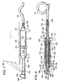
- Figs. 7 and 8 illustrate a second form of washer means 32'.
- This form of washer similar to the first embodiment, is mounted on a vehicle adjacent the headlight, Fig. 7.
- the embodiment of Fig. 7 has an extending nozzle portion that when activated moves from a retracted position to a spray position. It comprises an elongated cylinder housing 14 and an end cap extension 114a. The cylinder and end cap have mounting ears 116 thereon for securement to the vehicle in a manner to be described.
- a forward end of the cylinder housing 114a has an outlet port 118 comprising an escape outlet for cleaning fluid and debris.
- a rearward end portion of the cylinder housing 114 has an air inlet port 120 for connection to the hose 47 of the outlet port 46 of the valve.
- Cylinder housing 114 has a piston head 122 slidable therein having a central bore 123.
- This piston head has opposite end bosses 124 for securement thereto respectively of a rearwardly extending hollow piston rod 126 that projects through the rearward end of the housing and a forwardly extending hollow piston rod 128 that projects through the forward end of the housing.
- the rearward and forward ends of the piston rods have sealing engagement with the ends of the housing by O-rings 130.
- Housing portions 114 and 114a are held securely together by a surface clamp 134 and these housing portions are secured in a non-rotatable relative movement by one or more radial pins 136.
- the piston and piston rod assembly are held against rotation within the housing by a guide pin 138 mounted in a front portion of housing cap 114a and having a head portion 140 that projects into and rides in a longitudinal surface groove 142 in the forward piston rod 128.
- Piston 122 includes a sealing O-ring 146 disposed at a rearward portion of its surface and a wiping element 150 disposed in its surface forward of the O-ring. Wiping element 150 protects the O-ring from contaminants that may enter the cylinder from the front.
- the piston rod assembly has spring return by a compression spring 152. Spring return movement of the piston rod assembly is limited by a stop projection 154 on a forward portion of piston rod 128 engageable with the front of the housing cap 114a.
- a hose fitting 156 is secured at the rearward end of the piston rod 126 and attaches hose 74 from the outlet port 72 of the valve 34 with a flexible tube 158 extending through the piston rod assembly and terminating in a front exposed head 160 of the piston rod 128.
- This head includes a pair of bores 162 and 164. Bore 162 receives the tube from the piston rod 128 and bore 164 receives the terminal end of the tube 158 after the latter has been bent reversely around a rounded front end 166 of the head 160.
- the front terminal end of tube 158 comprises a jet opening 168 for cleaning fluid admitted from hose 74.
- Head 160 has a front end cap 169.
- Air inlet port 120 communicates with the interior of cylinder housing 114 and this port 120 also communicates with the interior of rear piston rod 126 by means of a port 170 in the wall of this piston rod.
- Hose 158 passes through the piston head 122 in a clearance fit wherein pressurized air from inlet port 120 has two functions, namely, to drive the piston rod assembly forwardly and also provide air pressure within the piston rod assembly. Forced air from within the piston rod assembly exits through a bore 172 adjacent the front of the piston rod 128.
- Bore 172 forms a jet opening for air and is preselected in position to intersect a cleaning fluid jet exiting through port 168.
- the pressurized jet of air breaks up the cleaning fluid jet and forms a spray that is arranged to impinge against the headlight for cleaning as follows.
- the hose 74 from the valve supplies pressurized cleaning fluid to tube 158 in the piston rod assembly and cleaning fluid is ejected forcefully from jet opening 168.
- pressurized air from hose 47 leading from air outlet port 46 enters the cylinder housing through inlet 120 behind the piston head 122 and drives the piston rod assembly from its retracted position of Fig.
- Air also reaches the jet opening 172 of piston rod 128 by escaping past the clearance fit of tube 158 as it passes through the piston head.
- the jet of air that intersects the jet of cleaning fluid breaks up the latter into a spray and forcefully drives it at an angle away from the nozzle.
- Outward movement of the piston rod assembly is controlled by a stop projection 176 adjacent the rearward end of the piston rod assembly and engageable with the adjacent end of the housing. The nozzle will be driven to its return or retracted position by the spring 152 as soon as the pressurized air is shut off.
- Fig. 7 illustrates a mounting position of the nozzle.
- a platform 174 is available or made available to hang the nozzle under it.
- the mounting is such that when retracted, the nozzle head is behind the outer end of the platform 174 for protection but when extended the nozzle end is positioned to direct the cleaning spray selectively against the headlight 28.
- the washer comprises a housing 180 which receives pressurized air via inlet 182 and fluid via opening 184.
- the fluid opening 184 extends inwardly of an annular cavity portion 186 as a tube like member 185, slightly off center of the cavity and is slidingly received within a bore 188 of a piston member 190, which suitably fits within and translates inwardly and outwardly of bore 186.
- Tube 185 terminates in an opening 192 which is in sealing engagement with bore 188 of piston 190 by use of an O-ring 194 near the distal end of tube 185, adjacent the opening 192.
- Piston 190 is suitably maintained in sealing engagement with bore 186 by O-ring 196.
- a spring member 198 surrounds piston 190 and is within a cavity which has a leak port 199 defined in the body of piston 190 so as to provide fluid communication between bore 200 of the piston and the annular space defined between the interior of housing 180 and the outer wall of piston 190.
- Air inlet 182 is also in fluid communication to bore 200.
- the end of spring 198 closest to the end of housing 180 where connections 182 and 184 are positioned rests against a flange portion of piston 190.
- the end of spring 198 which is distal from inlet 182 suitably engages against a flange portion of a cap 202 which fits over the open end of housing 180.
- the cap has a central annular bore therein which receives piston 190 therethrough and allows sliding movement of the piston 190 inwardly and outwardly of the housing 180 as may be observed by comparison of FIGS. 9 and 10.
- a rod wiper 204 is placed adjacent cap 202 near the opening thereof and is in surrounding engagement with piston 190, suitably removing contamination from the piston as it retracts into the housing.
- a washer or other securement member 206 maintains the rod wiper in position by preventing forward movement thereof as the piston rod 190 extends.
- piston 190 is covered by an end cap 208 which provides an angled fluid communication with chamber 200 and results in communication of air as provided through inlet 182 upwardly at an angle towards a headlight member in the direction of arrow 210 when air pressure is applied.
- the distal end of bore 188 is tapered to narrow somewhat and communicates with a bore 212 that extends substantially upwardly in perpendicular fashion.
- a sealing member 214 suitably comprising a chrome ball, blocks the open end of bore 188 beyond the opening 212.
- air pressure is provided through inlet 182 and causes piston 190 to extend as illustrated in FIG. 10.
- spring 198 is compressed whereupon when fully compressed, the spring acts as a stop such that engagement of the spring with the flange of cap 202 and the flange of the piston provides the hard stop.
- fluid inlet port 184 and exits through opening 192 of tube 185 it continues through bore 188 of the piston whereupon, since the fluid is blocked from further longitudinal travel by stopper 214, the fluid extends upwardly through bore 212 in the direction of arrow 216.
- the air stream 210 is oriented at an angle and collides with the upwardly extending fluid stream 216 so as to generate a suitably fan-shaped fluid spray 218 upwardly towards the headlight of the vehicle.
- the air pressure and fluid pressure are cut off whereupon the spring 198 will cause piston 190 to retract and piston rod wiper 204 will clean off any dirt or the like on the piston rod to prevent entry thereof into the portion of the housing containing the spring.
- the opening 199 provides fluid communication between the area of the housing containing the spring and bore 200, such that during the extension stroke of the piston, air within the chamber surrounding the spring is not compressed, but instead is allowed to vent into bore 200.
- the end cap 208 suitably clips to or is otherwise secured to the end of the piston such that it may be easily replaced or removed if necessary for any reason.
- a headlight lens cleaning system is provided that is simplified in structure and operation. It can be applied to any vehicle having pressurised air on board and a pressurised windshield wiper washer system. It is activated by turning on the windshield wiper washers. Such system simultaneously activates the windshield wiper blade washers and the headlight lens washers for simplicity of washer fluid means, pressurising means and electrical circuitry.
Landscapes
- Engineering & Computer Science (AREA)
- Mechanical Engineering (AREA)
- Water Supply & Treatment (AREA)
- Nozzles (AREA)
- Lighting Device Outwards From Vehicle And Optical Signal (AREA)
- Non-Portable Lighting Devices Or Systems Thereof (AREA)
- Cleaning By Liquid Or Steam (AREA)
- Air-Conditioning For Vehicles (AREA)
- Arrangement Of Elements, Cooling, Sealing, Or The Like Of Lighting Devices (AREA)
Abstract
Description
Claims (12)
- An air-liquid headlight cleaning system for vehicles of the type which have pressurised air on board and also a manual activated pressurised washer system (16) for windshield wipers having a reservoir (18), said cleaning system comprising: a liquid outlet nozzle (106); an air outlet nozzle (110); and a valve (34) capable of connection in the pressurised air on a vehicle and in the pressurised washer system for the windshield wipers (14), wherein to automatically direct liquid from the pressurised washer system of the vehicle and air from the pressurised air on board the vehicle to said liquid and air outlets (106, 100) to form a headlight cleaning function upon manual activation of the pressurised washer system of the vehicle; characterised by: means (32) associated with said liquid outlet nozzle capable of mounting said liquid outlet nozzle on a vehicle in a position such that a jet of cleaning fluid from said liquid outlet nozzle is directed outward in the area of the headlight of the vehicle; and means (32) associated with said air outlet nozzle capable of mounting said air outlet nozzle on a vehicle in a position such that said jet of air from said air outlet nozzle intersects said jet of cleaning liquid and forms a spray mixture that is directed toward a headlight of the vehicle.
- A headlight cleaning system according to claim 1 characterised in that said valve (34) includes plunger means arranged normally to shut off gravity flow of liquid to said liquid outlet nozzle (106) and pressurised air flow to said air outlet nozzle (110) but to allow pressurised liquid flow to said liquid outlet nozzle (106) and air flow to said air outlet nozzle (110) upon being exposed to liquid pressure from the pressurised washer system.
- A headlight cleaning system according to claim 1 characterised by support means capable of mounting said liquid and air outlet nozzles (106, 110) on a vehicle in angular disposition to a headlight lens (28), said nozzles (106, 110) being angularly disposed relative to each other such that the jets from the pressurised liquid outlet and pressurised air outlet intersect at a point prior to impinging against the headlight lens (28) for forming said spray.
- A headlight cleaning system according to claim 3 characterised in that the point at which the jets from said liquid and air outlets intersect is approximately 3 inches (7.6cm) from the headlight lens (28).
- A headlight cleaning system according to claim 3 characterised in that one of said liquid outlet nozzle (106) and air outlet nozzle (110) is aimed toward the headlight lens (28) and the other of said nozzles is aimed in angular relation to said one of said nozzles such that the jets intersect to cause the jet of cleaning liquid to be broken up into a spray that is driven into the headlight lens by the jet of air.
- A headlight cleaning system according to claim 5 characterised by a nozzle housing (88, 114) that supports both of said liquid outlet and air outlet nozzles (106, 110) together in their angular relation.
- A headlight cleaning system according to claim 6 characterised in that said nozzle housing (114) includes piston operating means that extend said liquid and air outlets outwardly of said housing upon activation of said cleaning system.
- A headlight cleaning system according to claim 1 characterised in that said valve includes a housing having an internal chamber (56), a diaphragm (42) in said chamber (56) having a stem (40) slidable in said housing, washer fluid inlet means in said housing, capable of communication with the pressurised washer system of the vehicle and washer fluid outlet means communicating with said liquid outlet nozzle, sealing means (52) in said housing associated with said diaphragm (42) for controlling flow between said washer fluid inlet means and said washer fluid outlet means, air inlet means in said housing capable of communication with the pressurised air on the vehicle and air outlet means communicating with said air outlet nozzle (110), and sealing means (52) in said housing between said air inlet and air outlet means capable of being unseated by said stem (40) upon slidable movement of the latter in said housing as a result of force being applied to said diaphragm (42) from the pressure washer system.
- A headlight cleaning system according to claim 1 characterised in that the liquid outlet nozzle (106) and the air outlet nozzle (110) are mountable adjacent to the headlight (28) of a vehicle; and the system further comprises a nozzle housing (114); means on said housing supporting the liquid outlet nozzle (168) and the air outlet nozzle (172); means on said nozzle housing capable of mounting said housing on a vehicle in a position adjacent to the headlight (28) of the vehicle; and drive means in said housing (114) capable of extending said liquid and air outlets (168, 172) outwardly upon activation of said cleaning system.
- A headlight cleaning system according to claim 9 characterised in that said drive means includes a piston (122) operable by the pressurised air on board the vehicle upon activation of the headlight cleaning system.
- A headlight cleaning system according to claim 9 characterised in that said liquid outlet nozzle (106) and said air outlet nozzle (110) are defined on an extensible member (128), wherein upon application of air from the pressurised air on board the vehicle system, said extensible member will extend to a cleaning position.
- A headlight cleaning system according to claim 11 further characterised by biasing means (152) for urging said extensible member (128) to a retracted position upon removal of air from the pressurised air system on board said vehicle system.
Applications Claiming Priority (5)
| Application Number | Priority Date | Filing Date | Title |
|---|---|---|---|
| US50845595A | 1995-07-28 | 1995-07-28 | |
| US508455 | 1995-07-28 | ||
| US08/583,343 US5657929A (en) | 1995-07-28 | 1996-01-05 | Air-liquid system for cleaning vehicle headlight lens and similar surfaces |
| US583343 | 1996-01-05 | ||
| PCT/US1996/012467 WO1997004875A1 (en) | 1995-07-28 | 1996-07-29 | Air-liquid system for cleaning vehicle headlight lens and similar surfaces |
Publications (3)
| Publication Number | Publication Date |
|---|---|
| EP0848650A1 EP0848650A1 (en) | 1998-06-24 |
| EP0848650A4 EP0848650A4 (en) | 2001-08-29 |
| EP0848650B1 true EP0848650B1 (en) | 2003-09-24 |
Family
ID=27056197
Family Applications (1)
| Application Number | Title | Priority Date | Filing Date |
|---|---|---|---|
| EP96926185A Expired - Lifetime EP0848650B1 (en) | 1995-07-28 | 1996-07-29 | Air-liquid system for cleaning vehicle headlight lens and similar surfaces |
Country Status (8)
| Country | Link |
|---|---|
| US (1) | US5657929A (en) |
| EP (1) | EP0848650B1 (en) |
| AT (1) | ATE250463T1 (en) |
| DE (1) | DE69630134T2 (en) |
| DK (1) | DK0848650T3 (en) |
| ES (1) | ES2205050T3 (en) |
| MX (1) | MX9800766A (en) |
| WO (1) | WO1997004875A1 (en) |
Families Citing this family (52)
| Publication number | Priority date | Publication date | Assignee | Title |
|---|---|---|---|---|
| DE19746275B4 (en) * | 1997-10-20 | 2005-12-15 | Siemens Ag | Cleaning device for a window of a motor vehicle |
| DE19748447A1 (en) * | 1997-11-03 | 1999-05-06 | Mannesmann Vdo Ag | Spray nozzle movable by an actuator |
| US6199773B1 (en) | 1999-06-11 | 2001-03-13 | Commercial Vehicle Systems, Inc. | Fluid and air nozzle for headlight cleaning |
| US6554210B2 (en) * | 1999-06-11 | 2003-04-29 | Commercial Vehicle Systems, Inc. | Fluid and air nozzle and method for cleaning vehicle lenses |
| DE10012004A1 (en) * | 2000-03-11 | 2001-09-27 | Bosch Gmbh Robert | Cleaning device for automobile optical element, such as glass cover disc for camera, directs cleaning gas stream across surface of optical element for preventing deposition of dirt |
| DE10016588B4 (en) * | 2000-04-04 | 2005-07-28 | Automotive Lighting Reutlingen Gmbh | Telescopic spray nozzle for a headlight cleaning system |
| GB0012356D0 (en) * | 2000-05-22 | 2000-07-12 | Textron Automotive Company Lim | Fluid spray nozzle |
| DE10125898B4 (en) * | 2000-05-31 | 2004-08-19 | Asmo Co., Ltd., Kosai | nozzle |
| JP3626077B2 (en) * | 2000-06-27 | 2005-03-02 | 株式会社小糸製作所 | Headlamp cleaner |
| DE20021641U1 (en) * | 2000-12-20 | 2001-02-22 | Reitter & Schefenacker GmbH & Co. KG, 73730 Esslingen | Cleaning device for vehicles, preferably motor vehicles |
| JP3857563B2 (en) * | 2001-08-24 | 2006-12-13 | アスモ株式会社 | Vehicle washer system |
| US6951223B2 (en) * | 2001-10-17 | 2005-10-04 | Asmo Co., Ltd. | Cleaning liquid supply system having pumps connected to tank |
| DE10307476A1 (en) * | 2003-02-21 | 2004-09-09 | Bayerische Motoren Werke Ag | aerator |
| JP2004298778A (en) * | 2003-03-31 | 2004-10-28 | Asmo Co Ltd | Washer nozzle and hose joint |
| DE10342715B4 (en) * | 2003-09-16 | 2006-09-21 | Bayerische Motoren Werke Ag | Windscreen washer system for a motor vehicle |
| US7584521B2 (en) * | 2005-12-21 | 2009-09-08 | Itt Manufacturing Enterprises, Inc. | Dust mitigation and surface cleaning system for maintaining a surface free from dust and other materials |
| DE102007002810A1 (en) * | 2007-01-18 | 2008-07-24 | Hella Kgaa Hueck & Co. | Windscreen cleaning device, particularly for vehicle headlights, has housing with nozzle carrier axially displaceable in working position from housing by pressure exerting cleaning fluid telescopically from initial position within housing |
| US8087122B2 (en) * | 2007-06-27 | 2012-01-03 | Keith Martin | Cleaning systems and methods for removing foreign substances from visible surfaces on vehicles |
| WO2009060413A2 (en) * | 2007-11-09 | 2009-05-14 | Fioravanti S.R.L. | An automobile vehicle with a wiperless cleaning system for glazed surfaces and the like |
| CA2672388C (en) | 2009-07-28 | 2017-02-21 | Craig Mcconnell | Method and apparatus for preventing a build up of snow or dust |
| US9156066B2 (en) * | 2011-08-29 | 2015-10-13 | Raytheon Company | Aperture cleaning system and methods of use |
| BR112015000243B1 (en) * | 2012-07-11 | 2021-07-13 | Nissan Motor Co., Ltd | CLEANING DEVICE FOR VEHICLE MOUNTED CAMERA AND METHOD OF CLEANING VEHICLE MOUNTED CAMERA |
| US9701173B2 (en) * | 2013-04-12 | 2017-07-11 | Ford Global Technologies, Llc | Method and apparatus for the reduction of washer fluid odor in the passenger compartment of a vehicle |
| JP6257341B2 (en) * | 2014-01-16 | 2018-01-10 | 株式会社ミツバ | NOZZLE, MANUFACTURING METHOD THEREOF, AND WASHER NOZZLE |
| DE102014220573A1 (en) * | 2014-10-10 | 2016-04-14 | Continental Teves Ag & Co. Ohg | Cleaning device for cleaning a transparent cover of a camera |
| CA2924557C (en) | 2015-04-13 | 2019-07-23 | Roderick Jones | Vehicular lamp cleaning system |
| FR3039113B1 (en) * | 2015-07-22 | 2017-07-28 | Valeo Systemes Dessuyage | DEVICE FOR CLEANING A SENSOR FOR A MOTOR VEHICLE |
| FR3039114B1 (en) * | 2015-07-22 | 2017-07-28 | Valeo Systemes Dessuyage | DEVICE FOR CLEANING A SENSOR FOR A MOTOR VEHICLE |
| WO2017169140A1 (en) * | 2016-03-31 | 2017-10-05 | アスモ 株式会社 | Onboard optical sensor cleaning device |
| FR3051752B1 (en) * | 2016-05-27 | 2018-06-15 | Valeo Systemes D'essuyage | SYSTEM FOR CLEANING AN OPTICAL SENSOR, AN ASSEMBLY COMPRISING SUCH A SYSTEM AND AN ASSOCIATED MOTOR VEHICLE |
| JP6766529B2 (en) * | 2016-08-31 | 2020-10-14 | 株式会社デンソー | In-vehicle optical sensor cleaning device |
| JP6702093B2 (en) * | 2016-08-31 | 2020-05-27 | 株式会社デンソー | In-vehicle optical sensor cleaning device |
| FR3056515B1 (en) * | 2016-09-28 | 2019-07-12 | Valeo Systemes D'essuyage | DEVICE FOR CLEANING AN OUTER SURFACE OF A SENSOR OF A MOTOR VEHICLE |
| FR3056516B1 (en) * | 2016-09-28 | 2022-12-30 | Valeo Systemes Dessuyage | CLEANING DEVICE INTENDED TO SPRAY AT LEAST ONE FLUID TOWARDS A SURFACE TO BE CLEANED OF A MOTOR VEHICLE |
| EP3318452A1 (en) * | 2016-11-07 | 2018-05-09 | Fico Transpar, S.A. | Fluid-ejection device |
| JP6537563B2 (en) * | 2017-06-28 | 2019-07-03 | 本田技研工業株式会社 | Cleaning unit |
| FR3082481B1 (en) * | 2018-06-14 | 2021-04-30 | Valeo Systemes Dessuyage | TELESCOPIC CLEANING DEVICE FOR MOTOR VEHICLES |
| US10960854B2 (en) * | 2018-08-03 | 2021-03-30 | Maric Ltd. | System for washing motor vehicle headlights |
| DE102018126091A1 (en) * | 2018-10-19 | 2020-04-23 | Wabco Gmbh | Cleaning device, compressed air system, vehicle and cleaning process |
| DE102018220582A1 (en) * | 2018-11-29 | 2020-06-04 | Continental Automotive Gmbh | Cleaning device with a reciprocating piston |
| JP7277198B2 (en) * | 2019-03-26 | 2023-05-18 | フォルシアクラリオン・エレクトロニクス株式会社 | Cleaning nozzle unit and in-vehicle camera unit |
| DE102019111468A1 (en) * | 2019-05-03 | 2020-11-05 | Wabco Gmbh | Cleaning device, compressed air system and cleaning method for applying a medium pulse to a surface as well as the corresponding control system and vehicle |
| EP3741632B1 (en) * | 2019-05-21 | 2023-09-06 | Fico Transpar, S.A. | Device and method for washing a surface of a motor vehicle part and fluid control valve for such device |
| US11453018B2 (en) | 2019-06-17 | 2022-09-27 | Ford Global Technologies, Llc | Sensor assembly with movable nozzle |
| US11279325B2 (en) * | 2019-06-24 | 2022-03-22 | Ford Global Technologies, Llc | Sensor cleaning |
| KR102260813B1 (en) * | 2019-11-14 | 2021-06-07 | 주식회사 니프코코리아 | Automotive Composite Nozzle |
| EP4196374B1 (en) * | 2020-08-14 | 2024-09-18 | ZF CV Systems Global GmbH | Cleaning device, cleaning device system and vehicle with a sensoric system comprising at least a sensor for automated driving and method of spray cleaning of a sensor surface with the cleaning device |
| US11921208B2 (en) * | 2020-08-27 | 2024-03-05 | Ford Global Technologies, Llc | Sensor apparatus with cleaning |
| US11654867B2 (en) * | 2020-11-30 | 2023-05-23 | A. Raymond Et Cie | Nozzle assembly for cleaning a vehicle surface |
| FR3121104A1 (en) * | 2021-03-23 | 2022-09-30 | Valeo Systemes D'essuyage | Device for cleaning a sensing surface of a sensing device. |
| DE102021210085A1 (en) * | 2021-09-13 | 2023-03-16 | Continental Automotive Technologies GmbH | Combined cleaning device for a sensor device of a vehicle |
| EP4286226A1 (en) * | 2022-06-01 | 2023-12-06 | ZKW Group GmbH | Air cleaning device |
Family Cites Families (23)
| Publication number | Priority date | Publication date | Assignee | Title |
|---|---|---|---|---|
| US3114168A (en) * | 1962-02-27 | 1963-12-17 | Taylor S Blackwell | Hydraulic windshield wiper and washer |
| US3453049A (en) * | 1965-10-21 | 1969-07-01 | Robert H Wager Co Inc | Lens cleaning system |
| US3456278A (en) * | 1966-04-14 | 1969-07-22 | Mccord Corp | Vehicle headlight clearing system |
| US3469088A (en) | 1966-05-18 | 1969-09-23 | Ford Motor Co | Apparatus for cleaning the lens of a vehicle running light |
| US3448481A (en) * | 1967-02-16 | 1969-06-10 | Gen Motors Corp | Fluid pressure operated windshield wiper system |
| US3496804A (en) * | 1968-04-10 | 1970-02-24 | Russell A Heitzman | Bandsaw automatic swaging apparatus |
| US3641613A (en) * | 1969-12-04 | 1972-02-15 | Chrysler Corp | Vehicular headlamp cleaner |
| US3893203A (en) * | 1971-12-22 | 1975-07-08 | Hans Berkelius | Drive motor for cleaning glass surfaces |
| DE2502389A1 (en) * | 1975-01-22 | 1976-07-29 | Wolfgang Reichert | Vehicle headlamp cleaning mechanism - has air inlet cowling in front of headlamps with washing spray injected in airflow |
| US3915385A (en) * | 1975-03-13 | 1975-10-28 | Donald F Hassinger | Vehicle headlamp washing system |
| US4026468A (en) * | 1975-08-14 | 1977-05-31 | Mccord Corporation | Headlamp cleaning assembly |
| US4026473A (en) * | 1975-10-20 | 1977-05-31 | Mccord Corporation | Headlamp cleaning assembly |
| US4230276A (en) * | 1976-07-27 | 1980-10-28 | Mccord Corporation | Headlamp cleaning assembly |
| DE2707310A1 (en) * | 1977-02-19 | 1978-08-24 | Arnold Engel | Vehicle windscreen cleaning system - uses low volume water spray spread over surface by compressed air jets |
| US4324363A (en) * | 1978-09-11 | 1982-04-13 | C-D Marketing Ltd. | Headlamp washer assembly having a multiported flow valve |
| JPS5639942A (en) * | 1979-09-06 | 1981-04-15 | Mitsubishi Electric Corp | Automatic elimination of water drop and dust from window of moving car |
| US4323266A (en) * | 1981-02-13 | 1982-04-06 | General Motors Corporation | Motor vehicle priority control system for operating leveling and washing systems from a single source of compressed air |
| FR2605906B1 (en) * | 1986-10-29 | 1989-04-28 | Peugeot | TELESCOPIC PROJECTOR WASHER FOR VEHICLE |
| US4815634A (en) * | 1987-03-27 | 1989-03-28 | Dema Engineering Co. | Vacuum actuated pump |
| JPS63279953A (en) * | 1987-05-11 | 1988-11-17 | Nec Corp | Compressed air injecting type wiper structure |
| IT1211611B (en) * | 1987-12-21 | 1989-11-03 | Siem Srl | WASHING DEVICE FOR FRONT LENSES OF LIGHTING EQUIPMENT PARTICULARLY MOTOR VEHICLE PROJECTORS |
| US5083339A (en) * | 1989-11-01 | 1992-01-28 | Sprague Aristo-Aire, Inc. | Apparatus for cleaning headlight lens and similar surfaces |
| US5546630A (en) * | 1995-01-04 | 1996-08-20 | Long; Andre | Blast wiper for motor vehicle lights |
-
1996
- 1996-01-05 US US08/583,343 patent/US5657929A/en not_active Expired - Lifetime
- 1996-07-29 EP EP96926185A patent/EP0848650B1/en not_active Expired - Lifetime
- 1996-07-29 AT AT96926185T patent/ATE250463T1/en not_active IP Right Cessation
- 1996-07-29 ES ES96926185T patent/ES2205050T3/en not_active Expired - Lifetime
- 1996-07-29 WO PCT/US1996/012467 patent/WO1997004875A1/en active IP Right Grant
- 1996-07-29 DE DE69630134T patent/DE69630134T2/en not_active Expired - Fee Related
- 1996-07-29 DK DK96926185T patent/DK0848650T3/en active
-
1998
- 1998-01-27 MX MX9800766A patent/MX9800766A/en unknown
Also Published As
| Publication number | Publication date |
|---|---|
| US5657929A (en) | 1997-08-19 |
| ES2205050T3 (en) | 2004-05-01 |
| MX9800766A (en) | 1998-10-31 |
| DE69630134T2 (en) | 2004-07-22 |
| ATE250463T1 (en) | 2003-10-15 |
| DK0848650T3 (en) | 2004-02-09 |
| DE69630134D1 (en) | 2003-10-30 |
| WO1997004875A1 (en) | 1997-02-13 |
| EP0848650A4 (en) | 2001-08-29 |
| EP0848650A1 (en) | 1998-06-24 |
Similar Documents
| Publication | Publication Date | Title |
|---|---|---|
| EP0848650B1 (en) | Air-liquid system for cleaning vehicle headlight lens and similar surfaces | |
| US6554210B2 (en) | Fluid and air nozzle and method for cleaning vehicle lenses | |
| US3915385A (en) | Vehicle headlamp washing system | |
| US20010054655A1 (en) | Cleaning device | |
| US7111355B1 (en) | Dual mode windshield wiper assembly | |
| EP0572147A1 (en) | Washing system for motor vehicle screens | |
| DE59500787D1 (en) | Nozzle holder for a windscreen washer system for vehicles, in particular vehicle headlights | |
| EP2274185B1 (en) | Light cleaning device | |
| JP2003532511A (en) | Liquid and air nozzles for cleaning headlights | |
| EP1252048B1 (en) | Concealed vehicular washer nozzle system | |
| US20020162580A1 (en) | Motion wheel washer | |
| CA2227199C (en) | Air-liquid system for cleaning vehicle headlight lens and similar surfaces | |
| US3089204A (en) | Windshield washer apparatus for vehicles | |
| US2714739A (en) | Nozzle assembly for vehicle windshield clearing systems | |
| US20240067133A1 (en) | Method for a retrofitting of a vehicle, method for an operation, cleaning apparatus, retrofitting system, kit, and vehicle | |
| KR200144782Y1 (en) | Rear view mirror for passenger car with rainwater removal device | |
| JP2003011790A (en) | Lamp cleaner system | |
| CN113734101A (en) | Water sprayer, automobile wiper and automobile comprising same | |
| GB2289427A (en) | Self-cleaning nozzle having pin actuated by fluid flow | |
| KR0177087B1 (en) | Windshield washer nozzle housing device | |
| KR100194193B1 (en) | Drip remover for car rearview mirror | |
| KR200312956Y1 (en) | Apparatus for cleaning side window and side mirror of automobile | |
| KR100219088B1 (en) | Head lamp washer device of an automobile | |
| KR19980039241U (en) | Wind washer injection structure of car | |
| KR19980051484U (en) | Washer liquid injection nozzle unit |
Legal Events
| Date | Code | Title | Description |
|---|---|---|---|
| PUAI | Public reference made under article 153(3) epc to a published international application that has entered the european phase |
Free format text: ORIGINAL CODE: 0009012 |
|
| 17P | Request for examination filed |
Effective date: 19980220 |
|
| AK | Designated contracting states |
Kind code of ref document: A1 Designated state(s): AT BE CH DE DK ES FI FR GB IT LI NL SE |
|
| RAP1 | Party data changed (applicant data changed or rights of an application transferred) |
Owner name: COMMERCIAL VEHICLE SYSTEMS, INC. |
|
| A4 | Supplementary search report drawn up and despatched |
Effective date: 20010718 |
|
| AK | Designated contracting states |
Kind code of ref document: A4 Designated state(s): AT BE CH DE DK ES FI FR GB IT LI NL SE |
|
| 17Q | First examination report despatched |
Effective date: 20020122 |
|
| GRAH | Despatch of communication of intention to grant a patent |
Free format text: ORIGINAL CODE: EPIDOS IGRA |
|
| GRAH | Despatch of communication of intention to grant a patent |
Free format text: ORIGINAL CODE: EPIDOS IGRA |
|
| GRAA | (expected) grant |
Free format text: ORIGINAL CODE: 0009210 |
|
| AK | Designated contracting states |
Kind code of ref document: B1 Designated state(s): AT BE CH DE DK ES FI FR GB IT LI NL SE |
|
| REG | Reference to a national code |
Ref country code: GB Ref legal event code: FG4D |
|
| REG | Reference to a national code |
Ref country code: CH Ref legal event code: EP |
|
| REF | Corresponds to: |
Ref document number: 69630134 Country of ref document: DE Date of ref document: 20031030 Kind code of ref document: P |
|
| REG | Reference to a national code |
Ref country code: CH Ref legal event code: NV Representative=s name: MOINAS & SAVOYE SA |
|
| REG | Reference to a national code |
Ref country code: SE Ref legal event code: TRGR |
|
| REG | Reference to a national code |
Ref country code: DK Ref legal event code: T3 |
|
| REG | Reference to a national code |
Ref country code: ES Ref legal event code: FG2A Ref document number: 2205050 Country of ref document: ES Kind code of ref document: T3 |
|
| ET | Fr: translation filed | ||
| PGFP | Annual fee paid to national office [announced via postgrant information from national office to epo] |
Ref country code: GB Payment date: 20040709 Year of fee payment: 9 |
|
| PGFP | Annual fee paid to national office [announced via postgrant information from national office to epo] |
Ref country code: NL Payment date: 20040722 Year of fee payment: 9 |
|
| PGFP | Annual fee paid to national office [announced via postgrant information from national office to epo] |
Ref country code: FR Payment date: 20040723 Year of fee payment: 9 |
|
| PGFP | Annual fee paid to national office [announced via postgrant information from national office to epo] |
Ref country code: AT Payment date: 20040726 Year of fee payment: 9 |
|
| PGFP | Annual fee paid to national office [announced via postgrant information from national office to epo] |
Ref country code: SE Payment date: 20040727 Year of fee payment: 9 Ref country code: DE Payment date: 20040727 Year of fee payment: 9 |
|
| PGFP | Annual fee paid to national office [announced via postgrant information from national office to epo] |
Ref country code: FI Payment date: 20040729 Year of fee payment: 9 Ref country code: ES Payment date: 20040729 Year of fee payment: 9 Ref country code: DK Payment date: 20040729 Year of fee payment: 9 |
|
| PLBE | No opposition filed within time limit |
Free format text: ORIGINAL CODE: 0009261 |
|
| STAA | Information on the status of an ep patent application or granted ep patent |
Free format text: STATUS: NO OPPOSITION FILED WITHIN TIME LIMIT |
|
| PGFP | Annual fee paid to national office [announced via postgrant information from national office to epo] |
Ref country code: CH Payment date: 20040804 Year of fee payment: 9 |
|
| PGFP | Annual fee paid to national office [announced via postgrant information from national office to epo] |
Ref country code: BE Payment date: 20040901 Year of fee payment: 9 |
|
| 26N | No opposition filed |
Effective date: 20040625 |
|
| PG25 | Lapsed in a contracting state [announced via postgrant information from national office to epo] |
Ref country code: FI Free format text: LAPSE BECAUSE OF NON-PAYMENT OF DUE FEES Effective date: 20050710 |
|
| PG25 | Lapsed in a contracting state [announced via postgrant information from national office to epo] |
Ref country code: IT Free format text: LAPSE BECAUSE OF NON-PAYMENT OF DUE FEES;WARNING: LAPSES OF ITALIAN PATENTS WITH EFFECTIVE DATE BEFORE 2007 MAY HAVE OCCURRED AT ANY TIME BEFORE 2007. THE CORRECT EFFECTIVE DATE MAY BE DIFFERENT FROM THE ONE RECORDED. Effective date: 20050729 Ref country code: GB Free format text: LAPSE BECAUSE OF NON-PAYMENT OF DUE FEES Effective date: 20050729 Ref country code: AT Free format text: LAPSE BECAUSE OF NON-PAYMENT OF DUE FEES Effective date: 20050729 |
|
| PG25 | Lapsed in a contracting state [announced via postgrant information from national office to epo] |
Ref country code: SE Free format text: LAPSE BECAUSE OF NON-PAYMENT OF DUE FEES Effective date: 20050730 Ref country code: ES Free format text: LAPSE BECAUSE OF NON-PAYMENT OF DUE FEES Effective date: 20050730 |
|
| PG25 | Lapsed in a contracting state [announced via postgrant information from national office to epo] |
Ref country code: LI Free format text: LAPSE BECAUSE OF NON-PAYMENT OF DUE FEES Effective date: 20050731 Ref country code: CH Free format text: LAPSE BECAUSE OF NON-PAYMENT OF DUE FEES Effective date: 20050731 Ref country code: BE Free format text: LAPSE BECAUSE OF NON-PAYMENT OF DUE FEES Effective date: 20050731 |
|
| PG25 | Lapsed in a contracting state [announced via postgrant information from national office to epo] |
Ref country code: DK Free format text: LAPSE BECAUSE OF NON-PAYMENT OF DUE FEES Effective date: 20050801 |
|
| PG25 | Lapsed in a contracting state [announced via postgrant information from national office to epo] |
Ref country code: NL Free format text: LAPSE BECAUSE OF NON-PAYMENT OF DUE FEES Effective date: 20060201 Ref country code: DE Free format text: LAPSE BECAUSE OF NON-PAYMENT OF DUE FEES Effective date: 20060201 |
|
| REG | Reference to a national code |
Ref country code: CH Ref legal event code: PL |
|
| EUG | Se: european patent has lapsed | ||
| GBPC | Gb: european patent ceased through non-payment of renewal fee |
Effective date: 20050729 |
|
| PG25 | Lapsed in a contracting state [announced via postgrant information from national office to epo] |
Ref country code: FR Free format text: LAPSE BECAUSE OF NON-PAYMENT OF DUE FEES Effective date: 20060331 |
|
| NLV4 | Nl: lapsed or anulled due to non-payment of the annual fee |
Effective date: 20060201 |
|
| REG | Reference to a national code |
Ref country code: DK Ref legal event code: EBP |
|
| REG | Reference to a national code |
Ref country code: FR Ref legal event code: ST Effective date: 20060331 |
|
| REG | Reference to a national code |
Ref country code: ES Ref legal event code: FD2A Effective date: 20050730 |
|
| BERE | Be: lapsed |
Owner name: *COMMERCIAL VEHICLE SYSTEMS INC. Effective date: 20050731 |