EP0848583A1 - Display device - Google Patents
Display device Download PDFInfo
- Publication number
- EP0848583A1 EP0848583A1 EP97117125A EP97117125A EP0848583A1 EP 0848583 A1 EP0848583 A1 EP 0848583A1 EP 97117125 A EP97117125 A EP 97117125A EP 97117125 A EP97117125 A EP 97117125A EP 0848583 A1 EP0848583 A1 EP 0848583A1
- Authority
- EP
- European Patent Office
- Prior art keywords
- substrate
- display device
- perforation
- strips
- starting substrate
- Prior art date
- Legal status (The legal status is an assumption and is not a legal conclusion. Google has not performed a legal analysis and makes no representation as to the accuracy of the status listed.)
- Granted
Links
Images

Classifications
-
- H—ELECTRICITY
- H05—ELECTRIC TECHNIQUES NOT OTHERWISE PROVIDED FOR
- H05K—PRINTED CIRCUITS; CASINGS OR CONSTRUCTIONAL DETAILS OF ELECTRIC APPARATUS; MANUFACTURE OF ASSEMBLAGES OF ELECTRICAL COMPONENTS
- H05K1/00—Printed circuits
- H05K1/02—Details
- H05K1/11—Printed elements for providing electric connections to or between printed circuits
- H05K1/118—Printed elements for providing electric connections to or between printed circuits specially for flexible printed circuits, e.g. using folded portions
-
- H—ELECTRICITY
- H05—ELECTRIC TECHNIQUES NOT OTHERWISE PROVIDED FOR
- H05K—PRINTED CIRCUITS; CASINGS OR CONSTRUCTIONAL DETAILS OF ELECTRIC APPARATUS; MANUFACTURE OF ASSEMBLAGES OF ELECTRICAL COMPONENTS
- H05K1/00—Printed circuits
- H05K1/18—Printed circuits structurally associated with non-printed electric components
- H05K1/189—Printed circuits structurally associated with non-printed electric components characterised by the use of a flexible or folded printed circuit
-
- H—ELECTRICITY
- H05—ELECTRIC TECHNIQUES NOT OTHERWISE PROVIDED FOR
- H05K—PRINTED CIRCUITS; CASINGS OR CONSTRUCTIONAL DETAILS OF ELECTRIC APPARATUS; MANUFACTURE OF ASSEMBLAGES OF ELECTRICAL COMPONENTS
- H05K2201/00—Indexing scheme relating to printed circuits covered by H05K1/00
- H05K2201/05—Flexible printed circuits [FPCs]
- H05K2201/053—Tails
-
- H—ELECTRICITY
- H05—ELECTRIC TECHNIQUES NOT OTHERWISE PROVIDED FOR
- H05K—PRINTED CIRCUITS; CASINGS OR CONSTRUCTIONAL DETAILS OF ELECTRIC APPARATUS; MANUFACTURE OF ASSEMBLAGES OF ELECTRICAL COMPONENTS
- H05K2201/00—Indexing scheme relating to printed circuits covered by H05K1/00
- H05K2201/09—Shape and layout
- H05K2201/09009—Substrate related
- H05K2201/0909—Preformed cutting or breaking line
-
- H—ELECTRICITY
- H05—ELECTRIC TECHNIQUES NOT OTHERWISE PROVIDED FOR
- H05K—PRINTED CIRCUITS; CASINGS OR CONSTRUCTIONAL DETAILS OF ELECTRIC APPARATUS; MANUFACTURE OF ASSEMBLAGES OF ELECTRICAL COMPONENTS
- H05K2201/00—Indexing scheme relating to printed circuits covered by H05K1/00
- H05K2201/10—Details of components or other objects attached to or integrated in a printed circuit board
- H05K2201/10007—Types of components
- H05K2201/10106—Light emitting diode [LED]
-
- H—ELECTRICITY
- H05—ELECTRIC TECHNIQUES NOT OTHERWISE PROVIDED FOR
- H05K—PRINTED CIRCUITS; CASINGS OR CONSTRUCTIONAL DETAILS OF ELECTRIC APPARATUS; MANUFACTURE OF ASSEMBLAGES OF ELECTRICAL COMPONENTS
- H05K2201/00—Indexing scheme relating to printed circuits covered by H05K1/00
- H05K2201/10—Details of components or other objects attached to or integrated in a printed circuit board
- H05K2201/10007—Types of components
- H05K2201/10128—Display
-
- H—ELECTRICITY
- H05—ELECTRIC TECHNIQUES NOT OTHERWISE PROVIDED FOR
- H05K—PRINTED CIRCUITS; CASINGS OR CONSTRUCTIONAL DETAILS OF ELECTRIC APPARATUS; MANUFACTURE OF ASSEMBLAGES OF ELECTRICAL COMPONENTS
- H05K3/00—Apparatus or processes for manufacturing printed circuits
- H05K3/0011—Working of insulating substrates or insulating layers
- H05K3/0044—Mechanical working of the substrate, e.g. drilling or punching
- H05K3/0052—Depaneling, i.e. dividing a panel into circuit boards; Working of the edges of circuit boards
Definitions
- the invention relates to a display device, especially for a motor vehicle, with at least a component arranged on a substrate.
- Combination instruments in particular for motor vehicles, for displaying measured values, for example are known.
- housing cover plate
- Hands lighting fixtures
- electrotechnical Components often on substrates that as Circuit carrier and also for the production of electrical Connections of pointer drives and lighting fixtures to serve.
- a disadvantage in the prior art is that design-dependent arrangement of the pointer instruments and Lighting fixtures often just a very inconvenient one Area utilization of the substrate can be achieved can.
- the invention relates to a display device, especially for a motor vehicle, with at least a component arranged on a mounting substrate, the mounting substrate by opening the Perforation of at least one perforation Starting substances can be produced.
- the invention has the features of claim 1 the advantage that by means of at least one perforation the starting substrate easily and inexpensively Mounting substrates of different geometries let realize, the geometric Dimensions of the starting substrate essentially independent of design, i.e. independent of the model of Display device and the arrangement of the pointer instruments and the lighting fixture to each other are.
- the starting substrate for example a polyester film, can be design independent and largely manufactured and executed in a standardized manner, still different arrangements of the pointer instruments and lighting fixtures as well as various Execution models of the combination instruments can be realized.
- At least one perforation under the starting substrate having substrate in the delivery state that is after the production of the substrate and before installation in the display device, Understood.
- the mounting substrate Understand substrate by opening, for example Punching or tearing the at least one Perforation of the starting substrate emerged from this is. After opening the perforation you can Parts of the substrate shifted, twisted, bent or be folded down so that the Significantly change the outer outline of the starting substrate can.
- the starting substrate is essentially a rectangular basic shape with at least one Has perforation.
- the starting substrate points two to one another spaced and parallel to each other Perforation strips on, for example, parallel arranged to the long sides of the starting substrate could be.
- the embodiment is another perforation strip provided vertically from one long side of the starting substrate up to one of the parallel to arranged along the long sides of the starting substrate other perforation strips.
- FIG. 1 is a combination instrument 1 in one Exploded view shown.
- the combination instrument 1 comprises a mounting substrate 20, for example a polyester film, a reflector 3, a light disk 4, a dial 5, a pointer 6, a front frame 7 and one Cover disk 8.
- On the mounting substrate 20 is a Illuminant 9, a pointer drive 10 and an electronic Component 11 attached.
- the reflector 3 has a center hole 12 and an opening 13, a fastening element 14 and a fixing device 15 on.
- the light disk 4 also has a center hole 18 and a receiving device 19 for recording the fixing device 15 is used.
- the dial 5 is a center hole 16 and one Recording 17 assigned to the fixing device 15.
- a structure, in which the luminous disc 4 is inserted into the reflector 3 is so that the fixing device 15th engages in the receiving device 19 and the Illuminated disc 4 held by the fastener 14 , with the central axes of the light disk 4 and the reflector 3 are aligned. After this the illuminated disc 4 is inserted into the reflector 3 dial 5 is in the same way as the light plate 4 assigned to the reflector 3.
- the mounting substrate 20 from the right side shown in Figure 1 the reflector 3 attached.
- the mounting substrate 20 can here by fasteners, not shown to be attached to the reflector 3. If the mounting substrate 20 is assigned to the reflector 3, so the lamp 9 extends in the Breakthrough 13 and the pointer drive 10 protrudes with one Drive axis 35 through the center holes 12, 18th and 16.
- the Pointer 6 with an extension 21, one not here includes visible recording on the drive axle 35 of the pointer drive 10 are attached.
- the resulting unit can exist from mounting substrate 20, reflector 3, Illuminated disc 4 and dial 5 with the front frame 7 are connected.
- On the front frame 7 is to protect the display instrument, that is, to Protection of moving elements, such as the Pointer 6, a cover plate 8 applied.
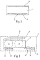
- Figure 2 shows the starting substrate 2 with a first Perforation strips 22 and a second perforation strip 23, another perforation strip 24 is assigned at right angles.
- the Perforation strips 22 and 23 are parallel and spaced apart along the long sides of the Output substrate 2 arranged.
- the starting substrate shown here is 2 shows a substrate in the “delivery state”. That is, the perforation strips 22, 23 and 24 are not open yet.
- FIG. 3 shows the mounting substrate 20 after it all necessary processing and assembly processes has passed through, here conductor tracks and components are not shown. Especially the mounting substrate 20 differs from the starting substrate 2 by opening the perforation strips 22, 23 and 24 and the spatial reorganization of the substrate strips 32, 33 and 34. The mounting substrate 20 is located accordingly in the "installed state”.
- Display instruments 25, 26 are exemplary here and 27 shown in dashed lines. There are also status indicators different vehicle functions shown, for example warning lights 28, 29 and a control lamp 30 for a direction indicator.
- the display instruments arranged here as examples 25, 26 and 27, warning lights 28, 29 and the control lamp 30 are part of a here only schematically shown instrument panel 31 of a motor vehicle, not shown here.
- Substrate strips 32, 33 and 34 released.
- the resulting substrate strips 32, 33 and 34 can be both in one plane relative to the main part of the mounting substrate 20 are shifted like this indicated by the substrate strips 32 and 33 will be folded down as well, as in the case of the Substrate strip 34 shown.
- Substrate strips 32, 33 and 34 can be saved in material firmly make an electrical connection between the display instruments 25, 26 and 27, the warning lights 28, 29 and the indicator light 30 manufacture.
- warning lights and indicator lights realized can be, including electronic Components and illuminants the respective display elements can be individually assigned.
- the perforated starting substrate enables a material-reduced and therefore inexpensive Manufacture of the display device and optimal use of the available substrate area.
- substrate strips which are formed after opening the perforation, both shifted in the plane and folded can be. Show folded substrate strips the advantage that with a one-sided assembly of the substrate in one operation or similar on the back of the substrate can be applied. This reduces the Processing costs.
Landscapes
- Engineering & Computer Science (AREA)
- Microelectronics & Electronic Packaging (AREA)
- Instrument Panels (AREA)
Abstract
Description
Die Erfindung betrifft eine Anzeigevorrichtung, insbesondere für ein Kraftfahrzeug, mit mindestens einem auf einem Substrat angeordneten Bauelement.The invention relates to a display device, especially for a motor vehicle, with at least a component arranged on a substrate.
Kombinationsinstrumente, insbesondere für Kraftfahrzeuge, zur Anzeige von beispielsweise Meßwerten sind bekannt. Diese weisen neben Gehäuse, Deckscheibe, Zeigern, Beleuchtungskörpern und elektrotechnischen Bauteilen häufig Substrate auf, die als Schaltungsträger und auch zur Herstellung elektrischer Verbindungen von Zeigerantrieben und Beleuchtungskörpern dienen.Combination instruments, in particular for motor vehicles, for displaying measured values, for example are known. In addition to the housing, cover plate, Hands, lighting fixtures and electrotechnical Components often on substrates that as Circuit carrier and also for the production of electrical Connections of pointer drives and lighting fixtures to serve.
Bei diesen Anzeigevorrichtungen hängt die geometrische Form des Substrats und dessen Größe von der Anordnung der Zeigerinstrumente und Beleuchtungskörper ab, ist mithin also designabhängig. Das heißt, die geometrischen Abmessungen des im Stand der Technik verwendeten Substrats müssen individuell an die verschieden ausgeführten Kombinationsinstrumente angepaßt werden. With these display devices, the geometrical depends Shape of the substrate and its size from the Arrangement of pointer instruments and lighting fixtures is therefore dependent on the design. The means the geometric dimensions of the in the stand The substrate used in the technology must be individual to the differently designed combination instruments be adjusted.
Nachteilig ist im Stand der Technik, daß durch die designabhängige Anordnung der Zeigerinstrumente und Beleuchtungskörper häufig nur eine sehr ungünstige Flächenausnutzung des Substrats erzielt werden kann.A disadvantage in the prior art is that design-dependent arrangement of the pointer instruments and Lighting fixtures often just a very inconvenient one Area utilization of the substrate can be achieved can.
Nachteilig ist im Stand der Technik weiterhin, daß für jedes Kombinationsinstrument und für jede Anordnungsvariante der Instrumente und Beleuchtungskörper eine individuelle Größe und Form des zur Instrumentenherstellung eingesetzten Substrats notwendig ist.Another disadvantage in the prior art is that for every combination instrument and for every arrangement variant of the instruments and lighting fixtures an individual size and shape of instrument manufacturing used substrate necessary is.
Die Erfindung betrifft eine Anzeigevorrichtung, insbesondere für ein Kraftfahrzeug, mit mindestens einem auf einem Montagesubstrat angeordneten Bauelement, wobei das Montagesubstrat durch Öffnen der Perforation eines mindestens eine Perforation aufweisenden Ausgangssubstats herstellbar ist.The invention relates to a display device, especially for a motor vehicle, with at least a component arranged on a mounting substrate, the mounting substrate by opening the Perforation of at least one perforation Starting substances can be produced.
Die Erfindung mit den Merkmalen des Anspruchs 1 hat
den Vorteil, daß sich mittels mindestens einer Perforation
des Ausgangssubstrats einfach und kostengünstig
Montagesubstrate unterschiedlicher Geometrie
verwirklichen lassen, wobei die geometrischen
Abmessungen des Ausgangssubstrats im wesentlichen
designunabhängig, also unabhängig vom Modell der
Anzeigevorrichtung und der Anordnung der Zeigerinstrumente
und der Beleuchtungskörper zueinander
sind. Das Ausgangssubstrat, beispielsweise eine Polyester-Folie,
kann designunabhängig und weitgehend
standardisiert hergestellt und ausgeführt werden,
wobei dennoch unterschiedliche Anordnungen der Zeigerinstrumente
und Beleuchtungskörper sowie verschiedenste
Ausführungsmodelle der Kombinationsinstrumente
verwirklicht werden können. Durch den
Einsatz eines durch Öffnen, beispielsweise Stanzen
oder Reißen, aus dem Ausgangssubstrat hergestellten
Montagesubstrats als Bauelementträger und elektrisches
Verbindungselement für elektrische und elektromechanische
Komponenten ergibt sich ein weiterer
Vorteil dadurch, daß sich eine sehr günstige Flächenausnützung
des Substrats erzielen läßt. Die
Herstellungskosten lassen sich so drastisch reduzieren.
Ein weiterer Vorteil der ein perforiertes
Ausgangssubstrat verwendenden erfindungsgemäßen Anzeigevorrichtung
besteht darin, daß nach dem Öffnen
der Perforationen ein so entstandener Substratstreifen
umgeklappt werden kann, so daß sich bei
einer einseitigen Bestückung des Substrats mit Bauelementen
verschiedener Art vorteilhafterweise auch
auf der Substratrückseite Bauelemente oder dergleichen
anbringen lassen.The invention has the features of
Im Zusammenhang mit der vorliegenden Erfindung wird unter dem Ausgangssubstrat das mindestens eine Perforation aufweisende Substrat im Anlieferungszustand, das heißt nach der Herstellung des Substrates und vor dem Einbau in die Anzeigevorrichtung, verstanden. Im Zusammenhang mit der vorliegenden Erfindung wird unter dem Montagesubstrat das Substrat verstanden, das durch Öffnen, beispielsweise Stanzen oder Reißen, der mindestens einen Perforation des Ausgangssubstrat aus diesem hervorgegangen ist. Nach dem Öffnen der Perforation können Teile des Substrates verschoben, verdreht, umgebogen oder abgeklappt werden, so daß sich der äußere Umriß des Ausgangssubstrats erheblich ändern kann. Die mittels des so hergestellten Montagesubstrats erreichbare Ausdehnung beziehungsweise dessen Verbindungspotential vergrößert sich demgemäß erheblich, so daß auch weiter auseinanderliegende Bauelemente der erfindungsgemäßen Anzeigevorrichtung verbunden werden können.In connection with the present invention at least one perforation under the starting substrate having substrate in the delivery state, that is after the production of the substrate and before installation in the display device, Understood. In connection with the present Invention is under the mounting substrate Understand substrate by opening, for example Punching or tearing the at least one Perforation of the starting substrate emerged from this is. After opening the perforation you can Parts of the substrate shifted, twisted, bent or be folded down so that the Significantly change the outer outline of the starting substrate can. By means of the mounting substrate thus produced achievable extent or its Connection potential increases accordingly considerably, so that they are further apart Components of the display device according to the invention can be connected.
In einer besonders bevorzugten Ausführungsform betrifft die Erfindung eine vorgenannte Anzeigevorrichtung, wobei das Ausgangssubstrat im wesentlichen eine rechteckige Grundform mit mindestens einer Perforation aufweist. In besonders bevorzugter Weise weist das Ausgangssubstrat zwei zueinander beabstandete und parallel zueinander verlaufende Perforationsstreifen auf, die beispielsweise parallel zu den Längsseiten des Ausgangssubstrats angeordnet sein können. In einer weiteren bevorzugten Ausführungsform ist ein weiterer Perforationsstreifen vorgesehen, der senkrecht von einer Längsseite des Ausgangssubstrats bis zu einem der parallel zu den Längsseiten des Ausgangssubstrats angeordneten anderen Perforationsstreifen verläuft. Durch Öffnen der längs und quer zu den Längsseiten des Ausgangssubstrats verlaufenden Perforationsstreifen lassen sich nach Umklappen oder Verschieben der nach der Öffnung der Perforation entstehenden Substratstreifen unterschiedlich geformte Montagesubstrate herstellen, die vorzüglich als Schaltungsträger und Verbindungselement für elektromechanische Komponenten geeignet sind.In a particularly preferred embodiment relates the invention a aforementioned display device, where the starting substrate is essentially a rectangular basic shape with at least one Has perforation. Particularly preferred The starting substrate points two to one another spaced and parallel to each other Perforation strips on, for example, parallel arranged to the long sides of the starting substrate could be. In another preferred The embodiment is another perforation strip provided vertically from one long side of the starting substrate up to one of the parallel to arranged along the long sides of the starting substrate other perforation strips. By opening the lengthways and crossways to the long sides of the starting substrate leave running perforation strips itself after folding or moving the after Opening of the perforation resulting substrate strips produce differently shaped mounting substrates, which are excellent as circuit carriers and Connection element for electromechanical components are suitable.
Vorteilhafte Ausgestaltungen der Erfindung ergeben sich aus den Unteransprüchen. Advantageous refinements of the invention result itself from the subclaims.
Die Erfindung wird im folgenden anhand eines Ausführungsbeispiels mit Bezug auf die Zeichnungen näher erläutert. Es zeigen:
Figur 1- eine Explosionszeichnung einer als Kombinationsinstrument ausgeführten Anzeigevorrichtung, wobei das Kombinationsinstrument in einer Seitenansicht mit einem Teilschnitt dargestellt ist,
Figur 2- eine Draufsicht eines Ausgangssubstrats, das heißt eines Substrats im Anlieferungszustand, mit den erfindungsgemäß vorgesehenen Perforationen und
- Figur 3
- eine Draufsicht auf ein Montagesubstrat, das heißt eines sich im Einbauzustand befindenden Substrats, welches verschobene und geklappte Substratstreifen aufweist.
- Figure 1
- 2 shows an exploded drawing of a display device designed as a combination instrument, the combination instrument being shown in a side view with a partial section,
- Figure 2
- a plan view of a starting substrate, that is to say a substrate in the delivery state, with the perforations and
- Figure 3
- a plan view of a mounting substrate, that is, a substrate in the installed state, which has shifted and folded substrate strips.
In Figur 1 ist ein Kombinationsinstrument 1 in einer
Explosionszeichnung dargestellt. Das Kombinationsinstrument
1 umfaßt ein Montagesubstrat 20,
beispielsweise eine Polyester-Folie, einen Reflektor
3, eine Leuchtscheibe 4, ein Zifferblatt 5,
einen Zeiger 6, einen Frontrahmen 7 sowie eine
Deckscheibe 8. Auf dem Montagesubstrat 20 ist ein
Leuchtmittel 9, ein Zeigerantrieb 10 und ein elektronisches
Bauteil 11 angebracht. Der Reflektor 3
weist ein Mittelloch 12 sowie einen Durchbruch 13,
ein Befestigungselement 14 sowie eine Fixierungseinrichtung
15 auf. In Figure 1 is a
Die Leuchtscheibe 4 weist ebenfalls ein Mittelloch
18 sowie eine Aufnahmeeinrichtung 19, die zur Aufnahme
der Fixierungseinrichtung 15 dient, auf.The light disk 4 also has a center hole
18 and a receiving device 19 for recording
the
Dem Zifferblatt 5 ist ein Mittelloch 16 sowie eine
Aufnahme 17 für die Fixierungseinrichtung 15 zugeordnet.The dial 5 is a center hole 16 and one
Recording 17 assigned to the
Dargestellt ist ferner ein hinter dem Frontrahmen 7
und der Deckscheibe 8 angeordneter und mit dem Zeigerantrieb
10 verbundener Zeiger 6. Daraus ergibt
dich für das zusammengesetzte Kombinationsinstrument
1, das hier nicht dargestellt ist, ein Aufbau,
bei dem die Leuchtscheibe 4 in den Reflektor 3 eingesetzt
wird, so daß die Fixierungseinrichtung 15
in die Aufnahmeeinrichtung 19 eingreift und die
Leuchtscheibe 4 vom Befestigungselement 14 gehalten
wird, wobei die Mittelachsen der Leuchtscheibe 4
und des Reflektors 3 miteinander fluchten. Nachdem
die Leuchtscheibe 4 in den Reflektor 3 eingesetzt
wurde, wird das Zifferblatt 5 in gleicher Weise wie
die Leuchtscheibe 4 dem Reflektor 3 zugeordnet. Das
erfolgt dadurch, daß das Zifferblatt 5 auf den Reflektor
3 aufgesteckt wird, wobei die Fixierungseinrichtung
15 in die Aufnahmeeinrichtung 17 eingreift
und das Zifferblatt 5 durch das Befestigungselement
14 gehalten wird, wobei die Mittelachsen
der so zusammengesetzten Teile miteinander
fluchten. Anschließend wird das Montagesubstrat 20
von der in Figur 1 dargestellten rechten Seite auf
den Reflektor 3 aufgesteckt. Das Montagesubstrat 20
kann hierbei durch hier nicht dargestellte Befestigungsmittel
auf dem Reflektor 3 befestigt werden.
Ist das Montagesubstrat 20 dem Reflektor 3 zugeordnet,
so erstreckt sich das Leuchtmittel 9 in den
Durchbruch 13 und der Zeigerantrieb 10 ragt mit einer
Antriebsachse 35 durch die Mittellöcher 12, 18
und 16. Nachdem der Zusammenbau des Kombinationsinstruments
1 soweit bewerkstelligt ist, kann der
Zeiger 6 mit einem Fortsatz 21, der eine hier nicht
sichtbare Aufnahme beinhaltet, auf die Antriebsachse
35 des Zeigerantriebs 10 aufgesteckt werden.
Nachdem der Zeiger 6 auf der Antriebsachse 35 befestigt
wurde, kann die so entstandene Einheit, bestehend
aus Montagesubstrat 20, Reflektor 3,
Leuchtscheibe 4 und Zifferblatt 5 mit dem Frontrahmen
7 verbunden werden. Auf dem Frontrahmen 7 ist
zum Schutz des Anzeigeinstruments, das heißt, zum
Schutz der beweglichen Elemente, beispielsweise des
Zeigers 6, eine Deckscheibe 8 aufgebracht.Also shown is behind the front frame 7
and the cover plate 8 arranged and with the
Figur 2 zeigt das Ausgangssubstrat 2 mit einem ersten
Perforationsstreifen 22 und einem zweiten Perforationsstreifen
23, dem ein weiterer Perforationsstreifen
24 rechtwinklig zugeordnet ist. Die
Perforationsstreifen 22 und 23 sind parallel und
beabstandet zueinander entlang der Längsseiten des
Ausgangssubstrats 2 angeordnet.Figure 2 shows the
Wie bereits erwähnt, ist das hier dargestellte Ausgangssubstrat
2 ein Substrat im "Anlieferungszustand".
Das heißt, die Perforationsstreifen 22, 23
und 24 sind noch nicht geöffnet.As already mentioned, the starting substrate shown here is
2 shows a substrate in the “delivery state”.
That is, the
Figur 3 zeigt das Montagesubstrat 20, nachdem es
sämtliche notwendigen Bearbeitungs- und Bestückungsvorgänge
durchlaufen hat, wobei hier Leiterbahnen
und Bauelemente nicht dargestellt sind. Insbesondere
unterscheidet sich das Montagesubstrat 20
vom Ausgangssubstrat 2 durch das erfolgte Öffnen
der Perforationsstreifen 22, 23 und 24 und die
räumliche Neuordnung der entstandenen Substratstreifen
32, 33 und 34. Das Montagesubstrat 20 befindet
sich demgemäß im "Einbauzustand".Figure 3 shows the
Beispielhaft sind hier Anzeigeinstrumente 25, 26
und 27 gestrichelt dargestellt. Weiterhin sind Zustandsanzeiger
verschiedener Fahrzeugfunktionen gezeigt,
beispielsweise Warnleuchten 28, 29 sowie
eine Kontrollampe 30 für einen Fahrtrichtungsanzeiger.
Die hier beispielhaft angeordneten Anzeigeinstrumente
25, 26 und 27, die Warnleuchten 28, 29
und die Kontrolleuchte 30 sind Bestandteil einer
hier nur schematisch dargestellten Instrumententafel
31 eines hier nicht dargestellten Kraftfahrzeugs.
Wie in Figur 3 erkennbar, werden nach dem Öffnen
der Perforationsstreifen 22, 23 und 24 entsprechende
Substratstreifen 32, 33 und 34 freigegeben.
Die so entstandenen Substratstreifen 32, 33 und 34
können sowohl in einer Ebene relativ zum Hauptteil
des Montagesubstrat 20 verschoben werden, wie dies
durch die Substratstreifen 32 und 33 angezeigt
wird, als auch umgeklappt werden, wie im Fall des
Substratstreifens 34 dargestellt.As can be seen in Figure 3, after opening
the perforation strips 22, 23 and 24 respectively
Substrate strips 32, 33 and 34 released.
The resulting substrate strips 32, 33 and 34
can be both in one plane relative to the main part
of the mounting
Mit den so hergestellten und räumlich angeordneten
Substratstreifen 32, 33 und 34 läßt sich in materialsparender
Weise leicht eine elektrische Verbindung
zwischen den Anzeigeinstrumenten 25, 26 und
27, den Warnleuchten 28, 29 und der Kontrolleuchte
30 herstellen.With the so produced and spatially arranged
Substrate strips 32, 33 and 34 can be saved in material
Easily make an electrical connection
between the
Es ist leicht ableitbar, daß mit derselben geometrischen
Form des Ausgangsubstrats 2, jedoch mit
anders verlaufenden oder weiteren Perforationsstreifen
eine andere Anordnung der Anzeigeinstrumente,
der Warnleuchten und Kontrolleuchten verwirklicht
werden kann, wobei auch elektronische
Bauteile und Leuchtmittel den jeweiligen Anzeigeelementen
individuell zugeordnet werden können.It is easy to deduce that with the same geometric
Shape of the starting
Nach alledem wird klar, daß der Einsatz eines perforierten Ausgangssubstrats als Bauelementträger und elektrisches Verbindungselement für elektromechanische und elektrotechnische Komponenten einer Anzeigevorrichtung in vorteilhafter Weise möglich ist. Weiterhin ermöglicht das perforierte Ausgangssubstrat eine materialreduzierte und damit kostengünstige Herstellung der Anzeigevorrichtung und eine optimale Ausnutzung der vorhandenen Substratfläche.After all, it becomes clear that the use of a perforated Starting substrate as component carrier and electrical connector for electromechanical and electrotechnical components one Display device possible in an advantageous manner is. Furthermore, the perforated starting substrate enables a material-reduced and therefore inexpensive Manufacture of the display device and optimal use of the available substrate area.
Weiterhin ist ersichtlich, daß Substratstreifen, die nach Öffnen der Perforierung gebildet werden, sowohl in der Ebene verschoben als auch geklappt werden können. Geklappte Substratstreifen weisen den Vorteil auf, daß bei einer einseitigen Bestückung des Substrats in einem Arbeitsgang Beleuchtungsmittel oder ähnliches auf der Substratrückseite aufgebracht werden können. Dies reduziert die Bearbeitungskosten.It can also be seen that substrate strips, which are formed after opening the perforation, both shifted in the plane and folded can be. Show folded substrate strips the advantage that with a one-sided assembly of the substrate in one operation or similar on the back of the substrate can be applied. This reduces the Processing costs.
Es ist jedoch auch denkbar, daß, nachdem der Substratstreifen umgeklappt und seine Rückseite bestückt wurde, der Substratstreifen wieder zurückgeklappt wird, um anschließend seine Vorderseite zu bestücken.However, it is also conceivable that after the substrate strip folded down and its back loaded the substrate strip was folded back will then turn to its front equip.
Claims (8)
Applications Claiming Priority (2)
| Application Number | Priority Date | Filing Date | Title |
|---|---|---|---|
| DE19651863A DE19651863A1 (en) | 1996-12-13 | 1996-12-13 | Display device |
| DE19651863 | 1996-12-13 |
Publications (2)
| Publication Number | Publication Date |
|---|---|
| EP0848583A1 true EP0848583A1 (en) | 1998-06-17 |
| EP0848583B1 EP0848583B1 (en) | 2003-03-26 |
Family
ID=7814583
Family Applications (1)
| Application Number | Title | Priority Date | Filing Date |
|---|---|---|---|
| EP97117125A Expired - Lifetime EP0848583B1 (en) | 1996-12-13 | 1997-10-02 | Display device |
Country Status (2)
| Country | Link |
|---|---|
| EP (1) | EP0848583B1 (en) |
| DE (2) | DE19651863A1 (en) |
Cited By (1)
| Publication number | Priority date | Publication date | Assignee | Title |
|---|---|---|---|---|
| EP1168897A2 (en) * | 2000-06-30 | 2002-01-02 | Coroplast Fritz Müller GmbH & Co. KG | Foil printed circuit board and process for manufacturing and mounting the same |
Families Citing this family (1)
| Publication number | Priority date | Publication date | Assignee | Title |
|---|---|---|---|---|
| DE10029729A1 (en) * | 2000-06-16 | 2002-02-21 | Mannesmann Vdo Ag | Instrument cluster for displaying measured values and / or other information, in particular for use in a motor vehicle |
Citations (4)
| Publication number | Priority date | Publication date | Assignee | Title |
|---|---|---|---|---|
| EP0126856A2 (en) * | 1983-05-21 | 1984-12-05 | GRUNDIG E.M.V. Elektro-Mechanische Versuchsanstalt Max Grundig holländ. Stiftung & Co. KG. | Method of making a circuit board having rigid and flexible areas |
| US4569885A (en) * | 1981-08-20 | 1986-02-11 | Nitto Electric Industrial Company, Limited | Polyester film for forming printed circuit |
| DE3500899A1 (en) * | 1985-01-12 | 1986-07-17 | Benny S - car + boat Technik + Design Team GmbH, 5650 Solingen | Indicating instrument with quasi-continuous display |
| DE3904656A1 (en) * | 1989-02-16 | 1990-08-23 | Vdo Schindling | POINTER INSTRUMENT |
-
1996
- 1996-12-13 DE DE19651863A patent/DE19651863A1/en not_active Withdrawn
-
1997
- 1997-10-02 EP EP97117125A patent/EP0848583B1/en not_active Expired - Lifetime
- 1997-10-02 DE DE59709619T patent/DE59709619D1/en not_active Expired - Lifetime
Patent Citations (4)
| Publication number | Priority date | Publication date | Assignee | Title |
|---|---|---|---|---|
| US4569885A (en) * | 1981-08-20 | 1986-02-11 | Nitto Electric Industrial Company, Limited | Polyester film for forming printed circuit |
| EP0126856A2 (en) * | 1983-05-21 | 1984-12-05 | GRUNDIG E.M.V. Elektro-Mechanische Versuchsanstalt Max Grundig holländ. Stiftung & Co. KG. | Method of making a circuit board having rigid and flexible areas |
| DE3500899A1 (en) * | 1985-01-12 | 1986-07-17 | Benny S - car + boat Technik + Design Team GmbH, 5650 Solingen | Indicating instrument with quasi-continuous display |
| DE3904656A1 (en) * | 1989-02-16 | 1990-08-23 | Vdo Schindling | POINTER INSTRUMENT |
Cited By (2)
| Publication number | Priority date | Publication date | Assignee | Title |
|---|---|---|---|---|
| EP1168897A2 (en) * | 2000-06-30 | 2002-01-02 | Coroplast Fritz Müller GmbH & Co. KG | Foil printed circuit board and process for manufacturing and mounting the same |
| EP1168897A3 (en) * | 2000-06-30 | 2004-01-02 | Coroplast Fritz Müller GmbH & Co. KG | Foil printed circuit board and process for manufacturing and mounting the same |
Also Published As
| Publication number | Publication date |
|---|---|
| DE19651863A1 (en) | 1998-06-18 |
| EP0848583B1 (en) | 2003-03-26 |
| DE59709619D1 (en) | 2003-04-30 |
Similar Documents
| Publication | Publication Date | Title |
|---|---|---|
| EP1019260B1 (en) | Measuring system, especially for display devices in the automobile technology | |
| DE2913138A1 (en) | DISPLAY DEVICE | |
| DE3902956A1 (en) | ARRANGEMENT FOR AN INSTRUMENT PANEL OR A PART OF AN INSTRUMENT PANEL, IN PARTICULAR FOR MOTOR VEHICLES | |
| DE19757545A1 (en) | Display device for automobile dashboard | |
| DE19652139C1 (en) | Display unit | |
| EP0848583B1 (en) | Display device | |
| DE2611434A1 (en) | LIGHTING DEVICE FOR DISPLAY INSTRUMENTS | |
| DE69308401T2 (en) | Control panel with touch buttons for the control of an air conditioning system of a vehicle interior | |
| DE3113773C2 (en) | ||
| DE4440148A1 (en) | Tubular housing | |
| DE2607398B2 (en) | Battery operated electric clock with alarm device | |
| DE2546842A1 (en) | INSTRUMENT ARRANGEMENT | |
| DE2128859A1 (en) | Timer module | |
| DE3735004A1 (en) | Indicator device | |
| EP2567853B1 (en) | Holder element for fixing an electric motor to an electronic circuit board, display device of a motor vehicle comprising an electrical display instrument with an electric motor fixed to an electronic circuit board by means of such a holder element and method for fixing an electric engine to an electronic circuit board by means of such a holder element | |
| DE19704600A1 (en) | Motor vehicle dashboard with printed circuit tracks formed on housing | |
| DE29618395U1 (en) | Display instrument with an illuminated display panel | |
| EP0755822A2 (en) | Display device for functions and operating states of a motor vehicle | |
| EP1136870B1 (en) | Displaying device | |
| DE3207616C3 (en) | Electrical clockwork, in particular quartz clockwork | |
| DE2756358A1 (en) | ELECTRONIC WATCH WITH DIGITAL DISPLAY | |
| AT408283B (en) | DOOR INTERCOM WITH ONE DEVICE FRONT PANEL | |
| DE2903830A1 (en) | Electrical connector for motor cars - using thrust module on printed circuit boards on plastic instrument casing | |
| DE102014003864A1 (en) | Electronic device and operating arrangement with an electronic device | |
| DE102019213669A1 (en) | Steering column |
Legal Events
| Date | Code | Title | Description |
|---|---|---|---|
| PUAI | Public reference made under article 153(3) epc to a published international application that has entered the european phase |
Free format text: ORIGINAL CODE: 0009012 |
|
| AK | Designated contracting states |
Kind code of ref document: A1 Designated state(s): DE FR GB IT |
|
| AX | Request for extension of the european patent |
Free format text: AL;LT;LV;RO;SI |
|
| 17P | Request for examination filed |
Effective date: 19981217 |
|
| AKX | Designation fees paid |
Free format text: DE FR GB IT |
|
| RBV | Designated contracting states (corrected) |
Designated state(s): DE FR GB IT |
|
| 17Q | First examination report despatched |
Effective date: 19990315 |
|
| GRAH | Despatch of communication of intention to grant a patent |
Free format text: ORIGINAL CODE: EPIDOS IGRA |
|
| GRAH | Despatch of communication of intention to grant a patent |
Free format text: ORIGINAL CODE: EPIDOS IGRA |
|
| GRAA | (expected) grant |
Free format text: ORIGINAL CODE: 0009210 |
|
| AK | Designated contracting states |
Designated state(s): DE FR GB IT |
|
| REG | Reference to a national code |
Ref country code: GB Ref legal event code: FG4D Free format text: NOT ENGLISH |
|
| REF | Corresponds to: |
Ref document number: 59709619 Country of ref document: DE Date of ref document: 20030430 Kind code of ref document: P |
|
| GBT | Gb: translation of ep patent filed (gb section 77(6)(a)/1977) | ||
| ET | Fr: translation filed | ||
| PLBE | No opposition filed within time limit |
Free format text: ORIGINAL CODE: 0009261 |
|
| STAA | Information on the status of an ep patent application or granted ep patent |
Free format text: STATUS: NO OPPOSITION FILED WITHIN TIME LIMIT |
|
| 26N | No opposition filed |
Effective date: 20031230 |
|
| PGFP | Annual fee paid to national office [announced via postgrant information from national office to epo] |
Ref country code: IT Payment date: 20091023 Year of fee payment: 13 Ref country code: GB Payment date: 20091023 Year of fee payment: 13 Ref country code: FR Payment date: 20091110 Year of fee payment: 13 |
|
| PGFP | Annual fee paid to national office [announced via postgrant information from national office to epo] |
Ref country code: DE Payment date: 20091215 Year of fee payment: 13 |
|
| GBPC | Gb: european patent ceased through non-payment of renewal fee |
Effective date: 20101002 |
|
| PG25 | Lapsed in a contracting state [announced via postgrant information from national office to epo] |
Ref country code: FR Free format text: LAPSE BECAUSE OF NON-PAYMENT OF DUE FEES Effective date: 20101102 |
|
| REG | Reference to a national code |
Ref country code: FR Ref legal event code: ST Effective date: 20110630 |
|
| REG | Reference to a national code |
Ref country code: DE Ref legal event code: R119 Ref document number: 59709619 Country of ref document: DE Effective date: 20110502 |
|
| PG25 | Lapsed in a contracting state [announced via postgrant information from national office to epo] |
Ref country code: GB Free format text: LAPSE BECAUSE OF NON-PAYMENT OF DUE FEES Effective date: 20101002 |
|
| PG25 | Lapsed in a contracting state [announced via postgrant information from national office to epo] |
Ref country code: IT Free format text: LAPSE BECAUSE OF NON-PAYMENT OF DUE FEES Effective date: 20101002 |
|
| PG25 | Lapsed in a contracting state [announced via postgrant information from national office to epo] |
Ref country code: DE Free format text: LAPSE BECAUSE OF NON-PAYMENT OF DUE FEES Effective date: 20110502 |