EP0847945B1 - Article transfer station - Google Patents
Article transfer station Download PDFInfo
- Publication number
- EP0847945B1 EP0847945B1 EP97309777A EP97309777A EP0847945B1 EP 0847945 B1 EP0847945 B1 EP 0847945B1 EP 97309777 A EP97309777 A EP 97309777A EP 97309777 A EP97309777 A EP 97309777A EP 0847945 B1 EP0847945 B1 EP 0847945B1
- Authority
- EP
- European Patent Office
- Prior art keywords
- station
- receivers
- articles
- support member
- conveyor
- Prior art date
- Legal status (The legal status is an assumption and is not a legal conclusion. Google has not performed a legal analysis and makes no representation as to the accuracy of the status listed.)
- Expired - Lifetime
Links
- 238000000034 method Methods 0.000 claims description 8
- 238000007789 sealing Methods 0.000 description 18
- 239000000969 carrier Substances 0.000 description 6
- 230000007246 mechanism Effects 0.000 description 6
- 230000005540 biological transmission Effects 0.000 description 4
- 238000004806 packaging method and process Methods 0.000 description 3
- 241000239290 Araneae Species 0.000 description 2
- 210000003746 feather Anatomy 0.000 description 2
- 239000000945 filler Substances 0.000 description 1
- 239000007788 liquid Substances 0.000 description 1
- 230000014759 maintenance of location Effects 0.000 description 1
- 230000000717 retained effect Effects 0.000 description 1
- 238000005096 rolling process Methods 0.000 description 1
- 239000010902 straw Substances 0.000 description 1
- 229920001169 thermoplastic Polymers 0.000 description 1
- 239000004416 thermosoftening plastic Substances 0.000 description 1
Images
Classifications
-
- B—PERFORMING OPERATIONS; TRANSPORTING
- B65—CONVEYING; PACKING; STORING; HANDLING THIN OR FILAMENTARY MATERIAL
- B65B—MACHINES, APPARATUS OR DEVICES FOR, OR METHODS OF, PACKAGING ARTICLES OR MATERIALS; UNPACKING
- B65B43/00—Forming, feeding, opening or setting-up containers or receptacles in association with packaging
- B65B43/42—Feeding or positioning bags, boxes, or cartons in the distended, opened, or set-up state; Feeding preformed rigid containers, e.g. tins, capsules, glass tubes, glasses, to the packaging position; Locating containers or receptacles at the filling position; Supporting containers or receptacles during the filling operation
- B65B43/50—Feeding or positioning bags, boxes, or cartons in the distended, opened, or set-up state; Feeding preformed rigid containers, e.g. tins, capsules, glass tubes, glasses, to the packaging position; Locating containers or receptacles at the filling position; Supporting containers or receptacles during the filling operation using rotary tables or turrets
-
- B—PERFORMING OPERATIONS; TRANSPORTING
- B65—CONVEYING; PACKING; STORING; HANDLING THIN OR FILAMENTARY MATERIAL
- B65G—TRANSPORT OR STORAGE DEVICES, e.g. CONVEYORS FOR LOADING OR TIPPING, SHOP CONVEYOR SYSTEMS OR PNEUMATIC TUBE CONVEYORS
- B65G47/00—Article or material-handling devices associated with conveyors; Methods employing such devices
- B65G47/74—Feeding, transfer, or discharging devices of particular kinds or types
- B65G47/84—Star-shaped wheels or devices having endless travelling belts or chains, the wheels or devices being equipped with article-engaging elements
- B65G47/846—Star-shaped wheels or wheels equipped with article-engaging elements
Definitions
- This invention relates generally to transfer stations and, more particularly, to a carton transfer station wherein there is no change in orientation of a carton being transferred.
- US-A-1,431,930; US-A-3,868,009; and US-A- 5,188,212 each disclose rotary apparatus for transferring articles without changing the orientation of the same.
- the apparatus includes a swivel arm with a vertical axis, and a rotary plate rotatably mounted on the swivel arm axis, extending at least partially to the first and second conveyors.
- a drive is provided for rotating the rotary plate.
- Carriers are rotatably mounted beneath the rotary plate, at regular intervals along the periphery of the rotary plate.
- the carriers have a carrier axis for counter rotation and grippers for consecutively gripping sanitary napkins conveyed by the first conveyor.
- the napkins are transported to a second conveyor, and placed on the second conveyor without altering the orientation of the napkin with respect to the first conveyor.
- the operating radius between the centre of the rotary plate and the carriers is variable.
- a fixed, central ratchet wheel is connected by one or more toothed belts to outer ratchet wheels fixed to the carriers. As the rotary plate spins anti-clockwise, the central and outer ratchet wheels and the belts drive the carriers clockwise, so that the napkins maintain the same orientation with respect to the conveyors.
- US-A-5,029,695 is representative of a starwheel for transferring articles in an oriented position around its periphery from one conveyor mechanism to another.
- GB-A-2100696 discloses a machine for forming, filling and sealing cartons and comprised of eight work stations, namely a straw and sealing tape applicator station, a carton blank wrapping and folding station, a seam and one end bonding station, a carton rotator and conveyor transport station, an other end closure preform station, a filler station, an other end closure sealing station, and a carton ejector station.
- work stations namely a straw and sealing tape applicator station, a carton blank wrapping and folding station, a seam and one end bonding station, a carton rotator and conveyor transport station, an other end closure preform station, a filler station, an other end closure sealing station, and a carton ejector station.
- every carton blank is transferred onto a rotary crossbar mandrel having a horizontal axis, and through a series of operations, a side seam of the carton is sealed, and one end closure of the carton is formed and sealed.
- every carton is removed from the crossbar mandrel, turned through a right-angle about its own longitudinal axis, which is horizontal, and inserted upon a conveyor on which the carton remains until ejected from the machine.
- US-A-4337059 discloses a packaging machine for forming, filling and sealing cartons, in which machine cartons are indexed in pairs through various work stations to accomplish forming, filling and sealing of the cartons.
- the forming of the bottom closures of the cartons is performed upon a rotary turret having a vertical axis.
- the turret is stepped about its axis to bring the cartons into the stations in turn and is of a type which includes two mandrels at each station and which indexes two mandrels from one station to the next station.
- the bottom-closed, open-topped cartons are advanced stepwise linearly by a chain conveyor through various stations in which the cartons are filled and top closures thereof are formed.
- a difficulty with this machine is that a carton having its top and bottom closures orientated parallelly to each other and a carton having its top and bottom closures orientated perpendicularly to each other require differing machine layouts, especially in respect of the top and bottom closure forming stations.
- a one-litre gable-topped carton was introduced shortly before the civilization War, with a half-gallon (or two-litre) gable-topped carton appearing at about the end of that War.
- Each carton sleeve has its bottom closed by folding-in and sealing of bottom closure panels, is then filled and has its top closed by folding-in and sealing of top closure panels.
- Each closure includes two major panels at respective opposite sides of the sleeve. In the half-gallon carton sleeve, the two major panels of the top closure are initially substantially co-planar with the two major panels of the bottom closure.
- the two major panels of the top closure initially lie in planes substantially perpendicular to those in which lie the two major panels of the bottom closure.
- those cartons in which the gable top major panels are orientated the same as those of the bottom closure are called “standard fifth panel” cartons and those cartons in which the gable top major panels are orientated 90° from those of the bottom closure are called “reverse fifth panel cartons”.
- the machine includes a spider rotatable about a horizontal axis and having its arms in the form of respective mandrels upon which the carton sleeves are mounted and then bottom-closed.
- the bottom-closed cartons are transferred in turn from the mandrels to pockets of a chain conveyor for subsequent filling and then top-folding and sealing.
- the top-sealing is performed by sealing jaws.
- a relatively complicated transfer mechanism including a suction cup which is rotatable about its own axis and is spatially displaceable.
- the mandrels in turn present their respective bottom-closed carton sleeves to the suction cup which is advanced to seize the bottom closure of the carton sleeve and is then withdrawn to remove the carton sleeve from the mandrel and to transfer it to a pocket of the chain conveyor.
- the suction cup is rotated through 90° about its own axis while carrying out the transfer. Not only is this transfer mechanism relatively complicated, but it requires significant space.
- a machine similar to that just described is disclosed in US-E-26656.
- EP-B-0355063 discloses a packaging system in which carton sleeves are sealingly closed at their bottoms while received upon respective mandrels, the open-topped cartons so formed are removed from the mandrels and filled, and the filled cartons are sealingly closed at their tops. Between the bottoms being sealingly closed and the cartons being filled, half-gallon cartons are turned through a right-angle about their own axes to bring their top closure sealing sub-panels into a correct orientation for top-sealing. For enabling such turning, the mandrels are mounted on a turntable so as to be turnable about their own axes by a cam displaceable between operative and inoperative positions. The turntable is of a rotary turret which indexes the carton sleeves through various stations mostly concerned with bottom-closing.
- DE-A-19513411 discloses a device for positioning a radial conveyor in a bottle handling system and a method of fastening and changing the radial conveyor, so that it transmits power and is centered and accurately positioned on the flange of a drive hub. Separate transmission, centering and fastening elements are provided specifically for transmitting power, centering and fastening the radial conveyor through or onto the flange.
- Power transmission, centering and fastening are achieved by giving the flange a through radial groove, in one side of which is fixed a feather key as transmission element, and, as a structural component mounted on this flange, the radial conveyor is centred and clamped between a centering ring matching the flange diameter and a locking ring, the locking ring also having a through radial groove in one side of which is located a feather key as a transmission element.
- an article transfer station for transferring articles from a first conveyor to a second conveyor, comprising means whereby the station can be selected to be either a station at which articles are carried through a predetermined angle about a substantially vertical axis while changing their orientations by said angle, or a station at which articles are carried through said predetermined angle about said axis without changing their orientations, said means comprising a first device turnable about said axis and including first receivers for receiving respective articles, and a mount mounting said device and turnable about said axis, characterised by a connector readily releasably connecting said device to said mount and whereby said device can be disconnected from said mount for replacement by a second device including second receivers for receiving respective articles.
- a method comprising selecting an article transfer station, for transferring articles from a first conveyor to a second conveyor, to be either a station at which articles are carried through a predetermined angle about a substantially vertical axis while changing their orientations by said angle, or a station at which articles are carried through said predetermined angle about said axis without changing their orientations, characterised in that said selecting comprises selecting to connect to a rotary mount at the station either a first device including first article-receivers rotatable relative to a first support member included in said first device, or a second device including second article-receivers fixed to a second support member included in said second device.
- a rotary transfer device has four receivers, wherein two articles, such as four-sided cartons, may be received simultaneously in two oppositely disposed receivers, rotated 90°, and deposited onto one underlying conveyor in series, while receiving two more articles in the other two oppositely disposed receivers.
- the station includes a rotary transfer device including a rotatable support member for rotation by a central drive member, and four gears rotatably mounted on the support member while movable with the support member and in mesh with four pinions themselves in mesh with a central gear and a receiver formed in each of the four gears.
- pulleys are used in lieu of the central gear and the four gears, and belts are used in lieu of the four pinions and mounted around the pulleys.
- the rotary transfer device is replaceable by a second rotary transfer device in which other receivers are fixed to another rotatable support member.
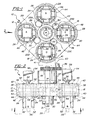
- Figures 1 and 2 illustrate a transfer station including a rotary transfer device 10 including a support member 12 rotatably mounted around a central fixed gear 14.
- a rotary transfer device 10 including a support member 12 rotatably mounted around a central fixed gear 14.
- Four equally spaced outer gears 16, 18, 20 and 22 are mounted on the support member 12, outwardly of the central fixed gear 14.
- An idler gear 23A is in mesh with the central fixed gear 14 and the adjacent outer gear 22.
- an idler gear 23B is in mesh with the gears 14 and 16; an idler gear 23C with the gears 14 and 18; and an idler gear 23D with the gears 14 and 20.
- each gear 16, 18, 20 and 22 forming respective pockets or receivers A, B, C and D suitable for receiving articles, such as open-topped cartons to be filled with liquids downstream of the transfer station.
- the fixed central gear 14 is secured by bolts 32 to a member 34.
- the support member 12 is rotatably fixed to a central shaft 35 driven by an external source, represented as 36.
- a member 37 between the support 12 and drive source 36 serves as a guide for the shaft 35 extending therethrough.
- the member 12 is fixed to the shaft 35 by means of a C-clip 39 welded to the member 12 and fixed longitudinally of the shaft 35 by clamping screws 31 and fixed peripherally of the shaft 35 by a key 33.
- Each outer gear 16, 18, 20 and 22 is formed as a midportion of upper and lower cylindrical extensions 38 and 40, respectively.
- the cylindrical extensions are rotatably mounted within respective upper and lower bearings 42 and 44 mounted in annular recesses 46 formed in the support member 12.
- Each lower cylindrical extension 40 has seated thereon a flange 48 formed around each set of four corner abutment members 24, 26, 28 and 30 and attached to the extension 40 by means of screws 41.
- a chamfered edge 52 is formed at each end of each of the corner abutment members 24, 26, 28 and 30, serving to pilot a four-sided carton, represented as 54, into a respective pocket A, B, C or D, wherein it is retained in a friction fit.
- each of the pockets A and C receives a bottom-closed, thermoplastic-coated carton 54 via stripper mechanisms represented as 56 in Figure 2, from respective mandrels, represented as 58, of a bottom forming turret, not shown here, but such as shown and described in U.S. Patent No. 4,590,740.
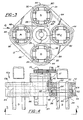
- the two cartons 54 After being indexed 90° (during which the rolling of the gears 16 to 22 causes the two cartons 54 in the pockets A and C to maintain their original orientation), the two cartons 54, now in the respective locations B and D in Figure 1, are pulled downwardly by any suitable additional stripper mechanisms, represented as 59 in Figure 2, similar to the stripper mechanism 56, out of their respective pockets onto a single line conveyor, represented as 60 in Figure 1, to thereafter be indexed through top filling, forming, and sealing stations, such as shown and described in the above referenced Patent No. 4,590,740. Concurrently, the pockets B and D, now in the respective positions shown as A and C, receive two additional cartons 54 from the next two mandrels 58.
- any suitable additional stripper mechanisms represented as 59 in Figure 2
- the pockets B and D now in the respective positions shown as A and C, receive two additional cartons 54 from the next two mandrels 58.
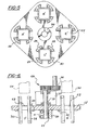
- a central double width pulley 62 is used in lieu of the central gear 14
- pulleys 80, 82, 84 and 86 are used in lieu of the four outer gears 16, 18, 20 and 22, and two belts 64 and 66 are used in lieu of the four idler gears 23A to 23D.
- Each belt is mounted around the central pulley 62 and around two adjacent pulleys 80/82, and 84/86, which are rotatably mounted on the support 12.
- the four corner abutment members 24, 26, 28 and 30 are secured within each of the pulleys 80, 82, 84 and 86.
- the rotary transfer device 10b of Figures 5 and 6 differs from the devices 10 and 10a of Figures 1 to 4 in that the gears of the Figures 1 and 2 embodiment, and the belts of the Figures 3 and 4 embodiment, are omitted, and the vertically oriented corner abutment members 24, 26, 28 and 30 are secured, in rectangular openings 63 through a support member 12', in any suitable manner, for example (as shown) by the screws 41 through their flanges 48, directly to the support member 12', to provide respective receivers A', B', C' and D'.
- the device 10b is substituted for the device 10 or 10a, by loosening the screws 31 of the device 10 or 10a, sliding the device 10 or 10a downwardly off the shaft 35, sliding the device 10b upwardly onto the shaft 35 and then tightening the clamping screws 31 of the device 10b to clamp it to the shaft.
- both the standard fifth panel cartons and the reverse fifth panel cartons (wherein the gable top closure panels are oriented 90° from those of the standard fifth panel carton, but must be conveyed through the downstream top filling, forming, and sealing in the same orientation) can be processed through the bottom-forming turret without any changes therein.
- a packaging machine manufacturer can simply select either the device 10 or 10a or the device 10b for fitting to a machine to be supplied to a package producer, depending upon whether the machine is to run standard fifth panel cartons or reverse fifth panel cartons, or can supply together with the machine both the device 10 or 10a and the device 10b, so that the producer can readily change the machine over from one style of carton to the other.
- a possible alternative to having two different kinds of device 10 (or 10a) and 10b is that the device 10 or 10a could have its idler gears 23A to 23D, or belts 64 and 66, disengageable and its gears 16 to 22, or pulleys 80 to 86, fixable to the rotary support member 12.
- the machine manufacturer can then send out the machine either with its idler gears or belts disengaged and its outer gears or pulleys fixed to the rotary support member, or with its idler gears or belts engaged and its outer gears or pulleys rotatable relative to the support member. Otherwise, the package producer can change-over the device from one condition to the other.
- each outer gear or ring could be formed in any desired shape other than the four corner abutment members, to accommodate a variety of carton shapes.
Landscapes
- Engineering & Computer Science (AREA)
- Mechanical Engineering (AREA)
- Specific Conveyance Elements (AREA)
- Supplying Of Containers To The Packaging Station (AREA)
- Closing Of Containers (AREA)
- Attitude Control For Articles On Conveyors (AREA)
Applications Claiming Priority (2)
| Application Number | Priority Date | Filing Date | Title |
|---|---|---|---|
| US766992 | 1996-12-16 | ||
| US08/766,992 US5927474A (en) | 1996-12-16 | 1996-12-16 | Rotary transfer station |
Publications (2)
| Publication Number | Publication Date |
|---|---|
| EP0847945A1 EP0847945A1 (en) | 1998-06-17 |
| EP0847945B1 true EP0847945B1 (en) | 2004-09-22 |
Family
ID=25078146
Family Applications (1)
| Application Number | Title | Priority Date | Filing Date |
|---|---|---|---|
| EP97309777A Expired - Lifetime EP0847945B1 (en) | 1996-12-16 | 1997-12-04 | Article transfer station |
Country Status (4)
| Country | Link |
|---|---|
| US (1) | US5927474A (OSRAM) |
| EP (1) | EP0847945B1 (OSRAM) |
| JP (1) | JPH10181852A (OSRAM) |
| DE (1) | DE69730805T2 (OSRAM) |
Cited By (1)
| Publication number | Priority date | Publication date | Assignee | Title |
|---|---|---|---|---|
| DE102005021831A1 (de) * | 2005-05-11 | 2006-11-23 | Mühlbauer Ag | Vorrichtung zum Transportieren von Plättchen |
Families Citing this family (9)
| Publication number | Priority date | Publication date | Assignee | Title |
|---|---|---|---|---|
| US7059466B2 (en) * | 2004-01-23 | 2006-06-13 | Tetra Laval Holdings & Finance, Sa | Carton transfer unit |
| DE102008056797A1 (de) * | 2008-11-11 | 2010-05-12 | Kmk Lizence Ltd. | Vorrichtung sowie Verfahren zum Herstellen von Tuben |
| IT1402328B1 (it) * | 2010-10-15 | 2013-08-30 | I P S S R L Internat Project Services | "dispositivo di formazione di pacchi di sacchi in plastica" |
| CN102079400B (zh) * | 2010-11-27 | 2012-05-23 | 中国兵器工业集团第五二一研究所 | 一种机械传动式拉袋机构的设计方法 |
| US10524980B2 (en) * | 2016-09-13 | 2020-01-07 | Vanrx Pharmasystems, Inc. | Apparatus and method for aseptically filling pharmaceutical containers with a pharmaceutical fluid using rotary stage |
| CN105329660B (zh) * | 2015-12-03 | 2017-10-10 | 江苏海阳化纤有限公司 | 一种环形递推式分料装置 |
| CN108891662B (zh) * | 2018-05-23 | 2020-12-11 | 泉州台商投资区新克力新材料有限公司 | 一种超市的自动化收银装置 |
| CN111453357A (zh) * | 2020-03-17 | 2020-07-28 | 大族激光科技产业集团股份有限公司 | 一种转向机构及电池模组生产系统 |
| CN119349206A (zh) * | 2024-12-24 | 2025-01-24 | 云南大联塑料制品有限公司 | 一种具有破损检测功能的吸管输送装置 |
Family Cites Families (15)
| Publication number | Priority date | Publication date | Assignee | Title |
|---|---|---|---|---|
| US26656A (en) * | 1860-01-03 | Improvement in cultivators | ||
| US1431930A (en) * | 1921-06-06 | 1922-10-17 | Horace L Campbell | Elevator |
| USRE26656E (en) | 1968-04-29 | 1969-09-02 | Container fabricating and orienting apparatus | |
| US3868009A (en) * | 1973-03-29 | 1975-02-25 | Carle & Montanari Spa | Transferring device |
| US4066162A (en) * | 1975-11-28 | 1978-01-03 | Harris Corporation | Orbital turn |
| US4337059A (en) * | 1979-06-25 | 1982-06-29 | Allen Robert J | Carton bottom tucking and tacking apparatus with pivotal tucker wings for packaging machines |
| US4311476A (en) * | 1979-07-18 | 1982-01-19 | Williams Eric A | Method and apparatus for forming a container for liquids |
| IT1172096B (it) * | 1981-11-24 | 1987-06-18 | Gd Spa | Dispositivo per il trasverimento di spezzioni di sigarettada una macchina confezionatrice a doppio eaco di sigarettaad una macchina mettifiltro |
| DE3245539A1 (de) * | 1982-12-09 | 1984-06-14 | Agfa-Gevaert Ag, 5090 Leverkusen | Vorrichtung in einem fotografischen kopiergeraet zur aufnahme und zum transport von filmeinheiten |
| US4590740A (en) * | 1983-07-15 | 1986-05-27 | Ex-Cell-O Corporation | Container sterilization apparatus and method |
| GB8819573D0 (en) * | 1988-08-17 | 1988-09-21 | Elopak Systems | Packaging |
| US5029695A (en) * | 1990-04-03 | 1991-07-09 | S. C. Johnson & Son, Inc. | Improved starwheel |
| DE4117296C2 (de) * | 1991-05-27 | 2002-11-21 | Winkler & Duennebier Ag | Vorrichtung zum Überführen von Gegenständen |
| IT1253889B (it) * | 1991-11-19 | 1995-08-31 | Azionaria Costruzioni Acma Spa | Metodo e dispositivo per il trasferimento a passo di prodotti ad una linea di incarto |
| DE19513411A1 (de) * | 1995-04-08 | 1996-10-10 | Magdeburg Getraenkemasch | Vorrichtung zur Anordnung eines Transportsternes in einer Behälterbehandlungsanlage |
-
1996
- 1996-12-16 US US08/766,992 patent/US5927474A/en not_active Expired - Fee Related
-
1997
- 1997-12-04 DE DE69730805T patent/DE69730805T2/de not_active Expired - Lifetime
- 1997-12-04 EP EP97309777A patent/EP0847945B1/en not_active Expired - Lifetime
- 1997-12-16 JP JP9364063A patent/JPH10181852A/ja active Pending
Cited By (1)
| Publication number | Priority date | Publication date | Assignee | Title |
|---|---|---|---|---|
| DE102005021831A1 (de) * | 2005-05-11 | 2006-11-23 | Mühlbauer Ag | Vorrichtung zum Transportieren von Plättchen |
Also Published As
| Publication number | Publication date |
|---|---|
| US5927474A (en) | 1999-07-27 |
| JPH10181852A (ja) | 1998-07-07 |
| DE69730805D1 (de) | 2004-10-28 |
| DE69730805T2 (de) | 2006-02-23 |
| EP0847945A1 (en) | 1998-06-17 |
Similar Documents
| Publication | Publication Date | Title |
|---|---|---|
| KR101207387B1 (ko) | 배향된 콘테이너를 포장하는 시스템 및, 방법 | |
| EP0847945B1 (en) | Article transfer station | |
| AU2005282599B2 (en) | Packaging system having loading carousel | |
| EP0707550B1 (en) | Methods for conveying objects through apparatus, packing apparatus and methods for packing materials in cartons | |
| EP0819611B1 (en) | Container fitment application | |
| KR20010076228A (ko) | 배향된 용기를 포장하는 시스템 및 방법 | |
| US10611509B2 (en) | Systems and methods for forming and labeling containers | |
| US12187475B2 (en) | Variable pitch starwheel for container carrier applicating machine | |
| US7162852B2 (en) | Device for filling stand-alone flat-bottom bags | |
| CA3113292C (en) | Method and system for conveying articles | |
| JPH10181852A5 (OSRAM) | ||
| US6050062A (en) | Multiple magazine for a packaging machine | |
| EP1028894B1 (en) | Carton blank erecting mechanism | |
| EP0355063B1 (en) | Packaging | |
| CN116323441B (en) | Packaging machine for packaging products or groups of products and method for operating such a packaging machine | |
| JP2025529367A (ja) | カートンの中に物品をパッケージングするためのシステムおよび方法 | |
| WO2024135113A1 (ja) | パウチ供給装置、パウチ供給方法及び充填システム | |
| EP0161784B1 (en) | Drop-loading packaging machine | |
| WO2023048563A1 (en) | A system for processing containers during transport | |
| WO2022072608A1 (en) | Packaging machine for packaging products or product groups, and method for operating such a packaging machine | |
| JPH1179368A (ja) | 搬送物品の整列装置 | |
| WO2000064739A2 (en) | Multiple magazine for a packaging machine |
Legal Events
| Date | Code | Title | Description |
|---|---|---|---|
| PUAI | Public reference made under article 153(3) epc to a published international application that has entered the european phase |
Free format text: ORIGINAL CODE: 0009012 |
|
| AK | Designated contracting states |
Kind code of ref document: A1 Designated state(s): DE GB IT SE |
|
| AX | Request for extension of the european patent |
Free format text: AL;LT;LV;MK;RO;SI |
|
| 17P | Request for examination filed |
Effective date: 19981127 |
|
| AKX | Designation fees paid |
Free format text: DE GB IT SE |
|
| RBV | Designated contracting states (corrected) |
Designated state(s): DE GB IT SE |
|
| 17Q | First examination report despatched |
Effective date: 20021227 |
|
| GRAP | Despatch of communication of intention to grant a patent |
Free format text: ORIGINAL CODE: EPIDOSNIGR1 |
|
| GRAS | Grant fee paid |
Free format text: ORIGINAL CODE: EPIDOSNIGR3 |
|
| GRAA | (expected) grant |
Free format text: ORIGINAL CODE: 0009210 |
|
| AK | Designated contracting states |
Kind code of ref document: B1 Designated state(s): DE GB IT SE |
|
| REG | Reference to a national code |
Ref country code: GB Ref legal event code: FG4D |
|
| REF | Corresponds to: |
Ref document number: 69730805 Country of ref document: DE Date of ref document: 20041028 Kind code of ref document: P |
|
| REG | Reference to a national code |
Ref country code: SE Ref legal event code: TRGR |
|
| REG | Reference to a national code |
Ref country code: GB Ref legal event code: 727 |
|
| PLBE | No opposition filed within time limit |
Free format text: ORIGINAL CODE: 0009261 |
|
| STAA | Information on the status of an ep patent application or granted ep patent |
Free format text: STATUS: NO OPPOSITION FILED WITHIN TIME LIMIT |
|
| 26N | No opposition filed |
Effective date: 20050623 |
|
| REG | Reference to a national code |
Ref country code: GB Ref legal event code: 727A |
|
| REG | Reference to a national code |
Ref country code: GB Ref legal event code: 727H |
|
| PGFP | Annual fee paid to national office [announced via postgrant information from national office to epo] |
Ref country code: SE Payment date: 20091214 Year of fee payment: 13 |
|
| PGFP | Annual fee paid to national office [announced via postgrant information from national office to epo] |
Ref country code: IT Payment date: 20091222 Year of fee payment: 13 Ref country code: GB Payment date: 20091218 Year of fee payment: 13 |
|
| PGFP | Annual fee paid to national office [announced via postgrant information from national office to epo] |
Ref country code: DE Payment date: 20091222 Year of fee payment: 13 |
|
| GBPC | Gb: european patent ceased through non-payment of renewal fee |
Effective date: 20101204 |
|
| REG | Reference to a national code |
Ref country code: SE Ref legal event code: EUG |
|
| PG25 | Lapsed in a contracting state [announced via postgrant information from national office to epo] |
Ref country code: SE Free format text: LAPSE BECAUSE OF NON-PAYMENT OF DUE FEES Effective date: 20101205 |
|
| REG | Reference to a national code |
Ref country code: DE Ref legal event code: R119 Ref document number: 69730805 Country of ref document: DE Effective date: 20110701 |
|
| PG25 | Lapsed in a contracting state [announced via postgrant information from national office to epo] |
Ref country code: DE Free format text: LAPSE BECAUSE OF NON-PAYMENT OF DUE FEES Effective date: 20110701 Ref country code: GB Free format text: LAPSE BECAUSE OF NON-PAYMENT OF DUE FEES Effective date: 20101204 |
|
| PG25 | Lapsed in a contracting state [announced via postgrant information from national office to epo] |
Ref country code: IT Free format text: LAPSE BECAUSE OF NON-PAYMENT OF DUE FEES Effective date: 20101204 |