EP0847945B1 - Article transfer station - Google Patents
Article transfer station Download PDFInfo
- Publication number
- EP0847945B1 EP0847945B1 EP97309777A EP97309777A EP0847945B1 EP 0847945 B1 EP0847945 B1 EP 0847945B1 EP 97309777 A EP97309777 A EP 97309777A EP 97309777 A EP97309777 A EP 97309777A EP 0847945 B1 EP0847945 B1 EP 0847945B1
- Authority
- EP
- European Patent Office
- Prior art keywords
- station
- receivers
- articles
- support member
- conveyor
- Prior art date
- Legal status (The legal status is an assumption and is not a legal conclusion. Google has not performed a legal analysis and makes no representation as to the accuracy of the status listed.)
- Expired - Lifetime
Links
Images
Classifications
-
- B—PERFORMING OPERATIONS; TRANSPORTING
- B65—CONVEYING; PACKING; STORING; HANDLING THIN OR FILAMENTARY MATERIAL
- B65B—MACHINES, APPARATUS OR DEVICES FOR, OR METHODS OF, PACKAGING ARTICLES OR MATERIALS; UNPACKING
- B65B43/00—Forming, feeding, opening or setting-up containers or receptacles in association with packaging
- B65B43/42—Feeding or positioning bags, boxes, or cartons in the distended, opened, or set-up state; Feeding preformed rigid containers, e.g. tins, capsules, glass tubes, glasses, to the packaging position; Locating containers or receptacles at the filling position; Supporting containers or receptacles during the filling operation
- B65B43/50—Feeding or positioning bags, boxes, or cartons in the distended, opened, or set-up state; Feeding preformed rigid containers, e.g. tins, capsules, glass tubes, glasses, to the packaging position; Locating containers or receptacles at the filling position; Supporting containers or receptacles during the filling operation using rotary tables or turrets
-
- B—PERFORMING OPERATIONS; TRANSPORTING
- B65—CONVEYING; PACKING; STORING; HANDLING THIN OR FILAMENTARY MATERIAL
- B65G—TRANSPORT OR STORAGE DEVICES, e.g. CONVEYORS FOR LOADING OR TIPPING, SHOP CONVEYOR SYSTEMS OR PNEUMATIC TUBE CONVEYORS
- B65G47/00—Article or material-handling devices associated with conveyors; Methods employing such devices
- B65G47/74—Feeding, transfer, or discharging devices of particular kinds or types
- B65G47/84—Star-shaped wheels or devices having endless travelling belts or chains, the wheels or devices being equipped with article-engaging elements
- B65G47/846—Star-shaped wheels or wheels equipped with article-engaging elements
Definitions
- This invention relates generally to transfer stations and, more particularly, to a carton transfer station wherein there is no change in orientation of a carton being transferred.
- US-A-1,431,930; US-A-3,868,009; and US-A- 5,188,212 each disclose rotary apparatus for transferring articles without changing the orientation of the same.
- the apparatus includes a swivel arm with a vertical axis, and a rotary plate rotatably mounted on the swivel arm axis, extending at least partially to the first and second conveyors.
- a drive is provided for rotating the rotary plate.
- Carriers are rotatably mounted beneath the rotary plate, at regular intervals along the periphery of the rotary plate.
- the carriers have a carrier axis for counter rotation and grippers for consecutively gripping sanitary napkins conveyed by the first conveyor.
- the napkins are transported to a second conveyor, and placed on the second conveyor without altering the orientation of the napkin with respect to the first conveyor.
- the operating radius between the centre of the rotary plate and the carriers is variable.
- a fixed, central ratchet wheel is connected by one or more toothed belts to outer ratchet wheels fixed to the carriers. As the rotary plate spins anti-clockwise, the central and outer ratchet wheels and the belts drive the carriers clockwise, so that the napkins maintain the same orientation with respect to the conveyors.
- US-A-5,029,695 is representative of a starwheel for transferring articles in an oriented position around its periphery from one conveyor mechanism to another.
- GB-A-2100696 discloses a machine for forming, filling and sealing cartons and comprised of eight work stations, namely a straw and sealing tape applicator station, a carton blank wrapping and folding station, a seam and one end bonding station, a carton rotator and conveyor transport station, an other end closure preform station, a filler station, an other end closure sealing station, and a carton ejector station.
- work stations namely a straw and sealing tape applicator station, a carton blank wrapping and folding station, a seam and one end bonding station, a carton rotator and conveyor transport station, an other end closure preform station, a filler station, an other end closure sealing station, and a carton ejector station.
- every carton blank is transferred onto a rotary crossbar mandrel having a horizontal axis, and through a series of operations, a side seam of the carton is sealed, and one end closure of the carton is formed and sealed.
- every carton is removed from the crossbar mandrel, turned through a right-angle about its own longitudinal axis, which is horizontal, and inserted upon a conveyor on which the carton remains until ejected from the machine.
- US-A-4337059 discloses a packaging machine for forming, filling and sealing cartons, in which machine cartons are indexed in pairs through various work stations to accomplish forming, filling and sealing of the cartons.
- the forming of the bottom closures of the cartons is performed upon a rotary turret having a vertical axis.
- the turret is stepped about its axis to bring the cartons into the stations in turn and is of a type which includes two mandrels at each station and which indexes two mandrels from one station to the next station.
- the bottom-closed, open-topped cartons are advanced stepwise linearly by a chain conveyor through various stations in which the cartons are filled and top closures thereof are formed.
- a difficulty with this machine is that a carton having its top and bottom closures orientated parallelly to each other and a carton having its top and bottom closures orientated perpendicularly to each other require differing machine layouts, especially in respect of the top and bottom closure forming stations.
- a one-litre gable-topped carton was introduced shortly before the civilization War, with a half-gallon (or two-litre) gable-topped carton appearing at about the end of that War.
- Each carton sleeve has its bottom closed by folding-in and sealing of bottom closure panels, is then filled and has its top closed by folding-in and sealing of top closure panels.
- Each closure includes two major panels at respective opposite sides of the sleeve. In the half-gallon carton sleeve, the two major panels of the top closure are initially substantially co-planar with the two major panels of the bottom closure.
- the two major panels of the top closure initially lie in planes substantially perpendicular to those in which lie the two major panels of the bottom closure.
- those cartons in which the gable top major panels are orientated the same as those of the bottom closure are called “standard fifth panel” cartons and those cartons in which the gable top major panels are orientated 90° from those of the bottom closure are called “reverse fifth panel cartons”.
- the machine includes a spider rotatable about a horizontal axis and having its arms in the form of respective mandrels upon which the carton sleeves are mounted and then bottom-closed.
- the bottom-closed cartons are transferred in turn from the mandrels to pockets of a chain conveyor for subsequent filling and then top-folding and sealing.
- the top-sealing is performed by sealing jaws.
- a relatively complicated transfer mechanism including a suction cup which is rotatable about its own axis and is spatially displaceable.
- the mandrels in turn present their respective bottom-closed carton sleeves to the suction cup which is advanced to seize the bottom closure of the carton sleeve and is then withdrawn to remove the carton sleeve from the mandrel and to transfer it to a pocket of the chain conveyor.
- the suction cup is rotated through 90° about its own axis while carrying out the transfer. Not only is this transfer mechanism relatively complicated, but it requires significant space.
- a machine similar to that just described is disclosed in US-E-26656.
- EP-B-0355063 discloses a packaging system in which carton sleeves are sealingly closed at their bottoms while received upon respective mandrels, the open-topped cartons so formed are removed from the mandrels and filled, and the filled cartons are sealingly closed at their tops. Between the bottoms being sealingly closed and the cartons being filled, half-gallon cartons are turned through a right-angle about their own axes to bring their top closure sealing sub-panels into a correct orientation for top-sealing. For enabling such turning, the mandrels are mounted on a turntable so as to be turnable about their own axes by a cam displaceable between operative and inoperative positions. The turntable is of a rotary turret which indexes the carton sleeves through various stations mostly concerned with bottom-closing.
- DE-A-19513411 discloses a device for positioning a radial conveyor in a bottle handling system and a method of fastening and changing the radial conveyor, so that it transmits power and is centered and accurately positioned on the flange of a drive hub. Separate transmission, centering and fastening elements are provided specifically for transmitting power, centering and fastening the radial conveyor through or onto the flange.
- Power transmission, centering and fastening are achieved by giving the flange a through radial groove, in one side of which is fixed a feather key as transmission element, and, as a structural component mounted on this flange, the radial conveyor is centred and clamped between a centering ring matching the flange diameter and a locking ring, the locking ring also having a through radial groove in one side of which is located a feather key as a transmission element.
- an article transfer station for transferring articles from a first conveyor to a second conveyor, comprising means whereby the station can be selected to be either a station at which articles are carried through a predetermined angle about a substantially vertical axis while changing their orientations by said angle, or a station at which articles are carried through said predetermined angle about said axis without changing their orientations, said means comprising a first device turnable about said axis and including first receivers for receiving respective articles, and a mount mounting said device and turnable about said axis, characterised by a connector readily releasably connecting said device to said mount and whereby said device can be disconnected from said mount for replacement by a second device including second receivers for receiving respective articles.
- a method comprising selecting an article transfer station, for transferring articles from a first conveyor to a second conveyor, to be either a station at which articles are carried through a predetermined angle about a substantially vertical axis while changing their orientations by said angle, or a station at which articles are carried through said predetermined angle about said axis without changing their orientations, characterised in that said selecting comprises selecting to connect to a rotary mount at the station either a first device including first article-receivers rotatable relative to a first support member included in said first device, or a second device including second article-receivers fixed to a second support member included in said second device.
- a rotary transfer device has four receivers, wherein two articles, such as four-sided cartons, may be received simultaneously in two oppositely disposed receivers, rotated 90°, and deposited onto one underlying conveyor in series, while receiving two more articles in the other two oppositely disposed receivers.
- the station includes a rotary transfer device including a rotatable support member for rotation by a central drive member, and four gears rotatably mounted on the support member while movable with the support member and in mesh with four pinions themselves in mesh with a central gear and a receiver formed in each of the four gears.
- pulleys are used in lieu of the central gear and the four gears, and belts are used in lieu of the four pinions and mounted around the pulleys.
- the rotary transfer device is replaceable by a second rotary transfer device in which other receivers are fixed to another rotatable support member.
- Figures 1 and 2 illustrate a transfer station including a rotary transfer device 10 including a support member 12 rotatably mounted around a central fixed gear 14.
- a rotary transfer device 10 including a support member 12 rotatably mounted around a central fixed gear 14.
- Four equally spaced outer gears 16, 18, 20 and 22 are mounted on the support member 12, outwardly of the central fixed gear 14.
- An idler gear 23A is in mesh with the central fixed gear 14 and the adjacent outer gear 22.
- an idler gear 23B is in mesh with the gears 14 and 16; an idler gear 23C with the gears 14 and 18; and an idler gear 23D with the gears 14 and 20.
- each gear 16, 18, 20 and 22 forming respective pockets or receivers A, B, C and D suitable for receiving articles, such as open-topped cartons to be filled with liquids downstream of the transfer station.
- the fixed central gear 14 is secured by bolts 32 to a member 34.
- the support member 12 is rotatably fixed to a central shaft 35 driven by an external source, represented as 36.
- a member 37 between the support 12 and drive source 36 serves as a guide for the shaft 35 extending therethrough.
- the member 12 is fixed to the shaft 35 by means of a C-clip 39 welded to the member 12 and fixed longitudinally of the shaft 35 by clamping screws 31 and fixed peripherally of the shaft 35 by a key 33.
- Each outer gear 16, 18, 20 and 22 is formed as a midportion of upper and lower cylindrical extensions 38 and 40, respectively.
- the cylindrical extensions are rotatably mounted within respective upper and lower bearings 42 and 44 mounted in annular recesses 46 formed in the support member 12.
- Each lower cylindrical extension 40 has seated thereon a flange 48 formed around each set of four corner abutment members 24, 26, 28 and 30 and attached to the extension 40 by means of screws 41.
- a chamfered edge 52 is formed at each end of each of the corner abutment members 24, 26, 28 and 30, serving to pilot a four-sided carton, represented as 54, into a respective pocket A, B, C or D, wherein it is retained in a friction fit.
- each of the pockets A and C receives a bottom-closed, thermoplastic-coated carton 54 via stripper mechanisms represented as 56 in Figure 2, from respective mandrels, represented as 58, of a bottom forming turret, not shown here, but such as shown and described in U.S. Patent No. 4,590,740.
- the two cartons 54 After being indexed 90° (during which the rolling of the gears 16 to 22 causes the two cartons 54 in the pockets A and C to maintain their original orientation), the two cartons 54, now in the respective locations B and D in Figure 1, are pulled downwardly by any suitable additional stripper mechanisms, represented as 59 in Figure 2, similar to the stripper mechanism 56, out of their respective pockets onto a single line conveyor, represented as 60 in Figure 1, to thereafter be indexed through top filling, forming, and sealing stations, such as shown and described in the above referenced Patent No. 4,590,740. Concurrently, the pockets B and D, now in the respective positions shown as A and C, receive two additional cartons 54 from the next two mandrels 58.
- any suitable additional stripper mechanisms represented as 59 in Figure 2
- the pockets B and D now in the respective positions shown as A and C, receive two additional cartons 54 from the next two mandrels 58.
- a central double width pulley 62 is used in lieu of the central gear 14
- pulleys 80, 82, 84 and 86 are used in lieu of the four outer gears 16, 18, 20 and 22, and two belts 64 and 66 are used in lieu of the four idler gears 23A to 23D.
- Each belt is mounted around the central pulley 62 and around two adjacent pulleys 80/82, and 84/86, which are rotatably mounted on the support 12.
- the four corner abutment members 24, 26, 28 and 30 are secured within each of the pulleys 80, 82, 84 and 86.
- the rotary transfer device 10b of Figures 5 and 6 differs from the devices 10 and 10a of Figures 1 to 4 in that the gears of the Figures 1 and 2 embodiment, and the belts of the Figures 3 and 4 embodiment, are omitted, and the vertically oriented corner abutment members 24, 26, 28 and 30 are secured, in rectangular openings 63 through a support member 12', in any suitable manner, for example (as shown) by the screws 41 through their flanges 48, directly to the support member 12', to provide respective receivers A', B', C' and D'.
- the device 10b is substituted for the device 10 or 10a, by loosening the screws 31 of the device 10 or 10a, sliding the device 10 or 10a downwardly off the shaft 35, sliding the device 10b upwardly onto the shaft 35 and then tightening the clamping screws 31 of the device 10b to clamp it to the shaft.
- both the standard fifth panel cartons and the reverse fifth panel cartons (wherein the gable top closure panels are oriented 90° from those of the standard fifth panel carton, but must be conveyed through the downstream top filling, forming, and sealing in the same orientation) can be processed through the bottom-forming turret without any changes therein.
- a packaging machine manufacturer can simply select either the device 10 or 10a or the device 10b for fitting to a machine to be supplied to a package producer, depending upon whether the machine is to run standard fifth panel cartons or reverse fifth panel cartons, or can supply together with the machine both the device 10 or 10a and the device 10b, so that the producer can readily change the machine over from one style of carton to the other.
- a possible alternative to having two different kinds of device 10 (or 10a) and 10b is that the device 10 or 10a could have its idler gears 23A to 23D, or belts 64 and 66, disengageable and its gears 16 to 22, or pulleys 80 to 86, fixable to the rotary support member 12.
- the machine manufacturer can then send out the machine either with its idler gears or belts disengaged and its outer gears or pulleys fixed to the rotary support member, or with its idler gears or belts engaged and its outer gears or pulleys rotatable relative to the support member. Otherwise, the package producer can change-over the device from one condition to the other.
- each outer gear or ring could be formed in any desired shape other than the four corner abutment members, to accommodate a variety of carton shapes.
Landscapes
- Engineering & Computer Science (AREA)
- Mechanical Engineering (AREA)
- Specific Conveyance Elements (AREA)
- Attitude Control For Articles On Conveyors (AREA)
- Closing Of Containers (AREA)
- Supplying Of Containers To The Packaging Station (AREA)
Description
- This invention relates generally to transfer stations and, more particularly, to a carton transfer station wherein there is no change in orientation of a carton being transferred.
- US-A-1,431,930; US-A-3,868,009; and US-A- 5,188,212 (which corresponds to DE-A-4117296) each disclose rotary apparatus for transferring articles without changing the orientation of the same. In US-A-5188212, the apparatus includes a swivel arm with a vertical axis, and a rotary plate rotatably mounted on the swivel arm axis, extending at least partially to the first and second conveyors. A drive is provided for rotating the rotary plate. Carriers are rotatably mounted beneath the rotary plate, at regular intervals along the periphery of the rotary plate. The carriers have a carrier axis for counter rotation and grippers for consecutively gripping sanitary napkins conveyed by the first conveyor. The napkins are transported to a second conveyor, and placed on the second conveyor without altering the orientation of the napkin with respect to the first conveyor. The operating radius between the centre of the rotary plate and the carriers is variable. A fixed, central ratchet wheel is connected by one or more toothed belts to outer ratchet wheels fixed to the carriers. As the rotary plate spins anti-clockwise, the central and outer ratchet wheels and the belts drive the carriers clockwise, so that the napkins maintain the same orientation with respect to the conveyors. It is also possible to have objects arrive on the input conveyor, with their longitudinal axis aligned with the longitudinal axis of the input conveyor, and have them depart with their longitudinal axis aligned with the longitudinal axis of the output conveyor at right-angles to the input conveyor. This arrangement is suitable for the simple rerouting of objects. This can be accomplished by interrupting the drive of the carriers, or by having the central ratchet wheel rotate with the rotary plate.
- US-A-5,029,695 is representative of a starwheel for transferring articles in an oriented position around its periphery from one conveyor mechanism to another.
- GB-A-2100696 discloses a machine for forming, filling and sealing cartons and comprised of eight work stations, namely a straw and sealing tape applicator station, a carton blank wrapping and folding station, a seam and one end bonding station, a carton rotator and conveyor transport station, an other end closure preform station, a filler station, an other end closure sealing station, and a carton ejector station. At the seam and one end bonding station, every carton blank is transferred onto a rotary crossbar mandrel having a horizontal axis, and through a series of operations, a side seam of the carton is sealed, and one end closure of the carton is formed and sealed. At the carton rotator and conveyor transport station, every carton is removed from the crossbar mandrel, turned through a right-angle about its own longitudinal axis, which is horizontal, and inserted upon a conveyor on which the carton remains until ejected from the machine.
- US-A-4337059 discloses a packaging machine for forming, filling and sealing cartons, in which machine cartons are indexed in pairs through various work stations to accomplish forming, filling and sealing of the cartons. The forming of the bottom closures of the cartons is performed upon a rotary turret having a vertical axis. The turret is stepped about its axis to bring the cartons into the stations in turn and is of a type which includes two mandrels at each station and which indexes two mandrels from one station to the next station. From the turret, the bottom-closed, open-topped cartons are advanced stepwise linearly by a chain conveyor through various stations in which the cartons are filled and top closures thereof are formed. A difficulty with this machine is that a carton having its top and bottom closures orientated parallelly to each other and a carton having its top and bottom closures orientated perpendicularly to each other require differing machine layouts, especially in respect of the top and bottom closure forming stations.
- Various sizes of carton have been introduced over many years. A one-litre gable-topped carton was introduced shortly before the Hitler War, with a half-gallon (or two-litre) gable-topped carton appearing at about the end of that War. Each carton sleeve has its bottom closed by folding-in and sealing of bottom closure panels, is then filled and has its top closed by folding-in and sealing of top closure panels. Each closure includes two major panels at respective opposite sides of the sleeve. In the half-gallon carton sleeve, the two major panels of the top closure are initially substantially co-planar with the two major panels of the bottom closure. However, in the litre carton sleeve the two major panels of the top closure initially lie in planes substantially perpendicular to those in which lie the two major panels of the bottom closure. Generally, those cartons in which the gable top major panels are orientated the same as those of the bottom closure are called "standard fifth panel" cartons and those cartons in which the gable top major panels are orientated 90° from those of the bottom closure are called "reverse fifth panel cartons".
- Historically, the forming, filling and sealing of these standard fifth panel cartons and reverse fifth panel cartons were carried out on separate machines, an operation offering little flexibility and involving relatively high investment.
- Since the mid-1960's, a machine to form, fill and seal both the half-gallon carton and the one-litre carton has been increasingly used. The machine includes a spider rotatable about a horizontal axis and having its arms in the form of respective mandrels upon which the carton sleeves are mounted and then bottom-closed. The bottom-closed cartons are transferred in turn from the mandrels to pockets of a chain conveyor for subsequent filling and then top-folding and sealing. The top-sealing is performed by sealing jaws. Either the bottom-closed half-gallon carton sleeves or the bottom-closed one-litre carton sleeves need to be turned about their own axes through 90° (relative to the one-litre carton sleeves or the half-gallon carton sleeves, as the case may be) before they arrive at the top sealing jaws, so that their major panels of their top closures are correctly orientated relative to the jaws when they arrive at the top sealing station. In order that the selected design of carton sleeve should be turned through 90° about its own axis, there is provided between the spider and the chain conveyor a relatively complicated transfer mechanism including a suction cup which is rotatable about its own axis and is spatially displaceable. The mandrels in turn present their respective bottom-closed carton sleeves to the suction cup which is advanced to seize the bottom closure of the carton sleeve and is then withdrawn to remove the carton sleeve from the mandrel and to transfer it to a pocket of the chain conveyor. For the selected carton sleeve which is to be turned through 90°, the suction cup is rotated through 90° about its own axis while carrying out the transfer. Not only is this transfer mechanism relatively complicated, but it requires significant space. A machine similar to that just described is disclosed in US-E-26656.
- EP-B-0355063 discloses a packaging system in which carton sleeves are sealingly closed at their bottoms while received upon respective mandrels, the open-topped cartons so formed are removed from the mandrels and filled, and the filled cartons are sealingly closed at their tops. Between the bottoms being sealingly closed and the cartons being filled, half-gallon cartons are turned through a right-angle about their own axes to bring their top closure sealing sub-panels into a correct orientation for top-sealing. For enabling such turning, the mandrels are mounted on a turntable so as to be turnable about their own axes by a cam displaceable between operative and inoperative positions. The turntable is of a rotary turret which indexes the carton sleeves through various stations mostly concerned with bottom-closing.
- DE-A-19513411 discloses a device for positioning a radial conveyor in a bottle handling system and a method of fastening and changing the radial conveyor, so that it transmits power and is centered and accurately positioned on the flange of a drive hub. Separate transmission, centering and fastening elements are provided specifically for transmitting power, centering and fastening the radial conveyor through or onto the flange. Power transmission, centering and fastening are achieved by giving the flange a through radial groove, in one side of which is fixed a feather key as transmission element, and, as a structural component mounted on this flange, the radial conveyor is centred and clamped between a centering ring matching the flange diameter and a locking ring, the locking ring also having a through radial groove in one side of which is located a feather key as a transmission element.
- According to a first aspect of the present invention, there is provided an article transfer station for transferring articles from a first conveyor to a second conveyor, comprising means whereby the station can be selected to be either a station at which articles are carried through a predetermined angle about a substantially vertical axis while changing their orientations by said angle, or a station at which articles are carried through said predetermined angle about said axis without changing their orientations, said means comprising a first device turnable about said axis and including first receivers for receiving respective articles, and a mount mounting said device and turnable about said axis, characterised by a connector readily releasably connecting said device to said mount and whereby said device can be disconnected from said mount for replacement by a second device including second receivers for receiving respective articles.
- According to a second aspect of the present invention, there is provided a method comprising selecting an article transfer station, for transferring articles from a first conveyor to a second conveyor, to be either a station at which articles are carried through a predetermined angle about a substantially vertical axis while changing their orientations by said angle, or a station at which articles are carried through said predetermined angle about said axis without changing their orientations, characterised in that said selecting comprises selecting to connect to a rotary mount at the station either a first device including first article-receivers rotatable relative to a first support member included in said first device, or a second device including second article-receivers fixed to a second support member included in said second device.
- Owing to the invention, it is possible in a simple manner to provide for a conveying arrangement to be suited selectively either for change or for retention of orientation of articles, particularly cartons, conveyed thereby.
- In one embodiment of the invention a rotary transfer device has four receivers, wherein two articles, such as four-sided cartons, may be received simultaneously in two oppositely disposed receivers, rotated 90°, and deposited onto one underlying conveyor in series, while receiving two more articles in the other two oppositely disposed receivers.
- Advantageously, the station includes a rotary transfer device including a rotatable support member for rotation by a central drive member, and four gears rotatably mounted on the support member while movable with the support member and in mesh with four pinions themselves in mesh with a central gear and a receiver formed in each of the four gears.
- Alternatively, pulleys are used in lieu of the central gear and the four gears, and belts are used in lieu of the four pinions and mounted around the pulleys.
- The rotary transfer device is replaceable by a second rotary transfer device in which other receivers are fixed to another rotatable support member.
- In order that the invention may be clearly and completely disclosed, reference will now be made, by way of example, to the accompanying drawings, in which:-
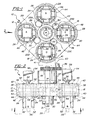
- Figure 1 is a bottom plan view of an article transfer station in one condition and taken along the plane of the line 1-1 of Figure 2, and looking in the direction of the arrows;
- Figure 2 is a side elevational view of the Figure 1
structure taken in the direction of the
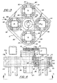
arrow 2 in Figure 1; - Figure 3 is a bottom plan view of a modified version of the article transfer station in that one condition and taken along the plane of the line 3-3 of Figure 4, and looking in the direction of the arrows;
- Figure 4 is a side elevational view in partial cross-section
of the Figure 3 structure and taken in the direction
of the
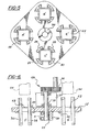
arrow 4 in Figure 3; and - Figures 5 and 6 are respective bottom plan and side elevational views illustrating the article transfer station in a condition different from that of either the Figures 1 and 2 or the Figures 3 and 4 versions.
-
- Referring now to the drawings in greater detail, Figures 1 and 2 illustrate a transfer station including a
rotary transfer device 10 including asupport member 12 rotatably mounted around a central fixedgear 14. Four equally spacedouter gears support member 12, outwardly of the central fixedgear 14. Anidler gear 23A is in mesh with the centralfixed gear 14 and the adjacentouter gear 22. Likewise, an idler gear 23B is in mesh with thegears idler gear 23C with thegears gears - Four equally spaced, vertically oriented
corner abutment members gear - As shown in Figure 2, the fixed
central gear 14 is secured bybolts 32 to amember 34. Thesupport member 12 is rotatably fixed to acentral shaft 35 driven by an external source, represented as 36. Amember 37 between thesupport 12 and drivesource 36 serves as a guide for theshaft 35 extending therethrough. Themember 12 is fixed to theshaft 35 by means of a C-clip 39 welded to themember 12 and fixed longitudinally of theshaft 35 by clampingscrews 31 and fixed peripherally of theshaft 35 by a key 33. - Each
outer gear cylindrical extensions lower bearings annular recesses 46 formed in thesupport member 12. Each lowercylindrical extension 40 has seated thereon aflange 48 formed around each set of fourcorner abutment members extension 40 by means ofscrews 41. - A chamfered
edge 52 is formed at each end of each of thecorner abutment members - While a single receiving pocket, say, A, may be selected in a particular application, in a preferred application, each of the pockets A and C receives a bottom-closed, thermoplastic-coated
carton 54 via stripper mechanisms represented as 56 in Figure 2, from respective mandrels, represented as 58, of a bottom forming turret, not shown here, but such as shown and described in U.S. Patent No. 4,590,740. - After being indexed 90° (during which the rolling of the
gears 16 to 22 causes the twocartons 54 in the pockets A and C to maintain their original orientation), the twocartons 54, now in the respective locations B and D in Figure 1, are pulled downwardly by any suitable additional stripper mechanisms, represented as 59 in Figure 2, similar to thestripper mechanism 56, out of their respective pockets onto a single line conveyor, represented as 60 in Figure 1, to thereafter be indexed through top filling, forming, and sealing stations, such as shown and described in the above referenced Patent No. 4,590,740. Concurrently, the pockets B and D, now in the respective positions shown as A and C, receive twoadditional cartons 54 from the next twomandrels 58. - Referring to the rotary transfer device 10a of Figures 3 and 4, it may be noted that a central
double width pulley 62 is used in lieu of thecentral gear 14, pulleys 80, 82, 84 and 86 are used in lieu of the fourouter gears belts idler gears 23A to 23D. Each belt is mounted around thecentral pulley 62 and around twoadjacent pulleys 80/82, and 84/86, which are rotatably mounted on thesupport 12. The fourcorner abutment members pulleys - The rotary transfer device 10b of Figures 5 and 6 differs from the
devices 10 and 10a of Figures 1 to 4 in that the gears of the Figures 1 and 2 embodiment, and the belts of the Figures 3 and 4 embodiment, are omitted, and the vertically orientedcorner abutment members rectangular openings 63 through a support member 12', in any suitable manner, for example (as shown) by thescrews 41 through theirflanges 48, directly to the support member 12', to provide respective receivers A', B', C' and D'. - As such, in the event that it is desired to rotate an article 90° on a machine, as opposed to maintaining the article's original angular orientation, the device 10b is substituted for the
device 10 or 10a, by loosening thescrews 31 of thedevice 10 or 10a, sliding thedevice 10 or 10a downwardly off theshaft 35, sliding the device 10b upwardly onto theshaft 35 and then tightening the clamping screws 31 of the device 10b to clamp it to the shaft. Accordingly, both the standard fifth panel cartons and the reverse fifth panel cartons (wherein the gable top closure panels are oriented 90° from those of the standard fifth panel carton, but must be conveyed through the downstream top filling, forming, and sealing in the same orientation) can be processed through the bottom-forming turret without any changes therein. - Thus, a packaging machine manufacturer can simply select either the
device 10 or 10a or the device 10b for fitting to a machine to be supplied to a package producer, depending upon whether the machine is to run standard fifth panel cartons or reverse fifth panel cartons, or can supply together with the machine both thedevice 10 or 10a and the device 10b, so that the producer can readily change the machine over from one style of carton to the other. - A possible alternative to having two different kinds of device 10 (or 10a) and 10b is that the
device 10 or 10a could have itsidler gears 23A to 23D, orbelts gears 16 to 22, or pulleys 80 to 86, fixable to therotary support member 12. The machine manufacturer can then send out the machine either with its idler gears or belts disengaged and its outer gears or pulleys fixed to the rotary support member, or with its idler gears or belts engaged and its outer gears or pulleys rotatable relative to the support member. Otherwise, the package producer can change-over the device from one condition to the other. - It should be apparent that the drawings illustrate a rotary transfer device for transferring cartons with no change in carton orientation.
- It should be further apparent that the receiver formed within each outer gear or ring could be formed in any desired shape other than the four corner abutment members, to accommodate a variety of carton shapes.
- It should be still apparent that, when desired, a selected one of the four receiver positions could be utilized, in lieu of two oppositely disposed positions, for transferring cartons one at a time to a conveyor, rather than in pairs.
- It should also be apparent that basically identical forming, filling and sealing machines, and their bottom forming turrets and
mandrels 58, can be configured to run the above referenced standard or reverse fifth panel cartons by installing appropriaterotary transfer devices 10, 10a, or 10b, for co-operation therewith.
Claims (19)
- An article transfer station for transferring articles (54) from a first conveyor (58) to a second conveyor (60), comprising means (10/10a, 10b, 31, 39) whereby the station can be selected to be either a station at which articles (54) are carried through a predetermined angle about a substantially vertical axis while changing their orientations by said angle, or a station at which articles (54) are carried through said predetermined angle about said axis without changing their orientations, said means (10/10a,10b,31,39) comprising a first device (10/10a) turnable about said axis and including first receivers (A-D) for receiving respective articles, and a mount (35) mounting said device (10/10a) and turnable about said axis, characterised by a connector (31,39) readily releasably connecting said device (10/10a) to said mount (35) and whereby said device (10/10a) can be disconnected from said mount (35) for replacement by a second device (10b) including second receivers (A'-D') for receiving respective articles.
- A station according to claim 1, wherein said connector (31,39) is readily releasably clamped around said mount (35).
- A station according to claim 1 or 2, and further comprising a central fixed member (14;62), said first device (10/10a) comprising a support member (12) turnable about said axis with said mount (35), and said first receivers (A-D) being rotatably mounted relative to said support member (12) while movable with said support member (12) and being operatively connected to the central fixed member (14;62) so as to be driven thereby.
- A station according to claim 3, wherein said central fixed member (14) is a gear, and said mount (35) comprises an externally driven member (35) extending axially through the central fixed gear (14), and said first receivers (A-D) comprise driven gears (16-22) in mesh with idler gears (23) of said first device (10) which, in turn, are in mesh with said central fixed gear (14).
- A station according to any preceding claim, wherein said second device (10b) comprises a second support member (12') turnable about said axis with said mount (35), said second receivers (A'-D') being fixed to said second support member (12').
- A station according to any preceding claim, wherein each of said receivers (A-D; A'-D') comprises article-holding members (24-30) distributed round the receiver (A-D; A'-D').
- A station according to claim 6, wherein said article-holding members (24-30) of each receiver (A-D; A'-D') are four substantially vertical corner guides (24-30).
- A station according to claim 7, wherein said four substantially vertical corner guides (24-30) each form a 90° receiving corner, with a chamfer (52) formed at an upper inlet edge of each guide (24-30) .
- A station according to any preceding claim, and further comprising loading means (56) for placing an article (54), or a pair of articles (54), in a selected one, or a selected pair, of said receivers (A-D; A'-D').
- A station according to any preceding claim, and further comprising unloading means (59) for removing an article (54), or a pair of articles (54), from each receiver or each pair of receivers (A-D; A'-D') and placing said article or said pair of articles (54) on said second conveyor (60).
- A station according to 9, or claim 10 as appended to claim 9, wherein said first conveyor (58) comprises mandrels (58) from which said loading means (56) serves to remove the articles (54).
- A method comprising selecting an article transfer station, for transferring articles (54) from a first conveyor (58) to a second conveyor (60), to be either a station at which articles (54) are carried through a predetermined angle about a substantially vertical axis while changing their orientations by said angle, or a station at which articles (54) are carried through said predetermined angle about said axis without changing their orientations, characterised in that said selecting comprises selecting to connect to a rotary mount (35) at the station either a first device (10/10a) including first article-receivers (A-D) rotatable relative to a first support member (12) included in said first device (10,10a), or a second device (10b) including second article-receivers (A'-D') fixed to a second support member (12') included in said second device (10b).
- A station according to claim 1, and including a central fixed member (14;62), and a device (10,10a) turnable about said axis and comprising a support member (12), receivers (A-D) for receiving respective cartons (54) and rotatably mounted relative to said support member (12), and said means (23A-23D, 16-22; 64,66,80-86), said means (23A-23D, 16-22; etc.) disconnectably connecting said central fixed member (14;62) to said receivers (A-D) for rotating said receivers (A-D) relative to said central fixed member (14;62).
- A method, characterised by selecting a carton transfer station, for transferring cartons (54) from a first conveyor (58) to a second conveyor (60), to be either a station at which cartons (54) are carried through a predetermined angle about a substantially vertical axis while changing their orientations by said angle, or a station at which cartons (54) are carried through said predetermined angle about said axis without changing their orientations.
- A method according to claim 14, wherein said selecting comprises selecting to connect to a rotary mount (35) at the station either a first device (10/10a) including first carton-receivers (A-D) rotatable relative to a first support member (12) included in said first device (10,10a), or a second device (10b) including second carton-receivers (A'-D') fixed to a second support member (12') included in said second device (10b).
- A method according to claim 14, wherein said selecting comprises disconnecting from a rotary drive (35) at the station one of a first device (10/10a) including first carton-receivers (A-D) rotatable relative to a first support member (12) included in said first device (10/10a) and a second device (10b) including second carton-receivers (A'-D') fixed to a second support member (12') included in said second device (10b) and replacing said one of said first device (10/10a) and said second device (10b) by the other of said first device (10/10a) and said second device (10b).
- A method according to claim 14, wherein said selecting comprises selectively disconnecting and connecting drive elements (23A-23D; 64,66) between a fixed central member (14;62) and carton-receivers (A-D) rotatably carried by a support member (12) turnable about said fixed central member (14;62).
- An article transfer station for transferring articles (54) from a first conveyor (58) to a second conveyor (60), comprising means (10/10a, 10b, 31, 39) means whereby the station can be selected to be either a station at which articles (54) are carried through a predetermined angle about a substantially vertical axis while changing their orientations by said angle, or a station at which articles (54) are carried through said predetermined angle about said axis without changing their orientations, said means (10/10a,10b,31,39) comprising a first device (10/10a) turnable about said axis and including first receivers (A-D) for receiving respective articles, and a mount (35) mounting said device (10/10a) and turnable about said axis, characterised by a connector (31,39) readily releasably connecting said device (10/10a) to said mount (35) and whereby said device (10/10a) can be disconnected from said mount (35) for replacement by a second device (10b) including second receivers (A'-D') for receiving respective articles.
- A method comprising selecting an article transfer station, for transferring articles (54) from a first conveyor (58) to a second conveyor (60), to be either a station at which articles (54) are carried through a predetermined angle about a substantially vertical axis while changing their orientations by said angle, or a station at which articles (54) are carried through said predetermined angle about said axis without changing their orientations, characterised in that said selecting comprises selecting to connect to a rotary mount (35) at the station either a first device (10/10a) including first article-receivers (A-D) rotatable relative to a first support member (12) included in said first device (10,10a), or a second device (10b) including second article-receivers (A'-D') fixed to a second support member (12') included in said second device (10b).
Applications Claiming Priority (2)
| Application Number | Priority Date | Filing Date | Title |
|---|---|---|---|
| US766992 | 1996-12-16 | ||
| US08/766,992 US5927474A (en) | 1996-12-16 | 1996-12-16 | Rotary transfer station |
Publications (2)
| Publication Number | Publication Date |
|---|---|
| EP0847945A1 EP0847945A1 (en) | 1998-06-17 |
| EP0847945B1 true EP0847945B1 (en) | 2004-09-22 |
Family
ID=25078146
Family Applications (1)
| Application Number | Title | Priority Date | Filing Date |
|---|---|---|---|
| EP97309777A Expired - Lifetime EP0847945B1 (en) | 1996-12-16 | 1997-12-04 | Article transfer station |
Country Status (4)
| Country | Link |
|---|---|
| US (1) | US5927474A (en) |
| EP (1) | EP0847945B1 (en) |
| JP (1) | JPH10181852A (en) |
| DE (1) | DE69730805T2 (en) |
Cited By (1)
| Publication number | Priority date | Publication date | Assignee | Title |
|---|---|---|---|---|
| DE102005021831A1 (en) * | 2005-05-11 | 2006-11-23 | Mühlbauer Ag | Device for transporting platelets |
Families Citing this family (8)
| Publication number | Priority date | Publication date | Assignee | Title |
|---|---|---|---|---|
| US7059466B2 (en) * | 2004-01-23 | 2006-06-13 | Tetra Laval Holdings & Finance, Sa | Carton transfer unit |
| DE102008056797A1 (en) * | 2008-11-11 | 2010-05-12 | Kmk Lizence Ltd. | Device and method for producing tubes |
| IT1402328B1 (en) * | 2010-10-15 | 2013-08-30 | I P S S R L Internat Project Services | "PLASTIC BAG PACKAGE DEVICE" |
| CN102079400B (en) * | 2010-11-27 | 2012-05-23 | 中国兵器工业集团第五二一研究所 | Design method for mechanical drive bag pushing mechanism |
| US10524980B2 (en) * | 2016-09-13 | 2020-01-07 | Vanrx Pharmasystems, Inc. | Apparatus and method for aseptically filling pharmaceutical containers with a pharmaceutical fluid using rotary stage |
| CN105329660B (en) * | 2015-12-03 | 2017-10-10 | 江苏海阳化纤有限公司 | A kind of annular stepping type feeding-distribution device |
| CN108891662B (en) * | 2018-05-23 | 2020-12-11 | 泉州台商投资区新克力新材料有限公司 | Automatic cash register for supermarket |
| CN111453357A (en) * | 2020-03-17 | 2020-07-28 | 大族激光科技产业集团股份有限公司 | Steering mechanism and battery module production system |
Family Cites Families (14)
| Publication number | Priority date | Publication date | Assignee | Title |
|---|---|---|---|---|
| US26656A (en) * | 1860-01-03 | Improvement in cultivators | ||
| US1431930A (en) * | 1921-06-06 | 1922-10-17 | Horace L Campbell | Elevator |
| US3868009A (en) * | 1973-03-29 | 1975-02-25 | Carle & Montanari Spa | Transferring device |
| US4066162A (en) * | 1975-11-28 | 1978-01-03 | Harris Corporation | Orbital turn |
| US4337059A (en) * | 1979-06-25 | 1982-06-29 | Allen Robert J | Carton bottom tucking and tacking apparatus with pivotal tucker wings for packaging machines |
| US4311476A (en) * | 1979-07-18 | 1982-01-19 | Williams Eric A | Method and apparatus for forming a container for liquids |
| IT1172096B (en) * | 1981-11-24 | 1987-06-18 | Gd Spa | DEVICE FOR THE CONVEYING OF CIGARETTES SPEZES A DOUBLE EACO CIGARETTE PACKAGING MACHINE TO A FILTER FEEDER MACHINE |
| DE3245539A1 (en) * | 1982-12-09 | 1984-06-14 | Agfa-Gevaert Ag, 5090 Leverkusen | DEVICE IN A PHOTOGRAPHIC COPIER FOR RECORDING AND TRANSPORTING FILM UNITS |
| US4590740A (en) * | 1983-07-15 | 1986-05-27 | Ex-Cell-O Corporation | Container sterilization apparatus and method |
| GB8819573D0 (en) * | 1988-08-17 | 1988-09-21 | Elopak Systems | Packaging |
| US5029695A (en) * | 1990-04-03 | 1991-07-09 | S. C. Johnson & Son, Inc. | Improved starwheel |
| DE4117296C2 (en) * | 1991-05-27 | 2002-11-21 | Winkler & Duennebier Ag | Device for transferring objects |
| IT1253889B (en) * | 1991-11-19 | 1995-08-31 | Azionaria Costruzioni Acma Spa | METHOD AND DEVICE FOR THE STEP-BY-STEP TRANSFER OF PRODUCTS TO A WRAPPING LINE |
| DE19513411A1 (en) * | 1995-04-08 | 1996-10-10 | Magdeburg Getraenkemasch | Device for arranging transport star, for bottles handling unit |
-
1996
- 1996-12-16 US US08/766,992 patent/US5927474A/en not_active Expired - Fee Related
-
1997
- 1997-12-04 DE DE69730805T patent/DE69730805T2/en not_active Expired - Lifetime
- 1997-12-04 EP EP97309777A patent/EP0847945B1/en not_active Expired - Lifetime
- 1997-12-16 JP JP9364063A patent/JPH10181852A/en active Pending
Cited By (1)
| Publication number | Priority date | Publication date | Assignee | Title |
|---|---|---|---|---|
| DE102005021831A1 (en) * | 2005-05-11 | 2006-11-23 | Mühlbauer Ag | Device for transporting platelets |
Also Published As
| Publication number | Publication date |
|---|---|
| JPH10181852A (en) | 1998-07-07 |
| DE69730805D1 (en) | 2004-10-28 |
| DE69730805T2 (en) | 2006-02-23 |
| EP0847945A1 (en) | 1998-06-17 |
| US5927474A (en) | 1999-07-27 |
Similar Documents
| Publication | Publication Date | Title |
|---|---|---|
| JP4699602B2 (en) | Container packaging apparatus and packaging method | |
| KR101207387B1 (en) | System and method for packaging oriented containers | |
| AU2005282599B2 (en) | Packaging system having loading carousel | |
| EP0847945B1 (en) | Article transfer station | |
| EP0707550B1 (en) | Methods for conveying objects through apparatus, packing apparatus and methods for packing materials in cartons | |
| US10611509B2 (en) | Systems and methods for forming and labeling containers | |
| EP0819611B1 (en) | Container fitment application | |
| US7162852B2 (en) | Device for filling stand-alone flat-bottom bags | |
| CA3113292C (en) | Method and system for conveying articles | |
| CN114206732B (en) | Wheeled conveyor for conveying containers, machine and method for applying flexible carriers to a plurality of containers | |
| US6050062A (en) | Multiple magazine for a packaging machine | |
| EP1352835A2 (en) | Device for transferring articles and wrapping machine comprising such a device | |
| EP1028894B1 (en) | Carton blank erecting mechanism | |
| EP0355063B1 (en) | Packaging | |
| WO2024135113A1 (en) | Pouch supply device, pouch supply method, and filling system | |
| WO2022072608A1 (en) | Packaging machine for packaging products or product groups, and method for operating such a packaging machine | |
| WO2024055025A1 (en) | Systems and methods for packaging articles in a carton | |
| EP0161784B1 (en) | Drop-loading packaging machine | |
| WO2023048563A1 (en) | A system for processing containers during transport | |
| WO2000064739A2 (en) | Multiple magazine for a packaging machine | |
| JPH1179368A (en) | Aligning device for objects to be conveyed | |
| JP2002527318A (en) | Equipment for product transfer, counting and loading |
Legal Events
| Date | Code | Title | Description |
|---|---|---|---|
| PUAI | Public reference made under article 153(3) epc to a published international application that has entered the european phase |
Free format text: ORIGINAL CODE: 0009012 |
|
| AK | Designated contracting states |
Kind code of ref document: A1 Designated state(s): DE GB IT SE |
|
| AX | Request for extension of the european patent |
Free format text: AL;LT;LV;MK;RO;SI |
|
| 17P | Request for examination filed |
Effective date: 19981127 |
|
| AKX | Designation fees paid |
Free format text: DE GB IT SE |
|
| RBV | Designated contracting states (corrected) |
Designated state(s): DE GB IT SE |
|
| 17Q | First examination report despatched |
Effective date: 20021227 |
|
| GRAP | Despatch of communication of intention to grant a patent |
Free format text: ORIGINAL CODE: EPIDOSNIGR1 |
|
| GRAS | Grant fee paid |
Free format text: ORIGINAL CODE: EPIDOSNIGR3 |
|
| GRAA | (expected) grant |
Free format text: ORIGINAL CODE: 0009210 |
|
| AK | Designated contracting states |
Kind code of ref document: B1 Designated state(s): DE GB IT SE |
|
| REG | Reference to a national code |
Ref country code: GB Ref legal event code: FG4D |
|
| REF | Corresponds to: |
Ref document number: 69730805 Country of ref document: DE Date of ref document: 20041028 Kind code of ref document: P |
|
| REG | Reference to a national code |
Ref country code: SE Ref legal event code: TRGR |
|
| REG | Reference to a national code |
Ref country code: GB Ref legal event code: 727 |
|
| PLBE | No opposition filed within time limit |
Free format text: ORIGINAL CODE: 0009261 |
|
| STAA | Information on the status of an ep patent application or granted ep patent |
Free format text: STATUS: NO OPPOSITION FILED WITHIN TIME LIMIT |
|
| 26N | No opposition filed |
Effective date: 20050623 |
|
| REG | Reference to a national code |
Ref country code: GB Ref legal event code: 727A |
|
| REG | Reference to a national code |
Ref country code: GB Ref legal event code: 727H |
|
| PGFP | Annual fee paid to national office [announced via postgrant information from national office to epo] |
Ref country code: SE Payment date: 20091214 Year of fee payment: 13 |
|
| PGFP | Annual fee paid to national office [announced via postgrant information from national office to epo] |
Ref country code: IT Payment date: 20091222 Year of fee payment: 13 Ref country code: GB Payment date: 20091218 Year of fee payment: 13 |
|
| PGFP | Annual fee paid to national office [announced via postgrant information from national office to epo] |
Ref country code: DE Payment date: 20091222 Year of fee payment: 13 |
|
| GBPC | Gb: european patent ceased through non-payment of renewal fee |
Effective date: 20101204 |
|
| REG | Reference to a national code |
Ref country code: SE Ref legal event code: EUG |
|
| PG25 | Lapsed in a contracting state [announced via postgrant information from national office to epo] |
Ref country code: SE Free format text: LAPSE BECAUSE OF NON-PAYMENT OF DUE FEES Effective date: 20101205 |
|
| REG | Reference to a national code |
Ref country code: DE Ref legal event code: R119 Ref document number: 69730805 Country of ref document: DE Effective date: 20110701 |
|
| PG25 | Lapsed in a contracting state [announced via postgrant information from national office to epo] |
Ref country code: DE Free format text: LAPSE BECAUSE OF NON-PAYMENT OF DUE FEES Effective date: 20110701 Ref country code: GB Free format text: LAPSE BECAUSE OF NON-PAYMENT OF DUE FEES Effective date: 20101204 |
|
| PG25 | Lapsed in a contracting state [announced via postgrant information from national office to epo] |
Ref country code: IT Free format text: LAPSE BECAUSE OF NON-PAYMENT OF DUE FEES Effective date: 20101204 |