EP0847831B1 - Procédé de fabrication de fils fourrés étanches pour le soudage à l'arc - Google Patents
Procédé de fabrication de fils fourrés étanches pour le soudage à l'arc Download PDFInfo
- Publication number
- EP0847831B1 EP0847831B1 EP98400277A EP98400277A EP0847831B1 EP 0847831 B1 EP0847831 B1 EP 0847831B1 EP 98400277 A EP98400277 A EP 98400277A EP 98400277 A EP98400277 A EP 98400277A EP 0847831 B1 EP0847831 B1 EP 0847831B1
- Authority
- EP
- European Patent Office
- Prior art keywords
- tube
- gaseous
- flux
- cored wire
- sealed
- Prior art date
- Legal status (The legal status is an assumption and is not a legal conclusion. Google has not performed a legal analysis and makes no representation as to the accuracy of the status listed.)
- Expired - Lifetime
Links
Images


Classifications
-
- B—PERFORMING OPERATIONS; TRANSPORTING
- B23—MACHINE TOOLS; METAL-WORKING NOT OTHERWISE PROVIDED FOR
- B23K—SOLDERING OR UNSOLDERING; WELDING; CLADDING OR PLATING BY SOLDERING OR WELDING; CUTTING BY APPLYING HEAT LOCALLY, e.g. FLAME CUTTING; WORKING BY LASER BEAM
- B23K35/00—Rods, electrodes, materials, or media, for use in soldering, welding, or cutting
- B23K35/40—Making wire or rods for soldering or welding
-
- B—PERFORMING OPERATIONS; TRANSPORTING
- B23—MACHINE TOOLS; METAL-WORKING NOT OTHERWISE PROVIDED FOR
- B23K—SOLDERING OR UNSOLDERING; WELDING; CLADDING OR PLATING BY SOLDERING OR WELDING; CUTTING BY APPLYING HEAT LOCALLY, e.g. FLAME CUTTING; WORKING BY LASER BEAM
- B23K35/00—Rods, electrodes, materials, or media, for use in soldering, welding, or cutting
- B23K35/40—Making wire or rods for soldering or welding
- B23K35/406—Filled tubular wire or rods
-
- B—PERFORMING OPERATIONS; TRANSPORTING
- B23—MACHINE TOOLS; METAL-WORKING NOT OTHERWISE PROVIDED FOR
- B23K—SOLDERING OR UNSOLDERING; WELDING; CLADDING OR PLATING BY SOLDERING OR WELDING; CUTTING BY APPLYING HEAT LOCALLY, e.g. FLAME CUTTING; WORKING BY LASER BEAM
- B23K35/00—Rods, electrodes, materials, or media, for use in soldering, welding, or cutting
- B23K35/40—Making wire or rods for soldering or welding
- B23K35/406—Filled tubular wire or rods
- B23K2035/408—Filled tubular wire or rods with welded longitudinal seam
-
- B—PERFORMING OPERATIONS; TRANSPORTING
- B23—MACHINE TOOLS; METAL-WORKING NOT OTHERWISE PROVIDED FOR
- B23K—SOLDERING OR UNSOLDERING; WELDING; CLADDING OR PLATING BY SOLDERING OR WELDING; CUTTING BY APPLYING HEAT LOCALLY, e.g. FLAME CUTTING; WORKING BY LASER BEAM
- B23K35/00—Rods, electrodes, materials, or media, for use in soldering, welding, or cutting
- B23K35/22—Rods, electrodes, materials, or media, for use in soldering, welding, or cutting characterised by the composition or nature of the material
- B23K35/38—Selection of media, e.g. special atmospheres for surrounding the working area
-
- B—PERFORMING OPERATIONS; TRANSPORTING
- B23—MACHINE TOOLS; METAL-WORKING NOT OTHERWISE PROVIDED FOR
- B23K—SOLDERING OR UNSOLDERING; WELDING; CLADDING OR PLATING BY SOLDERING OR WELDING; CUTTING BY APPLYING HEAT LOCALLY, e.g. FLAME CUTTING; WORKING BY LASER BEAM
- B23K35/00—Rods, electrodes, materials, or media, for use in soldering, welding, or cutting
- B23K35/22—Rods, electrodes, materials, or media, for use in soldering, welding, or cutting characterised by the composition or nature of the material
- B23K35/38—Selection of media, e.g. special atmospheres for surrounding the working area
- B23K35/383—Selection of media, e.g. special atmospheres for surrounding the working area mainly containing noble gases or nitrogen
Definitions
- the invention relates to a method of manufacturing a waterproof welded metal tube or wire containing elements of filling, a sealed flux-cored wire, and a welding process using such a sealed cored wire, as well as a weld that can be obtained by placing welding process.
- Welding cored wires are conventionally made up of at least a tubular external metallic envelope filled with elements of filling in the form of powder and / or particles, in particular of a nature metallic and / or mineral and / or organic.
- elements of filling one or more identical or different constituents, likewise nature and / or different natures, in the form of powder and / or particles and / or in any other similar agglomerated form, such as filling of cored welding wires for example.
- Crimped cored tubes or wires are characterized by a cross section more or less complex geometry and by a non-tight longitudinal joint resulting from crimping of the two longitudinal edges of the sheet metallic forming the outer tubular envelope of the tube, with each other.
- sealed welded cored tubes or wires are characterized by the presence of a tight longitudinal joint resulting from welding one to the other, of the two longitudinal edges of said metal sheet.
- sealed welded cored tubes or wires have several advantages compared to crimped tubes or cored wires.
- waterproof cored tubes or wires can be stored more easily and longer, since the risk of recovery humidity of the content of said cored tubes or wires, that is to say elements filling, is very low given the tightness of said tubes, this which guarantees a very low diffusible hydrogen content in the metal deposited and therefore minimize the risk of cold cracking of welded joints obtained.
- the longitudinal edges of said pre-tube or pre-wire are united one to the other by welding, for example high-frequency or multicathode welding, so as to obtain a sealed vacuum tube or wire, which can be then rolled and / or drawn to a predefined diameter, generally a function of the formula of the cored wire to be manufactured.
- the sealed vacuum tube or wire thus obtained is then filled with elements of filling by vibration by means of a vibrating table.
- elements of filling by vibration by means of a vibrating table.
- constituents in agglomerated form such as granules, are preferred.
- the waterproof tube or wire filled with filling elements can be rolled and / or drawn to an intermediate diameter where it then undergoes a recrystallization annealing operation necessary to continue without rupture, the drawing of said cored wire to its final diameter.
- the tube or cored wire thus obtained can optionally be subjected to copper plating exterior as mentioned above.
- filling elements in granular form and / or powdery, are introduced directly into the shaped metal sheet gutter, which is then given an "O" shape by edge-to-edge joining together of its two longitudinal edges.
- the non-welded pre-tube or pre-wire filled with filling flux as well obtained is then welded so as to constitute a sealed cored tube, which can then undergo the above-mentioned drawing operations, rolling, annealing, drawing and / or copper plating, as in the previous case.
- the air atmospheric, and therefore in particular the nitrogen found there, initially present between said constituents of the filling flow is evacuated across the longitudinal crimp joint, which joint is never fully waterproof. It follows that the nitrogen content of the resulting cored wire is then approximately equal to the sum of the nitrogen contents of the various constituents of the cored wire, namely the filling flow and the envelope external, weighted by their respective quantities.
- the presence of air can be particularly harmful for the welding to be performed, since at least part of the air gases, in particular nitrogen will end up in the deposited metal, i.e. the gasket solder, and degrade its mechanical properties.
- the document US-A-4,673,121 describes a continuous manufacturing process for a powder-coated tubular welding electrode in which the air is evacuated from the empty tube, then a powder is introduced into the tube while being mixed with a protective gas. According to this process, the powder contains a porous inorganic material having good absorbability of gas.
- EP-A-0136276 relates to a process for the continuous production of an electrode tubular welding from a gutter-shaped pre-tube, in which a powder is introduced into the pre-tube and the longitudinal edges of said pre-tube are welded together, the welding being carried out under a protective gas atmosphere, for example carbon dioxide.
- the Japanese abstract vol. 007, no. 269 (M-259), November 30, 1983 & JP-A-58148096 relates to a process for manufacturing flux-cored wire, in which the nitrogen contained in the wire is evacuated by vacuum pumping, then the tube is filled with a powder and then with argon or carbon dioxide.
- JP-A-03198997 & JP-A- 03198998 relate to a process for manufacturing cored wire welding, in which the nitrogen contained in the wire is eliminated by means of a inert gas.
- the present invention therefore aims to solve even more effectively the problem untimely and undesirable entrapment of atmospheric air in sealed welded tubes filled with filling elements, such as wires sealed welding cores and therefore, by this, to improve the mechanical properties of solder joints made by welding by means of such cored wires.
- the aim of the present invention is to propose, on the one hand, a method of manufacturing welded tubes watertight with filling elements, such as watertight cored wires welding, making it possible to avoid or minimize the quantity of some of the impurities or harmful elements contained in trapped atmospheric air in the tubes themselves and / or in the filling streams therein introduced, and, on the other hand, sealed welded flux cores containing proportions of harmful gaseous impurities, in particular nitrogen gas, significantly lower than those contained in the cored wires of art prior.
- filling elements such as watertight cored wires welding
- the present invention therefore relates, according to a first aspect, to a method of manufacturing at least one sealed welded metal tube containing filling elements according to claim 1.
- the present invention is based on the implementation contact of the filling elements with a poor atmosphere or depleted in harmful gaseous atmospheric compounds, such in particular atmospheric nitrogen and / or humidity.
- the invention also relates to a cored wire waterproof, that is to say a cored wire whose two longitudinal edges are joined by welding with each other, capable of being obtained by a aforementioned manufacturing process, in particular a sealed flux-cored wire comprising at least one metal casing and a filling flow containing filling elements, the cored wire containing a total nitrogen content less than 100 ppm, preferably less than 80 ppm, preferably less than 70 ppm, preferably less than 60 ppm, preferably less than 55 ppm and preferably less than 50 ppm.
- total proportion of nitrogen means the sum of the quantities of nitrogen gas and non-gaseous contained or incorporated in the cored wire.
- the total proportion of nitrogen contained in the metallic envelope and in said filling flow of said cored wire is equal to at least about 60% of the total proportion of nitrogen contained in said wire, preferably at least about 70%.
- the sealed cored wire is substantially free nitrogen gas, preferably completely free of nitrogen gas.
- the waterproof cored wire contains nitrogen molecules gaseous and at least one second gas, the proportion of molecules of said second gas in the cored wire being greater than the proportion of molecules nitrogen gas in said cored wire.
- the second gas is chosen from argon, carbon dioxide, oxygen and helium, preferably the second gas is argon or carbon dioxide.
- the sealed flux-cored wire contains nitrogen gas molecules and oxygen gas molecules, the ratio of the proportion of nitrogen gas molecules in the cored wire to the proportion of gaseous oxygen molecules in said cored wire being less than 4, of preferably less than 3.5, preferably less than 2.5.
- the invention also relates to an arc welding process.
- a waterproof cored wire according to the invention preferably an arc welding process chosen from TIG welding processes (Tungsten Inert Gas), MIG (Metal Inert Gas), MAG (Metal Active Gas) and the submerged arc, and a weld bead capable of being obtained by implementation of such an arc welding process, which bead of solder is characterized in that it contains less than 60 ppm nitrogen, preferably even less than 50 ppm nitrogen.
- weld bead is meant the metal deposited, preferably cooled, obtained by melting at least part of said cored wire.
- the inventive method provides recover, recycle and / or purify the gaseous atmosphere of protection which allows to use a lesser amount of gas and therefore to decrease the overall costs of the manufacturing process.
- the purification of said gaseous atmosphere in its impurities can be done by known means skilled in the art, for example by means of membrane modules, suitable adsorbents and / or catalysts, such as those used in particular in gas purification processes, for example air purification before cryogenic distillation.
- the gas or gas mixture constituting the atmosphere protective gas used in the context of the present invention can be from any gas source known to those skilled in the art, that is to say a packaging (gas cylinder, storage capacity «) or a pipeline, or a gas production source that can be located on the same manufacturing site, for example a type of production unit PSA (for pressure swing adsorption), a unit with membrane modules, or any other cryogenic or non-cryogenic gas separation unit known to those skilled in the art.
- a packaging gas cylinder, storage capacity «
- a pipeline or a gas production source that can be located on the same manufacturing site, for example a type of production unit PSA (for pressure swing adsorption), a unit with membrane modules, or any other cryogenic or non-cryogenic gas separation unit known to those skilled in the art.
- PSA for pressure swing adsorption
- membrane modules for cryogenic or non-cryogenic gas separation unit known to those skilled in the art.
- This entire manufacturing process is carried out in air atmospheric and at atmospheric pressure.
- This manufacturing process using the OERLIKON TM technique is also performed, in its entirety, at atmospheric air and at pressure atmospheric.
- This manufacturing process is also carried out, in its entirety, at atmospheric air and at atmospheric pressure.
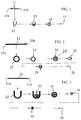
- FIG. 7 represents, for its part, a diagram of a first mode of realization of a manufacturing method according to the present invention of tubes or sealed welded flux cored wires, from a metal sheet 71, shown schematically in cross section, which is first given a shape of gutter 72 in "U" as explained above.
- Filling elements 73 are then introduced into the gutter 72, said introduction being carried out in an inerted area 80, that is to say in an area where the gaseous atmosphere is controlled, so as to avoid and / or minimize any contact and / or introduction of gaseous pollutants undesirable, such as nitrogen, hydrogen and / or water vapor, in the tube and / or in contact and / or in the filling elements 73, such as a flow of filling for cored wires.
- gaseous pollutants undesirable such as nitrogen, hydrogen and / or water vapor
- Welding of the longitudinal joint of the tube is carried out, like filling, in the inerted zone 80, for example by means of a casing into which is introduced a protective gas flow, such as a flow of argon or CO 2 , or an Ar / CO 2 , Ar / O 2 or Ar / CO 2 / O 2 mixture, substantially free of impurities or containing only a small proportion of impurities, for example at most a few%, ppm or ppb of nitrogen , hydrogen and / or water vapor.
- a protective gas flow such as a flow of argon or CO 2 , or an Ar / CO 2 , Ar / O 2 or Ar / CO 2 / O 2 mixture, substantially free of impurities or containing only a small proportion of impurities, for example at most a few%, ppm or ppb of nitrogen , hydrogen and / or water vapor.
- the inerted zone 80 can also be a zone set at least partial vacuum in order to extract at least part of the impurities, in particular nitrogen, hydrogen and / or moisture, which it contains, which is either at least partially repressurized with a protective gas flow, such as argon.
- a protective gas flow such as argon.
- air purified i.e. air from which impurities have been removed beforehand harmful to the production of a cored wire according to the invention which it contains, such nitrogen, hydrogen and / or humidity; this can be done by purification known to those skilled in the art.
- the tube 74 is rolled and / or drawn. sealed welded and filled with filling elements up to a diameter lower 75 intermediate.
- the manufacturing process according to the present invention implements a protective gas atmosphere with physicochemical characteristics are carefully controlled within the inerted zone 80, such a protective cover, so as to avoid or minimize any harmful incorporation of gaseous impurities, in particular nitrogen atmospheric, in waterproof tubes thus manufactured, such as cored wires welding.
- Figures 4 and 5 show diagrams of two installations for manufacturing a metal tube, here a wire 50 sealed welding flux, from an empty sealed tube, in which are introduced filling elements, here a filling flow, by the bias of filling means comprising joining means, such a pipe 42, and a hopper 44 or filling flow tank, allowing the introduction of said filling flow into said wound wire 50 on a reel 40.
- an at least partial vacuum is made inside the wire 50 prior to the introduction of the flow of filling therein, so as to extract at least one waterproof wire part of the molecules of undesirable gaseous compounds found there, mainly atmospheric nitrogen.
- Vacuuming is carried out by at least one but, of preferably, the two ends of the wire 50, by means 48 of setting vacuum (non-detailed) of conventional type, comprising in particular one or more vacuum pumps, valves, gas lines, seals sealing, a reservoir 68 to recover the excess powders at the outlet of the tube 50 ...
- one also performs, at least temporarily, a at least partial evacuation of the hopper or reservoir 44 containing the flow filling and / or line 42, so as to purge them from a at least part of the atmospheric air therein, before the start of the filling the wire 50.
- filling the sealed welded wire 50 is produced by vibration, in known manner, the vacuum being maintained for at least minus part of this operation.
- pumping or vacuum produced by pumping means 48 is stopped and the pressure is gradually restored by introducing the shielding gas chosen, for example argon, via valve 46, until the atmospheric pressure in particular at the reservoir 68 of recovery of excess powder.
- a gas filling such as a flow of argon
- a gas filling is introduced by the valve 46 into the hopper 44, said filling gas making it possible to produce and maintenance of a protective gas atmosphere in the hopper or tank 44, the pipe 42 and / or in the sealed welded wire 50 and, by elsewhere, to favor the filling of the wire 50 with the filling flow in promoting the routing of said filling flow from the hopper 44 to the wire 50 through line 42.
- the circulation and distribution of the filling flow in the wire 50 are provided, in a manner known to those skilled in the art, by a table vibrator 43 on which the coil 40 is installed.
- Figure 5 is similar to that of Figure 4, except that in this case partial vacuuming is replaced by a purge, prior to any filling of the wire 50, with air located inside the hopper 44, the pipe 42 and the wire 50.
- This purge is carried out by ensuring a gaseous sweep of these by a protective gas, that is to say a gas flow of composition controlled, such as a flow of argon and / or carbon dioxide, said gas protection being introduced 46, 86 (not detailed) at the hopper 44 and / or at line 42 via valve 45.
- a protective gas that is to say a gas flow of composition controlled, such as a flow of argon and / or carbon dioxide
- the wire 50 After elimination of all or part of the trapped air, in particular in the wire 50, the wire 50 is filled with the elements of filling and under protective gas atmosphere, as in the case previous.
- Figure 6 shows another installation industrial and continuous manufacturing, in which part of the wire 60 is subjected to a gaseous protective sweep with a nitrogen-free gas, such as an argon stream.
- a gaseous protective sweep with a nitrogen-free gas such as an argon stream.
- the cored wire 60 is manufactured continuously, that is to say that the wire 60 is driven at a non-zero speed according to a translational movement, the wire 60 being driven, so conventional, by means of drive rollers or the like, for example (not detailed here).
- the filling of the wire 60 with the flow of filling and / or sealing of the two longitudinal edges 60a and 60b of the wire 60 are produced under an atmosphere having a nitrogen content controlled, preferably nitrogen-free, to avoid or minimize the amount of nitrogen incorporated in said cored wire.
- one or more gas injectors 62 are arranged way to send a shielding gas, such as argon, over the flow of filling, inside the welded cored wire 60 and / or around the area 61 to create a protective gas atmosphere. More specifically, this injection of protective gas is carried out, by the downstream end 88 of the injector 62, at the injection zone 89 located inside the tube 60 downstream of the welding zone 61 of said tube 60; the injector 62 being supplied with argon by supply means 81 gas of conventional type (not detailed) which may include gas pipes, seals, a storage tank ...
- a shielding gas such as argon
- the injector 62 and the welding means are fixed, while the tube 60 moves in translation, so that the different stages (forming in “U”, then in “O”, welding ...) leading to the waterproof cored wire formation are carried out continuously.
- Figures 8 and 9 show, respectively, sectional views transverse of Figure 6 at the lines AA and BB.
- Figure 9 shows a view of the wire in the form of "U", after introduction of the filling elements 73 and before welding longitudinal edges of the metal sheet 66, with each other, and the 8 shows a view of the wire 60 after introduction of the elements of filling 73 and after welding the longitudinal edges of the sheet metal 66, so as to obtain a tight flux-cored wire 65.
- the introduction of the protective gas, such as argon by the downstream end 88 of the injector 62 is produced inside the welded wire, so as to expel said cored wire from the air and therefore the impurities which are there, especially atmospheric nitrogen.
- a cored wire is thus obtained in accordance with the present invention, i.e. containing substantially no atmospheric nitrogen or other unwanted impurities.
- the manufacturing process of FIG. 6 is a continuous process, in which the wire 60 is subjected to a translational movement by known type of drive means allowing a production of wire stuffed on an industrial scale.
- a crimped cored wire (FF1A) by means of the process of FIG. 1 and, on the other hand, a wire waterproof welded thicket (FF1B) using the method of Figure 2 (Oerlikon technique).
- This powder mixture comprises rutile (TiO 2 ) as the majority compound, slag-forming elements, such as Al 2 O 3 and ZrSiO 4 , alloying elements, such as those of the Fe-Mn or Si-Mn type, and deoxidizing elements, such as Al, Al-Mg ...
- the filling rate or weight flow / weight weight ratio is, in the two cases, about 15%.
- Example 3 The fill stream from Example 1 was used, as previously, to manufacture, on the one hand, a crimped cored wire (FF2A), as in Example 1, by means of the method of FIG. 1 and, on the other hand, a wire waterproof welded thicket (FF2B) using the method of Figure 3.
- FF2A crimped cored wire
- FF2B wire waterproof welded thicket
- the filling rate or weight flow / weight weight ratio is, in the two cases, around 16.2%.
- Example 2 The results obtained are analogous to those of Example 1 and confirm the incorporation of a significant amount of nitrogen present in atmospheric air in tight cored wires produced according to prior art methods.
- the first cored wire (FF3A) was filled with flux by vibration according to the classic Oerlikon technique shown in Figure 2.
- the second cored wire (FF3B) was also filled with flux by vibration.
- the interior of this second cored wire, the hopper containing the filling powders and the supply means (pipes, etc.) connecting said hopper inside said wire thickets have been subjected to successively depressurization, i.e. vacuum, to extract most of the air atmospheric (therefore nitrogen) which was there, then subjected to a sweep purge by a flow of argon introduced into the hopper, as well as shown schematically in Figure 4, that is to say in accordance with this invention.
- the first cored wire (FF4A) was filled with flux by vibration according to the classic Oerlikon technique shown in Figure 2.
- the second cored wire (FF4B) was filled with flux by vibration, analogous to the cored wire No. FF3B of Example 3, that is to say in subjecting the sealed vacuum wire to a vacuum followed by a purge sweep by argon flow, in accordance with this invention.
- the third cored wire (FF4C) was filled like the second cored wire (FF4B), but with purge sweep by a flow of carbon dioxide (CO 2 ), in accordance with the present invention.
- the first cored wire (FF5A) was manufactured by injecting argon gas in the tube above the filling elements at the welding area to minimize the amount of atmospheric air trapped in the tube after tight welding, as shown diagrammatically on Figures 6, 8 and 9.
- the second cored wire (FF5B) was manufactured by injecting argon gas in an inert area or inerting box surrounding the machine forming / filling / welding, from the filling area to the tube welding area, as shown schematically in Figure 7.
- This example aims to compare the quality of the welds obtained when using a cored wire according to the prior art or, where appropriate, a wire cored according to the present invention in an arc welding operation.
- solder joints were made with the wires thickets FF4A (conventionally produced) and FF4B (produced according to the invention) of Example 4 above.
- Example 7 is analogous to example 6 and therefore also aims to compare the quality of the welds obtained with a cored wire according to art anterior or, where appropriate, with a cored wire according to the present invention.
- solder joints were made with the wires FF7A thickets conventionally manufactured according to the method of Figure 2 above, and FF7B and FF7C manufactured according to the invention. Specifically, the wire cored FF7B was manufactured under a gas sweep of argon without setting under vacuum, while the cored wire FF7C was manufactured under a argon gas sweeping with prior vacuuming, as explained above.
- Examples 4 to 7 clearly show than watertight cored wires containing less than 80 ppm nitrogen, i.e. gaseous filled wires produced by the manufacturing process according to the present invention, allow to obtain better solder joints quality (lower incorporation of nitrogen in the deposited metal and resilience higher) than the cored wires produced using conventional techniques, i.e. cored wires usually containing more than 100 ppm nitrogen gaseous.
- This example 8 is similar to the previous examples. Two sons waterproof welded thickets FF8A and FF8B of the "Metal Cored" type manufactured according to the process of FIG. 2 (Oerlikon technique) with a same mixture of granulated powders (see example 1) and with the same strip.
- the cored wire FF8A conforms to the prior art whereas the cored wire FF8B is according to the method of the present invention, that is to say that the flux-cored wire FF8B has been filled with filling flux by vibrations and applying a primary vacuum before and during actual filling, both inside the tube, of the hopper containing the filling flow and joining means conveying the filling flow from the hopper to the sealed cored wire, followed a gradual return to pressure using argon introduced at the level hopper, as explained above.
- the filling rate is around 12%.
- a weld made with a cored wire according to the invention has better strength characteristics, in particular, a such a weld presents a much lower risk of cold cracking when welding structural steels, especially high or very high limited elasticity.
Landscapes
- Engineering & Computer Science (AREA)
- Mechanical Engineering (AREA)
- Arc Welding In General (AREA)
- Nonmetallic Welding Materials (AREA)
Description
- l'atmosphère gazeuse de protection est à température ambiante,
- la pression partielle d'azote dans ladite atmosphère gazeuse est d'au plus 0,77.105 Pa, de préférence d'au plus 0,3.105 Pa, préférentiellement encore d'au plus 0,2.105 Pa. l'atmosphère gazeuse de protection comprend essentiellement au
- la mise en contact des éléments de remplissage avec ladite atmosphère gazeuse de protection est réalisée avant, pendant et/ou après introduction desdits éléments de remplissage dans ledit tube étanche soudé ou dans ledit pré-tube.
- les éléments de remplissage sont introduits en une ou plusieurs couches superposées dans ledit pré-tube.
- au moins l'introduction des éléments de remplissage est effectuée sous balayage gazeux avec ladite atmosphère gazeuse de protection.
- l'introduction des éléments de remplissage débute après élimination d'au moins une partie de l'air atmosphérique contenu dans au moins une partie dudit pré-tube ou dudit tube, ladite élimination de l'air atmosphérique étant effectuée par mise en oeuvre d'un balayage gazeux avec ladite atmosphère gazeuse de protection et/ou une mise en dépression d'au moins une partie dudit tube ou pré-tube.
- il comprend, en outre, au moins une étape de soudage d'au moins une partie d'un pré-tube, de manière à obtenir un tube soudé étanche, et/ou au moins une étape de récupération, recyclage et/ou purification d'au moins une partie de ladite atmosphère gazeuse de protection.
- étape 1 : on confère à une feuille métallique 11, schématisée en coupe transversale, une forme de gouttière 12, encore appelée forme en "U", par rapprochement des bords longitudinaux 11a et 11b de ladite feuille 11 métallique, l'un vers l'autre;
- étape 2 : on introduit dans ladite gouttière 12 des éléments de remplissage 13;
- étape 3 : on poursuit le rapprochement des bords 11a et 11b, l'un vers l'autre, de manière à obtenir un pré-tube de forme cylindrique ou tubulaire, encore appelée forme en "O" et on réunit ensuite par sertissage les bords 11a et 11b, l'un à l'autre, de manière à obtenir un tube non-étanche 14 contenant des éléments de remplissage:
- étape 4 : on réalise un tréfilage du tube non-étanche 14 jusqu'au diamètre final 15 souhaité.
- étape 1 : on confère à une feuille métallique 21, schématisée en coupe transversale, une forme cylindrique ou tubulaire (forme en "O") par rapprochement bout-à-bout jointifs des bords longitudinaux 21a et 21b de la feuille 21 et on soude ensemble les deux bords 21a et 21b, de manière à obtenir un tube soudé 22 étanche et vide;
- étape 2 : on opère un laminage du tube soudé vide 22 jusqu'au diamètre intermédiaire de remplissage 23;
- étape 3 : on introduit des éléments de remplissage 23' dans le tube issu de l'étape 2, par vibrations au moyen d'une table de remplissage vibrante, de manière à obtenir un tube étanche 24 contenant des éléments de remplissage 23', par exemple un fil fourré:
- étape 4 : on réalise un laminage et/ou un tréfilage du tube 24 étanche jusqu'à un autre diamètre 25 souhaité;
- étape 5 : on soumet le tube étanche issu de l'étape 4 à un recuit de recristallisation;
- étape 6 : on réalise un tréfilage et éventuellement un cuivrage du tube étanche 25', après recuit, pour obtenir le tube ou fil fourré définitif 26.
- étape 1 : on confère à une feuille métallique 31, schématisée en coupe transversale, une forme de gouttière 32 par rapprochement des bords longitudinaux 31a et 31b de la feuille 31 métallique, l'un vers l'autre;
- étape 2 : on introduit des éléments de remplissage 33 dans la gouttière 32;
- étape 3 : on poursuit le rapprochement des bords 31a et 31b, de manière à obtenir d'abord un pré-tube en "O" et on soude ensemble lesdits deux bords, de manière à obtenir un tube soudé 34 étanche contenant des éléments de remplissage 33;
- étape 4 : on réalise un laminage et/ou un tréfilage du tube 34 étanche jusqu'à un autre diamètre inférieur 35;
- étape 5 : on soumet le tube étanche issu de l'étape 4 à un recuit de recristallisation;
- étape 6 : on réalise un tréfilage et éventuellement un cuivrage du tube étanche 35', après recuit, pour obtenir le tube ou fil fourré définitif 36.
| Essai | Feuillard fil serti | FF1A | Ecart fil/feuillard | Feuillard fil soudé | FF1B | Ecart fil/feuillard |
| Teneur en azote (ppm) | 19 | 63 | 44 | 29 | 130 | 101 |
| Essai | Feuillard fil serti | FF2A | Ecart fil/feuillard | Feuillard fil soudé | FF2B | Ecart fil/feuillard |
| Teneur en azote (ppm) | 19 | 65 | 46 | 40 | 112 | 72 |
| Fil fourré étanche n° | FF3A | FF3B |
| Teneur en azote (ppm) | 116 | 68 |
| Fil fourré n° | FF4A | FF4B | FF4C |
| Teneur en azote (ppm) | 130 | 70 | 72 |
| Fil fourré n° | FF2B | FF5A | FF5B |
| Teneur en azote (ppm) | 112 | 75 | 60 |
| Joint de soudure obtenu avec le fil fourré n° | FF4A | FF4B |
| Teneur en azote de la soudure (en ppm) | 91 | 36 |
| Résilience Kv à -20°C (en J) | 31 | 60 |
| Joint de soudure obtenu avec le fil fourré n° | FF7A | FF7B | FF7C |
| Teneur en azote du fil fourré (en ppm) | 118 | 69 | 68 |
| Teneur en azote de la soudure (en ppm) | 84 | 35 | 36 |
| Résilience Kv à -20°C (en J) | 50 | 111 | 108 |
| Fil fourré n° | FF8A | FF8B |
| Teneur en H2 diffusible (en ml/100g de métal déposé) | 6.5 | 3.5 |
Claims (17)
- Procédé de fabrication d'au moins un tube métallique soudé étanche contenant des éléments de remplissage et une proportion totale en azote inférieure à 100 ppm, à partir d'au moins une feuille métallique au moins partiellement formée en un tube étanche soudé ou en un pré-tube ayant sensiblement une forme de gouttière, dans lequel tube ou pré-tube sont introduits des éléments de remplissage, lequel procédé comprend au moins une mise en contact, au moins pendant ou après introduction desdits éléments de remplissage dans ledit tube ou pré-tube, desdits éléments de remplissage avec une atmosphère gazeuse de protection comprenant plusieurs composés gazeux pour chacun desquels on contrôle au moins l'un des paramètres choisis parmi la nature desdits composés gazeux la proportion desdits composés gazeux, la pression desdits composés gazeux et le débit desdits composés gazeux,lesdits composés gazeux étant choisis parmi l'azote, l'hydrogène et la vapeur d'eau;et l'atmosphère gazeuse de protection comprenant essentiellement au moins un gaz choisi parmi l'argon, l'hélium, le dioxyde de carbone, l'oxygène et leurs mélanges;à l'exception d'un procédé de fabrication dans lequel l'atmosphère gazeuse est constituée d'air atmosphérique à la pression atmosphérique.
- Procédé de fabrication selon la revendication 1, caractérisé en ce qu'un des composés gazeux est l'azote.
- Procédé de fabrication selon l'une des revendications 1 ou 2, caractérisé en ce que la pression partielle d'azote dans ladite atmosphère gazeuse est d'au plus 0,77.105 Pa, de préférence d'au plus 0,2.105 Pa.
- Procédé de fabrication selon l'une des revendications 1 à 3, caractérisé en ce que lesdits composés dont on contrôle au moins l'un des paramètres sont l'azote, l'hydrogène et la vapeur d'eau.
- Procédé de fabrication selon l'une des revendications 1 à 4, caractérisé en ce que la mise en contact des éléments de remplissage avec ladite atmosphère gazeuse de protection est réalisée avant, pendant et/ou après introduction desdits éléments de remplissage dans ledit tube étanche soudé ou dans ledit pré-tube.
- Procédé de fabrication selon l'une des revendications 1 à 5, caractérisé en ce qu'au moins l'introduction des éléments de remplissage est effectuée sous balayage gazeux avec ladite atmosphère gazeuse de protection.
- Procédé de fabrication selon l'une des revendications 1 à 6, caractérisé en ce que l'introduction des éléments de remplissage débute après élimination d'au moins une partie de l'air atmosphérique contenu dans au moins une partie dudit pré-tube ou dudit tube, ladite élimination de l'air atmosphérique étant effectuée par mise en oeuvre d'un balayage gazeux avec ladite atmosphère gazeuse de protection et/ou d'une mise en dépression d'au moins une partie dudit tube ou pré-tube.
- Procédé de fabrication selon l'une des revendications 1 à 7, caractérisé en ce qu'il comprend, en outre, au moins une étape de soudage d'au moins une partie d'un pré-tube, de manière à obtenir un tube soudé étanche, et/ou au moins une étape de récupération, recyclage et/ou purification d'au moins une partie de ladite atmosphère gazeuse de protection.
- Fil fourré étanche comprenant au moins une enveloppe métallique et un flux de remplissage, caractérisé en ce qu'il contient une proportion totale d'azote inférieure à 100 ppm, de préférence inférieure à 80 ppm.
- Fil fourré étanche selon la revendication 9, caractérisé en ce que la proportion totale d'azote contenue dans l'enveloppe métallique et dans ledit flux de remplissage est égale à au moins 60% environ de la proportion totale d'azote contenu dans ledit fil, de préférence à au moins 70% environ.
- Fil fourré étanche selon la revendication 9, caractérisé en ce qu'il contient une proportion totale d'azote inférieure à 55 ppm.
- Fil fourré étanche selon la revendication 9, comprenant au moins une enveloppe métallique et un flux de remplissage, caractérisé en ce qu'il contient des molécules d'azote gazeux et d'au moins un deuxième gaz choisi parmi l'argon, le dioxyde de carbone, l'oxygène et l'hélium, la proportion de molécules dudit deuxième gaz dans le fil fourré étant supérieure à la proportion de molécules d'azote gazeux dans ledit fil fourré.
- Fil fourré étanche selon la revendication 12, caractérisé en ce que le deuxième gaz est l'argon ou le dioxyde de carbone.
- Fil fourré étanche comprenant au moins une enveloppe métallique et un flux de remplissage, caractérisé en ce qu'il contient des molécules d'azote gazeux et des molécules d'oxygène gazeux, le rapport de la proportion de molécules d'azote gazeux dans le fil fourré à la proportion de molécules d'oxygène gazeux dans ledit fil fourré étant inférieur à 4, de préférence inférieur à 3.5, et en ce que la proportion totale d'azote dans ledit fil fourré étanche est inférieure à 100 ppm.
- Fil fourré étanche selon l'une des revendications 9 à 14 susceptible d'être obtenu par un procédé de fabrication selon l'une des revendications 1 à 8.
- Procédé de soudage à l'arc dans lequel on utilise un fil fourré étanche selon l'une des revendications 9 à 15, de préférence un procédé de soudage à l'arc choisi parmi les procédés de soudage TIG, MIG, MAG et à l'arc submergé.
- Soudure susceptible d'être obtenue par mise en oeuvre d'un procédé selon la revendication 16, contenant moins de 60 ppm d'azote dans le métal fondu, de préférence moins de 50 ppm d'azote.
Priority Applications (13)
| Application Number | Priority Date | Filing Date | Title |
|---|---|---|---|
| EP98400277A EP0847831B1 (fr) | 1998-02-09 | 1998-02-09 | Procédé de fabrication de fils fourrés étanches pour le soudage à l'arc |
| AT98400277T ATE182827T1 (de) | 1998-02-09 | 1998-02-09 | Verfahren zur herstellung von gefüllten dichten drähten für das lichtbogenschweissen |
| ES98400277T ES2138470T3 (es) | 1998-02-09 | 1998-02-09 | Procedimiento de fabricacion de alambres forrados estancos para soldadura al arco. |
| DE69800012T DE69800012T2 (de) | 1998-02-09 | 1998-02-09 | Verfahren zur Herstellung von gefüllten dichten Drähten für das Lichtbogenschweissen |
| DK98400277T DK0847831T3 (da) | 1998-02-09 | 1998-02-09 | Fremgangsmåde til fremstilling af fyldte tætte tråde til lysbuesvejsning |
| JP2000530337A JP2002502704A (ja) | 1998-02-09 | 1999-01-28 | アーク溶接用のシールされたフラックスコアワイヤの製造方法 |
| AU32515/99A AU3251599A (en) | 1998-02-09 | 1999-01-28 | Method for making sealed flux-cored wire for arc welding |
| KR1020007008662A KR20010040773A (ko) | 1998-02-09 | 1999-01-28 | 아크 용접용 실드 플럭스-함유 와이어 제조 방법 |
| PCT/EP1999/000569 WO1999039864A1 (fr) | 1998-02-09 | 1999-01-28 | Procede de fabrication de fils fourres etanches pour le soudage a l'arc |
| CA002318456A CA2318456A1 (fr) | 1998-02-09 | 1999-01-28 | Procede de fabrication de fils fourres etanches pour le soudage a l'arc |
| TW088101620A TW429194B (en) | 1998-02-09 | 1999-02-03 | Process for manufacturing sealed flux-cored wires for are welding |
| ARP990100520A AR018277A1 (es) | 1998-02-09 | 1999-02-08 | Procedimiento de fabricacion de un hilo metalico forrado hermetico que contiene los elementos de relleno, hilo forrado hermetico obtenido de dichoprocedimiento de fabricacion, procedimiento de soldadura de arco usando dicho hilo forrado hermetico y soldadura obtenida con dicho procedimiento de solda |
| ZA9900984A ZA99984B (en) | 1998-02-09 | 1999-02-08 | Process for manufacturing sealed flux-cored wires for arc welding. |
Applications Claiming Priority (1)
| Application Number | Priority Date | Filing Date | Title |
|---|---|---|---|
| EP98400277A EP0847831B1 (fr) | 1998-02-09 | 1998-02-09 | Procédé de fabrication de fils fourrés étanches pour le soudage à l'arc |
Publications (2)
| Publication Number | Publication Date |
|---|---|
| EP0847831A1 EP0847831A1 (fr) | 1998-06-17 |
| EP0847831B1 true EP0847831B1 (fr) | 1999-08-04 |
Family
ID=8235265
Family Applications (1)
| Application Number | Title | Priority Date | Filing Date |
|---|---|---|---|
| EP98400277A Expired - Lifetime EP0847831B1 (fr) | 1998-02-09 | 1998-02-09 | Procédé de fabrication de fils fourrés étanches pour le soudage à l'arc |
Country Status (13)
| Country | Link |
|---|---|
| EP (1) | EP0847831B1 (fr) |
| JP (1) | JP2002502704A (fr) |
| KR (1) | KR20010040773A (fr) |
| AR (1) | AR018277A1 (fr) |
| AT (1) | ATE182827T1 (fr) |
| AU (1) | AU3251599A (fr) |
| CA (1) | CA2318456A1 (fr) |
| DE (1) | DE69800012T2 (fr) |
| DK (1) | DK0847831T3 (fr) |
| ES (1) | ES2138470T3 (fr) |
| TW (1) | TW429194B (fr) |
| WO (1) | WO1999039864A1 (fr) |
| ZA (1) | ZA99984B (fr) |
Families Citing this family (10)
| Publication number | Priority date | Publication date | Assignee | Title |
|---|---|---|---|---|
| RU2218257C1 (ru) * | 2002-03-25 | 2003-12-10 | Открытое акционерное общество "Череповецкий сталепрокатный завод" | Способ изготовления порошковой проволоки в металлической оболочке с фальцевым швом |
| DE10248136B3 (de) * | 2002-10-12 | 2004-05-06 | Sms Meer Gmbh | Verfahren und Vorrichtung zum Herstellen eines sich längserstreckenden Körpers |
| FR2971441B1 (fr) | 2011-02-15 | 2014-01-24 | Air Liquide | Procede de fabrication de fil fourre par soudage laser avec un remplissage differentie |
| FR2974528A1 (fr) * | 2011-04-26 | 2012-11-02 | Air Liquide Welding France | Procede et installation de fabrication de fil fourre par soudage laser avec recuit post soudage |
| FR2985207B1 (fr) | 2012-01-03 | 2015-04-17 | Fro Air Liquide Welding Italia S P A | Procede et installation de fabrication de fil fourre par soudage laser avec protection mecanique du flux |
| FR2989295B1 (fr) | 2012-04-16 | 2017-12-08 | L'air Liquide Sa Pour L'etude Et L'exploitation Des Procedes Georges Claude | Procede de fabrication de fil fourre par soudage laser avec preparation prealable des bords du feuillard |
| CN102689116B (zh) * | 2012-06-11 | 2014-07-02 | 中冶焊接科技有限公司 | 一种熔敷金属晶粒细化、组织均匀的药芯焊丝的制备方法 |
| EP2735398A1 (fr) | 2012-11-21 | 2014-05-28 | FRO - Air Liquide Welding Italia S.P.A. | Fil fourré de soudage ou de placage |
| KR101657542B1 (ko) * | 2015-01-12 | 2016-09-20 | 대우조선해양 주식회사 | 가스 텅스텐 아크 용접을 위한 플럭스 코어드 타입의 용접봉 및 그 제조방법 |
| DE102018207448A1 (de) * | 2018-05-15 | 2019-11-21 | MTU Aero Engines AG | Verfahren zur Herstellung eines Schweißdrahtes, Schweißdraht zur Bearbeitung eines Bauteils und Bauteil |
Family Cites Families (5)
| Publication number | Priority date | Publication date | Assignee | Title |
|---|---|---|---|---|
| JPS58148096A (ja) * | 1982-03-01 | 1983-09-03 | Nippon Steel Corp | 溶接用充填ワイヤの製造方法 |
| SE8304658L (sv) * | 1983-08-29 | 1985-03-01 | Werner Adolf Holmgren | Forfarande och anordning for kontinuerlig tillverkning av pulverfylld svetselektrod |
| SE453058B (sv) * | 1984-10-29 | 1988-01-11 | Werner Adolf Holmgren | Forfarande for kontinuerlig tillverkning av en pulverfylld rorsvetselektrod |
| JPH0777674B2 (ja) * | 1989-12-27 | 1995-08-23 | 川崎製鉄株式会社 | アーク溶接特性の優れたアーク溶接用複合ワイヤの製造方法 |
| JPH0777675B2 (ja) * | 1989-12-27 | 1995-08-23 | 川崎製鉄株式会社 | アーク溶接特性の優れたアーク溶接用複合ワイヤの製造方法 |
-
1998
- 1998-02-09 DK DK98400277T patent/DK0847831T3/da active
- 1998-02-09 EP EP98400277A patent/EP0847831B1/fr not_active Expired - Lifetime
- 1998-02-09 ES ES98400277T patent/ES2138470T3/es not_active Expired - Lifetime
- 1998-02-09 AT AT98400277T patent/ATE182827T1/de not_active IP Right Cessation
- 1998-02-09 DE DE69800012T patent/DE69800012T2/de not_active Expired - Lifetime
-
1999
- 1999-01-28 CA CA002318456A patent/CA2318456A1/fr not_active Abandoned
- 1999-01-28 JP JP2000530337A patent/JP2002502704A/ja active Pending
- 1999-01-28 WO PCT/EP1999/000569 patent/WO1999039864A1/fr not_active Ceased
- 1999-01-28 AU AU32515/99A patent/AU3251599A/en not_active Abandoned
- 1999-01-28 KR KR1020007008662A patent/KR20010040773A/ko not_active Withdrawn
- 1999-02-03 TW TW088101620A patent/TW429194B/zh not_active IP Right Cessation
- 1999-02-08 AR ARP990100520A patent/AR018277A1/es unknown
- 1999-02-08 ZA ZA9900984A patent/ZA99984B/xx unknown
Also Published As
| Publication number | Publication date |
|---|---|
| AR018277A1 (es) | 2001-11-14 |
| JP2002502704A (ja) | 2002-01-29 |
| ATE182827T1 (de) | 1999-08-15 |
| EP0847831A1 (fr) | 1998-06-17 |
| ZA99984B (en) | 1999-08-10 |
| DK0847831T3 (da) | 2000-01-03 |
| DE69800012D1 (de) | 1999-09-09 |
| TW429194B (en) | 2001-04-11 |
| CA2318456A1 (fr) | 1999-08-12 |
| ES2138470T3 (es) | 2000-01-01 |
| DE69800012T2 (de) | 2000-02-24 |
| WO1999039864A1 (fr) | 1999-08-12 |
| AU3251599A (en) | 1999-08-23 |
| KR20010040773A (ko) | 2001-05-15 |
Similar Documents
| Publication | Publication Date | Title |
|---|---|---|
| EP1900472B1 (fr) | Fil, flux et procédé de soudage des aciers à forte teneur en nickel | |
| EP0847831A1 (fr) | Procédé de fabrication de fils fourrés étanches pour le soudage à l'arc | |
| EP1186368B1 (fr) | Procédé de soudage MIG du nickel et des alliages de nickel avec gaz de protection à base d'argon et de CO2 | |
| EP2666580A1 (fr) | Fil de soudage à âme centrale solide et son procédé de fabrication | |
| EP2489460B1 (fr) | Procédé de fabrication de fil fourré par soudage laser avec un remplissage différentié | |
| EP0229575A1 (fr) | Baguette souple de soudage à âme métallique enrobée, procédé pour sa réalisation | |
| EP2694243B1 (fr) | Fil fourre pour le soudage des aciers a forte teneur en nickel | |
| EP1166940B1 (fr) | Procédé de soudage mig de l'aluminium et de ses alliages avec gaz de protection du type Ar/He/02 | |
| FR2897549A1 (fr) | Procede de fabrication de tubes remplis de poudres, tels des fils fourres de soudage | |
| FR2835457A1 (fr) | Melange gazeux ternaire utilisable en soudo-brasage de pieces galvanisees | |
| FR2547217A1 (fr) | Procede de production d'extrudats creux en aluminium destines a etre utilises sous vide | |
| EP0995532A1 (fr) | Procédé et installation de soudage d'une structure creuse, tel un conteneur ou un tube, avec inertage de son volume interne | |
| FR2876306A1 (fr) | Fil-electrode de soudage | |
| FR2974528A1 (fr) | Procede et installation de fabrication de fil fourre par soudage laser avec recuit post soudage | |
| FR2926234A1 (fr) | Procede de soudage mag d'un assemblage a bord soye et gaz associe | |
| EP2666575A1 (fr) | Fil fourré pour soudage des aciers à hautes limites élastiques | |
| EP1044752B1 (fr) | Procédé de soudage MIG de l'aluminium et de ses alliages à régime pulsé | |
| FR3008333A1 (fr) | Fil fourre de soudage des aciers inoxydables ferritiques | |
| JPS58148096A (ja) | 溶接用充填ワイヤの製造方法 | |
| EP2653260A1 (fr) | Procédé de fabrication de fil fourré par soudage laser avec préparation préalable des bords du feuillard | |
| EP1188018B1 (fr) | Procede de conditionnement de fluide dans un recipient equipe d'un robinet a pression positive | |
| EP2735398A1 (fr) | Fil fourré de soudage ou de placage | |
| FR2959949A1 (fr) | Procede de soudage circulaire ou longitudinal de tube | |
| JPH0777674B2 (ja) | アーク溶接特性の優れたアーク溶接用複合ワイヤの製造方法 | |
| CH285860A (fr) | Procédé pour la soudure d'une pièce en un métal très oxydable. |
Legal Events
| Date | Code | Title | Description |
|---|---|---|---|
| PUAI | Public reference made under article 153(3) epc to a published international application that has entered the european phase |
Free format text: ORIGINAL CODE: 0009012 |
|
| AK | Designated contracting states |
Kind code of ref document: A1 Designated state(s): AT BE CH DE DK ES FI FR GB GR IE IT LI LU NL PT SE |
|
| AX | Request for extension of the european patent |
Free format text: AL;LT;LV;MK;RO;SI |
|
| 17P | Request for examination filed |
Effective date: 19980902 |
|
| GRAG | Despatch of communication of intention to grant |
Free format text: ORIGINAL CODE: EPIDOS AGRA |
|
| GRAG | Despatch of communication of intention to grant |
Free format text: ORIGINAL CODE: EPIDOS AGRA |
|
| GRAH | Despatch of communication of intention to grant a patent |
Free format text: ORIGINAL CODE: EPIDOS IGRA |
|
| 17Q | First examination report despatched |
Effective date: 19981203 |
|
| AKX | Designation fees paid |
Free format text: AT BE CH DE DK ES FI FR GB GR IE IT LI LU NL PT SE |
|
| RBV | Designated contracting states (corrected) |
Designated state(s): AT BE CH DE DK ES FI FR GB GR IE IT LI LU NL PT SE |
|
| GRAH | Despatch of communication of intention to grant a patent |
Free format text: ORIGINAL CODE: EPIDOS IGRA |
|
| RAP1 | Party data changed (applicant data changed or rights of an application transferred) |
Owner name: LA SOUDURE AUTOGENE FRANCAISE |
|
| GRAA | (expected) grant |
Free format text: ORIGINAL CODE: 0009210 |
|
| AK | Designated contracting states |
Kind code of ref document: B1 Designated state(s): AT BE CH DE DK ES FI FR GB GR IE IT LI LU NL PT SE |
|
| PG25 | Lapsed in a contracting state [announced via postgrant information from national office to epo] |
Ref country code: GR Free format text: LAPSE BECAUSE OF NON-PAYMENT OF DUE FEES Effective date: 19990804 Ref country code: FI Free format text: LAPSE BECAUSE OF NON-PAYMENT OF DUE FEES Effective date: 19990804 Ref country code: AT Free format text: LAPSE BECAUSE OF FAILURE TO SUBMIT A TRANSLATION OF THE DESCRIPTION OR TO PAY THE FEE WITHIN THE PRESCRIBED TIME-LIMIT Effective date: 19990804 |
|
| REF | Corresponds to: |
Ref document number: 182827 Country of ref document: AT Date of ref document: 19990815 Kind code of ref document: T |
|
| REG | Reference to a national code |
Ref country code: CH Ref legal event code: EP |
|
| REF | Corresponds to: |
Ref document number: 69800012 Country of ref document: DE Date of ref document: 19990909 |
|
| GBT | Gb: translation of ep patent filed (gb section 77(6)(a)/1977) |
Effective date: 19990903 |
|
| REG | Reference to a national code |
Ref country code: IE Ref legal event code: FG4D Free format text: FRENCH |
|
| ITF | It: translation for a ep patent filed | ||
| REG | Reference to a national code |
Ref country code: PT Ref legal event code: SC4A Free format text: AVAILABILITY OF NATIONAL TRANSLATION Effective date: 19990922 |
|
| REG | Reference to a national code |
Ref country code: ES Ref legal event code: FG2A Ref document number: 2138470 Country of ref document: ES Kind code of ref document: T3 |
|
| REG | Reference to a national code |
Ref country code: DK Ref legal event code: T3 |
|
| PG25 | Lapsed in a contracting state [announced via postgrant information from national office to epo] |
Ref country code: LU Free format text: LAPSE BECAUSE OF NON-PAYMENT OF DUE FEES Effective date: 20000209 |
|
| PLBE | No opposition filed within time limit |
Free format text: ORIGINAL CODE: 0009261 |
|
| STAA | Information on the status of an ep patent application or granted ep patent |
Free format text: STATUS: NO OPPOSITION FILED WITHIN TIME LIMIT |
|
| 26N | No opposition filed | ||
| REG | Reference to a national code |
Ref country code: GB Ref legal event code: IF02 |
|
| PG25 | Lapsed in a contracting state [announced via postgrant information from national office to epo] |
Ref country code: LI Free format text: LAPSE BECAUSE OF NON-PAYMENT OF DUE FEES Effective date: 20020228 Ref country code: CH Free format text: LAPSE BECAUSE OF NON-PAYMENT OF DUE FEES Effective date: 20020228 |
|
| REG | Reference to a national code |
Ref country code: CH Ref legal event code: PL |
|
| PGFP | Annual fee paid to national office [announced via postgrant information from national office to epo] |
Ref country code: DK Payment date: 20050114 Year of fee payment: 8 |
|
| PGFP | Annual fee paid to national office [announced via postgrant information from national office to epo] |
Ref country code: GB Payment date: 20050118 Year of fee payment: 8 |
|
| PGFP | Annual fee paid to national office [announced via postgrant information from national office to epo] |
Ref country code: NL Payment date: 20050119 Year of fee payment: 8 |
|
| PGFP | Annual fee paid to national office [announced via postgrant information from national office to epo] |
Ref country code: SE Payment date: 20050124 Year of fee payment: 8 |
|
| PGFP | Annual fee paid to national office [announced via postgrant information from national office to epo] |
Ref country code: PT Payment date: 20050125 Year of fee payment: 8 |
|
| PGFP | Annual fee paid to national office [announced via postgrant information from national office to epo] |
Ref country code: IE Payment date: 20050126 Year of fee payment: 8 |
|
| PGFP | Annual fee paid to national office [announced via postgrant information from national office to epo] |
Ref country code: BE Payment date: 20050221 Year of fee payment: 8 |
|
| PG25 | Lapsed in a contracting state [announced via postgrant information from national office to epo] |
Ref country code: IE Free format text: LAPSE BECAUSE OF NON-PAYMENT OF DUE FEES Effective date: 20060209 Ref country code: GB Free format text: LAPSE BECAUSE OF NON-PAYMENT OF DUE FEES Effective date: 20060209 |
|
| PG25 | Lapsed in a contracting state [announced via postgrant information from national office to epo] |
Ref country code: SE Free format text: LAPSE BECAUSE OF NON-PAYMENT OF DUE FEES Effective date: 20060210 |
|
| PG25 | Lapsed in a contracting state [announced via postgrant information from national office to epo] |
Ref country code: DK Free format text: LAPSE BECAUSE OF NON-PAYMENT OF DUE FEES Effective date: 20060228 Ref country code: BE Free format text: LAPSE BECAUSE OF NON-PAYMENT OF DUE FEES Effective date: 20060228 |
|
| PG25 | Lapsed in a contracting state [announced via postgrant information from national office to epo] |
Ref country code: PT Free format text: LAPSE BECAUSE OF NON-PAYMENT OF DUE FEES Effective date: 20060809 |
|
| PG25 | Lapsed in a contracting state [announced via postgrant information from national office to epo] |
Ref country code: NL Free format text: LAPSE BECAUSE OF NON-PAYMENT OF DUE FEES Effective date: 20060901 |
|
| REG | Reference to a national code |
Ref country code: DK Ref legal event code: EBP |
|
| REG | Reference to a national code |
Ref country code: PT Ref legal event code: MM4A Effective date: 20060809 |
|
| EUG | Se: european patent has lapsed | ||
| GBPC | Gb: european patent ceased through non-payment of renewal fee |
Effective date: 20060209 |
|
| NLV4 | Nl: lapsed or anulled due to non-payment of the annual fee |
Effective date: 20060901 |
|
| REG | Reference to a national code |
Ref country code: IE Ref legal event code: MM4A |
|
| BERE | Be: lapsed |
Owner name: *LA SOUDURE AUTOGENE FRANCAISE Effective date: 20060228 |
|
| REG | Reference to a national code |
Ref country code: FR Ref legal event code: CD Owner name: AIR LIQUIDE WELDING FRANCE Effective date: 20121011 |
|
| REG | Reference to a national code |
Ref country code: ES Ref legal event code: PC2A Owner name: AIR LIQUIDE WELDING FRANCE Effective date: 20130205 |
|
| REG | Reference to a national code |
Ref country code: DE Ref legal event code: R081 Ref document number: 69800012 Country of ref document: DE Owner name: AIR LIQUIDE WELDING FRANCE, FR Free format text: FORMER OWNER: LA SOUDURE AUTOGENE FRANCAISE, PARIS, FR Effective date: 20130301 |
|
| REG | Reference to a national code |
Ref country code: DE Ref legal event code: R082 Ref document number: 69800012 Country of ref document: DE |
|
| PGFP | Annual fee paid to national office [announced via postgrant information from national office to epo] |
Ref country code: ES Payment date: 20120216 Year of fee payment: 15 |
|
| REG | Reference to a national code |
Ref country code: ES Ref legal event code: FD2A Effective date: 20140512 |
|
| PG25 | Lapsed in a contracting state [announced via postgrant information from national office to epo] |
Ref country code: ES Free format text: LAPSE BECAUSE OF NON-PAYMENT OF DUE FEES Effective date: 20130210 |
|
| REG | Reference to a national code |
Ref country code: FR Ref legal event code: PLFP Year of fee payment: 19 |
|
| REG | Reference to a national code |
Ref country code: FR Ref legal event code: PLFP Year of fee payment: 20 |
|
| PGFP | Annual fee paid to national office [announced via postgrant information from national office to epo] |
Ref country code: DE Payment date: 20170217 Year of fee payment: 20 Ref country code: FR Payment date: 20170217 Year of fee payment: 20 |
|
| PGFP | Annual fee paid to national office [announced via postgrant information from national office to epo] |
Ref country code: IT Payment date: 20170221 Year of fee payment: 20 |
|
| REG | Reference to a national code |
Ref country code: DE Ref legal event code: R071 Ref document number: 69800012 Country of ref document: DE |