EP0846784B1 - Coated tool and method of manufacturing the same - Google Patents
Coated tool and method of manufacturing the same Download PDFInfo
- Publication number
- EP0846784B1 EP0846784B1 EP19970309334 EP97309334A EP0846784B1 EP 0846784 B1 EP0846784 B1 EP 0846784B1 EP 19970309334 EP19970309334 EP 19970309334 EP 97309334 A EP97309334 A EP 97309334A EP 0846784 B1 EP0846784 B1 EP 0846784B1
- Authority
- EP
- European Patent Office
- Prior art keywords
- wear
- film
- vanadium
- inventive
- resistant coating
- Prior art date
- Legal status (The legal status is an assumption and is not a legal conclusion. Google has not performed a legal analysis and makes no representation as to the accuracy of the status listed.)
- Expired - Lifetime
Links
- 238000004519 manufacturing process Methods 0.000 title claims description 14
- 238000000576 coating method Methods 0.000 claims description 174
- 239000011248 coating agent Substances 0.000 claims description 172
- 239000000463 material Substances 0.000 claims description 128
- 239000010936 titanium Substances 0.000 claims description 92
- 229910052720 vanadium Inorganic materials 0.000 claims description 84
- 238000005520 cutting process Methods 0.000 claims description 78
- 229910052719 titanium Inorganic materials 0.000 claims description 62
- LEONUFNNVUYDNQ-UHFFFAOYSA-N vanadium atom Chemical compound [V] LEONUFNNVUYDNQ-UHFFFAOYSA-N 0.000 claims description 58
- 229910052782 aluminium Inorganic materials 0.000 claims description 57
- 239000000203 mixture Substances 0.000 claims description 49
- RTAQQCXQSZGOHL-UHFFFAOYSA-N Titanium Chemical compound [Ti] RTAQQCXQSZGOHL-UHFFFAOYSA-N 0.000 claims description 46
- 239000002131 composite material Substances 0.000 claims description 46
- IJGRMHOSHXDMSA-UHFFFAOYSA-N Atomic nitrogen Chemical compound N#N IJGRMHOSHXDMSA-UHFFFAOYSA-N 0.000 claims description 45
- NRTOMJZYCJJWKI-UHFFFAOYSA-N Titanium nitride Chemical compound [Ti]#N NRTOMJZYCJJWKI-UHFFFAOYSA-N 0.000 claims description 43
- 230000008018 melting Effects 0.000 claims description 41
- 238000002844 melting Methods 0.000 claims description 41
- 238000000034 method Methods 0.000 claims description 41
- 229910052757 nitrogen Inorganic materials 0.000 claims description 40
- 239000000919 ceramic Substances 0.000 claims description 31
- 150000004767 nitrides Chemical class 0.000 claims description 31
- XAGFODPZIPBFFR-UHFFFAOYSA-N aluminium Chemical compound [Al] XAGFODPZIPBFFR-UHFFFAOYSA-N 0.000 claims description 27
- 230000008020 evaporation Effects 0.000 claims description 27
- 238000001704 evaporation Methods 0.000 claims description 27
- 229910045601 alloy Inorganic materials 0.000 claims description 19
- 239000000956 alloy Substances 0.000 claims description 19
- 229910000831 Steel Inorganic materials 0.000 claims description 17
- 239000010959 steel Substances 0.000 claims description 17
- 229910052760 oxygen Inorganic materials 0.000 claims description 16
- QVGXLLKOCUKJST-UHFFFAOYSA-N atomic oxygen Chemical compound [O] QVGXLLKOCUKJST-UHFFFAOYSA-N 0.000 claims description 15
- 239000001301 oxygen Substances 0.000 claims description 15
- 229910052799 carbon Inorganic materials 0.000 claims description 13
- 229910000997 High-speed steel Inorganic materials 0.000 claims description 12
- OKTJSMMVPCPJKN-UHFFFAOYSA-N Carbon Chemical compound [C] OKTJSMMVPCPJKN-UHFFFAOYSA-N 0.000 claims description 11
- 238000010438 heat treatment Methods 0.000 claims description 9
- 238000002441 X-ray diffraction Methods 0.000 claims description 8
- 239000011195 cermet Substances 0.000 claims description 8
- 239000012535 impurity Substances 0.000 claims description 8
- 239000013078 crystal Substances 0.000 claims description 7
- 230000001590 oxidative effect Effects 0.000 claims description 7
- 239000004215 Carbon black (E152) Substances 0.000 claims description 6
- 229910001069 Ti alloy Inorganic materials 0.000 claims description 6
- 229910000756 V alloy Inorganic materials 0.000 claims description 6
- XHCLAFWTIXFWPH-UHFFFAOYSA-N [O-2].[O-2].[O-2].[O-2].[O-2].[V+5].[V+5] Chemical compound [O-2].[O-2].[O-2].[O-2].[O-2].[V+5].[V+5] XHCLAFWTIXFWPH-UHFFFAOYSA-N 0.000 claims description 6
- 229930195733 hydrocarbon Natural products 0.000 claims description 6
- 150000002430 hydrocarbons Chemical class 0.000 claims description 6
- 239000012495 reaction gas Substances 0.000 claims description 6
- 229910001935 vanadium oxide Inorganic materials 0.000 claims description 6
- -1 cemented carbide Substances 0.000 claims description 4
- INZDTEICWPZYJM-UHFFFAOYSA-N 1-(chloromethyl)-4-[4-(chloromethyl)phenyl]benzene Chemical compound C1=CC(CCl)=CC=C1C1=CC=C(CCl)C=C1 INZDTEICWPZYJM-UHFFFAOYSA-N 0.000 claims description 3
- SKKMWRVAJNPLFY-UHFFFAOYSA-N azanylidynevanadium Chemical compound [V]#N SKKMWRVAJNPLFY-UHFFFAOYSA-N 0.000 claims description 3
- PIGFYZPCRLYGLF-UHFFFAOYSA-N Aluminum nitride Chemical compound [Al]#N PIGFYZPCRLYGLF-UHFFFAOYSA-N 0.000 claims description 2
- 239000010935 stainless steel Substances 0.000 claims description 2
- 229910001220 stainless steel Inorganic materials 0.000 claims description 2
- 239000004411 aluminium Substances 0.000 claims 5
- 239000010410 layer Substances 0.000 claims 2
- 229910017083 AlN Inorganic materials 0.000 claims 1
- ATJFFYVFTNAWJD-UHFFFAOYSA-N Tin Chemical compound [Sn] ATJFFYVFTNAWJD-UHFFFAOYSA-N 0.000 claims 1
- 239000011247 coating layer Substances 0.000 claims 1
- 239000010408 film Substances 0.000 description 300
- 230000000052 comparative effect Effects 0.000 description 82
- 238000006243 chemical reaction Methods 0.000 description 25
- 239000007789 gas Substances 0.000 description 25
- GNTDGMZSJNCJKK-UHFFFAOYSA-N divanadium pentaoxide Chemical compound O=[V](=O)O[V](=O)=O GNTDGMZSJNCJKK-UHFFFAOYSA-N 0.000 description 24
- 238000001883 metal evaporation Methods 0.000 description 23
- 238000000151 deposition Methods 0.000 description 20
- 238000012360 testing method Methods 0.000 description 19
- XKRFYHLGVUSROY-UHFFFAOYSA-N Argon Chemical compound [Ar] XKRFYHLGVUSROY-UHFFFAOYSA-N 0.000 description 18
- 238000005242 forging Methods 0.000 description 18
- 229910052751 metal Inorganic materials 0.000 description 18
- 239000002184 metal Substances 0.000 description 18
- 230000008021 deposition Effects 0.000 description 17
- 238000007733 ion plating Methods 0.000 description 12
- 238000004544 sputter deposition Methods 0.000 description 11
- 238000011156 evaluation Methods 0.000 description 10
- 238000005240 physical vapour deposition Methods 0.000 description 10
- 229910052786 argon Inorganic materials 0.000 description 9
- 230000000694 effects Effects 0.000 description 8
- CWQXQMHSOZUFJS-UHFFFAOYSA-N molybdenum disulfide Chemical compound S=[Mo]=S CWQXQMHSOZUFJS-UHFFFAOYSA-N 0.000 description 8
- 229910052982 molybdenum disulfide Inorganic materials 0.000 description 8
- 230000015572 biosynthetic process Effects 0.000 description 7
- 239000000314 lubricant Substances 0.000 description 7
- 238000003801 milling Methods 0.000 description 7
- XEEYBQQBJWHFJM-UHFFFAOYSA-N Iron Chemical compound [Fe] XEEYBQQBJWHFJM-UHFFFAOYSA-N 0.000 description 6
- PNEYBMLMFCGWSK-UHFFFAOYSA-N aluminium oxide Inorganic materials [O-2].[O-2].[O-2].[Al+3].[Al+3] PNEYBMLMFCGWSK-UHFFFAOYSA-N 0.000 description 6
- 229910001873 dinitrogen Inorganic materials 0.000 description 6
- 230000003647 oxidation Effects 0.000 description 6
- 238000007254 oxidation reaction Methods 0.000 description 6
- 238000005546 reactive sputtering Methods 0.000 description 6
- 239000000126 substance Substances 0.000 description 6
- GWEVSGVZZGPLCZ-UHFFFAOYSA-N Titan oxide Chemical compound O=[Ti]=O GWEVSGVZZGPLCZ-UHFFFAOYSA-N 0.000 description 5
- KGBXLFKZBHKPEV-UHFFFAOYSA-N boric acid Chemical compound OB(O)O KGBXLFKZBHKPEV-UHFFFAOYSA-N 0.000 description 5
- 239000004327 boric acid Substances 0.000 description 5
- 238000010273 cold forging Methods 0.000 description 5
- PMHQVHHXPFUNSP-UHFFFAOYSA-M copper(1+);methylsulfanylmethane;bromide Chemical compound Br[Cu].CSC PMHQVHHXPFUNSP-UHFFFAOYSA-M 0.000 description 5
- 239000002173 cutting fluid Substances 0.000 description 5
- 239000010730 cutting oil Substances 0.000 description 5
- 229910003460 diamond Inorganic materials 0.000 description 5
- 239000010432 diamond Substances 0.000 description 5
- 238000005461 lubrication Methods 0.000 description 5
- 238000011056 performance test Methods 0.000 description 5
- CURLTUGMZLYLDI-UHFFFAOYSA-N Carbon dioxide Chemical compound O=C=O CURLTUGMZLYLDI-UHFFFAOYSA-N 0.000 description 4
- PXHVJJICTQNCMI-UHFFFAOYSA-N Nickel Chemical compound [Ni] PXHVJJICTQNCMI-UHFFFAOYSA-N 0.000 description 4
- 238000004140 cleaning Methods 0.000 description 4
- 150000001875 compounds Chemical class 0.000 description 4
- QDOXWKRWXJOMAK-UHFFFAOYSA-N dichromium trioxide Chemical compound O=[Cr]O[Cr]=O QDOXWKRWXJOMAK-UHFFFAOYSA-N 0.000 description 4
- VNWKTOKETHGBQD-UHFFFAOYSA-N methane Chemical compound C VNWKTOKETHGBQD-UHFFFAOYSA-N 0.000 description 4
- MTPVUVINMAGMJL-UHFFFAOYSA-N trimethyl(1,1,2,2,2-pentafluoroethyl)silane Chemical compound C[Si](C)(C)C(F)(F)C(F)(F)F MTPVUVINMAGMJL-UHFFFAOYSA-N 0.000 description 4
- 238000007514 turning Methods 0.000 description 4
- 230000009471 action Effects 0.000 description 3
- UQZIWOQVLUASCR-UHFFFAOYSA-N alumane;titanium Chemical compound [AlH3].[Ti] UQZIWOQVLUASCR-UHFFFAOYSA-N 0.000 description 3
- 229910052593 corundum Inorganic materials 0.000 description 3
- 229910052742 iron Inorganic materials 0.000 description 3
- 230000001050 lubricating effect Effects 0.000 description 3
- 238000005259 measurement Methods 0.000 description 3
- 238000004080 punching Methods 0.000 description 3
- 239000002689 soil Substances 0.000 description 3
- 229910001845 yogo sapphire Inorganic materials 0.000 description 3
- VYZAMTAEIAYCRO-UHFFFAOYSA-N Chromium Chemical compound [Cr] VYZAMTAEIAYCRO-UHFFFAOYSA-N 0.000 description 2
- 229910000883 Ti6Al4V Inorganic materials 0.000 description 2
- 238000005299 abrasion Methods 0.000 description 2
- 239000001569 carbon dioxide Substances 0.000 description 2
- 229910002092 carbon dioxide Inorganic materials 0.000 description 2
- 238000005229 chemical vapour deposition Methods 0.000 description 2
- 229910052804 chromium Inorganic materials 0.000 description 2
- 239000011651 chromium Substances 0.000 description 2
- 238000005553 drilling Methods 0.000 description 2
- 239000010439 graphite Substances 0.000 description 2
- 229910002804 graphite Inorganic materials 0.000 description 2
- JEIPFZHSYJVQDO-UHFFFAOYSA-N iron(III) oxide Inorganic materials O=[Fe]O[Fe]=O JEIPFZHSYJVQDO-UHFFFAOYSA-N 0.000 description 2
- 150000002739 metals Chemical class 0.000 description 2
- LGRLWUINFJPLSH-UHFFFAOYSA-N methanide Chemical compound [CH3-] LGRLWUINFJPLSH-UHFFFAOYSA-N 0.000 description 2
- 229910052759 nickel Inorganic materials 0.000 description 2
- 239000003960 organic solvent Substances 0.000 description 2
- 230000002265 prevention Effects 0.000 description 2
- 230000009467 reduction Effects 0.000 description 2
- 229910001456 vanadium ion Inorganic materials 0.000 description 2
- 238000007740 vapor deposition Methods 0.000 description 2
- LRXTYHSAJDENHV-UHFFFAOYSA-H zinc phosphate Chemical compound [Zn+2].[Zn+2].[Zn+2].[O-]P([O-])([O-])=O.[O-]P([O-])([O-])=O LRXTYHSAJDENHV-UHFFFAOYSA-H 0.000 description 2
- 229910000165 zinc phosphate Inorganic materials 0.000 description 2
- 229910000838 Al alloy Inorganic materials 0.000 description 1
- QGZKDVFQNNGYKY-UHFFFAOYSA-N Ammonia Chemical compound N QGZKDVFQNNGYKY-UHFFFAOYSA-N 0.000 description 1
- 229910019582 Cr V Inorganic materials 0.000 description 1
- 229910000640 Fe alloy Inorganic materials 0.000 description 1
- CWYNVVGOOAEACU-UHFFFAOYSA-N Fe2+ Chemical compound [Fe+2] CWYNVVGOOAEACU-UHFFFAOYSA-N 0.000 description 1
- 229910004688 Ti-V Inorganic materials 0.000 description 1
- 229910010968 Ti—V Inorganic materials 0.000 description 1
- 239000002253 acid Substances 0.000 description 1
- 238000000137 annealing Methods 0.000 description 1
- 230000008859 change Effects 0.000 description 1
- 239000003795 chemical substances by application Substances 0.000 description 1
- 239000000567 combustion gas Substances 0.000 description 1
- 238000011161 development Methods 0.000 description 1
- 230000007613 environmental effect Effects 0.000 description 1
- 230000001747 exhibiting effect Effects 0.000 description 1
- 230000006872 improvement Effects 0.000 description 1
- 150000002500 ions Chemical class 0.000 description 1
- 230000003189 isokinetic effect Effects 0.000 description 1
- 239000010687 lubricating oil Substances 0.000 description 1
- 150000001247 metal acetylides Chemical class 0.000 description 1
- QJGQUHMNIGDVPM-UHFFFAOYSA-N nitrogen(.) Chemical compound [N] QJGQUHMNIGDVPM-UHFFFAOYSA-N 0.000 description 1
- 230000001473 noxious effect Effects 0.000 description 1
- 239000003921 oil Substances 0.000 description 1
- 238000012856 packing Methods 0.000 description 1
- 230000002093 peripheral effect Effects 0.000 description 1
- 238000002360 preparation method Methods 0.000 description 1
- 238000003825 pressing Methods 0.000 description 1
- 230000003252 repetitive effect Effects 0.000 description 1
- 102220005308 rs33960931 Human genes 0.000 description 1
- 102200082816 rs34868397 Human genes 0.000 description 1
- 238000000926 separation method Methods 0.000 description 1
- 238000009751 slip forming Methods 0.000 description 1
- 239000007787 solid Substances 0.000 description 1
- 239000010409 thin film Substances 0.000 description 1
- OGIDPMRJRNCKJF-UHFFFAOYSA-N titanium oxide Inorganic materials [Ti]=O OGIDPMRJRNCKJF-UHFFFAOYSA-N 0.000 description 1
- GFNGCDBZVSLSFT-UHFFFAOYSA-N titanium vanadium Chemical compound [Ti].[V] GFNGCDBZVSLSFT-UHFFFAOYSA-N 0.000 description 1
- LSGOVYNHVSXFFJ-UHFFFAOYSA-N vanadate(3-) Chemical compound [O-][V]([O-])([O-])=O LSGOVYNHVSXFFJ-UHFFFAOYSA-N 0.000 description 1
- 239000002699 waste material Substances 0.000 description 1
Images


Classifications
-
- C—CHEMISTRY; METALLURGY
- C23—COATING METALLIC MATERIAL; COATING MATERIAL WITH METALLIC MATERIAL; CHEMICAL SURFACE TREATMENT; DIFFUSION TREATMENT OF METALLIC MATERIAL; COATING BY VACUUM EVAPORATION, BY SPUTTERING, BY ION IMPLANTATION OR BY CHEMICAL VAPOUR DEPOSITION, IN GENERAL; INHIBITING CORROSION OF METALLIC MATERIAL OR INCRUSTATION IN GENERAL
- C23C—COATING METALLIC MATERIAL; COATING MATERIAL WITH METALLIC MATERIAL; SURFACE TREATMENT OF METALLIC MATERIAL BY DIFFUSION INTO THE SURFACE, BY CHEMICAL CONVERSION OR SUBSTITUTION; COATING BY VACUUM EVAPORATION, BY SPUTTERING, BY ION IMPLANTATION OR BY CHEMICAL VAPOUR DEPOSITION, IN GENERAL
- C23C14/00—Coating by vacuum evaporation, by sputtering or by ion implantation of the coating forming material
- C23C14/58—After-treatment
- C23C14/5846—Reactive treatment
- C23C14/5853—Oxidation
-
- C—CHEMISTRY; METALLURGY
- C23—COATING METALLIC MATERIAL; COATING MATERIAL WITH METALLIC MATERIAL; CHEMICAL SURFACE TREATMENT; DIFFUSION TREATMENT OF METALLIC MATERIAL; COATING BY VACUUM EVAPORATION, BY SPUTTERING, BY ION IMPLANTATION OR BY CHEMICAL VAPOUR DEPOSITION, IN GENERAL; INHIBITING CORROSION OF METALLIC MATERIAL OR INCRUSTATION IN GENERAL
- C23C—COATING METALLIC MATERIAL; COATING MATERIAL WITH METALLIC MATERIAL; SURFACE TREATMENT OF METALLIC MATERIAL BY DIFFUSION INTO THE SURFACE, BY CHEMICAL CONVERSION OR SUBSTITUTION; COATING BY VACUUM EVAPORATION, BY SPUTTERING, BY ION IMPLANTATION OR BY CHEMICAL VAPOUR DEPOSITION, IN GENERAL
- C23C14/00—Coating by vacuum evaporation, by sputtering or by ion implantation of the coating forming material
- C23C14/06—Coating by vacuum evaporation, by sputtering or by ion implantation of the coating forming material characterised by the coating material
- C23C14/0641—Nitrides
-
- C—CHEMISTRY; METALLURGY
- C23—COATING METALLIC MATERIAL; COATING MATERIAL WITH METALLIC MATERIAL; CHEMICAL SURFACE TREATMENT; DIFFUSION TREATMENT OF METALLIC MATERIAL; COATING BY VACUUM EVAPORATION, BY SPUTTERING, BY ION IMPLANTATION OR BY CHEMICAL VAPOUR DEPOSITION, IN GENERAL; INHIBITING CORROSION OF METALLIC MATERIAL OR INCRUSTATION IN GENERAL
- C23C—COATING METALLIC MATERIAL; COATING MATERIAL WITH METALLIC MATERIAL; SURFACE TREATMENT OF METALLIC MATERIAL BY DIFFUSION INTO THE SURFACE, BY CHEMICAL CONVERSION OR SUBSTITUTION; COATING BY VACUUM EVAPORATION, BY SPUTTERING, BY ION IMPLANTATION OR BY CHEMICAL VAPOUR DEPOSITION, IN GENERAL
- C23C14/00—Coating by vacuum evaporation, by sputtering or by ion implantation of the coating forming material
- C23C14/06—Coating by vacuum evaporation, by sputtering or by ion implantation of the coating forming material characterised by the coating material
- C23C14/0664—Carbonitrides
-
- C—CHEMISTRY; METALLURGY
- C23—COATING METALLIC MATERIAL; COATING MATERIAL WITH METALLIC MATERIAL; CHEMICAL SURFACE TREATMENT; DIFFUSION TREATMENT OF METALLIC MATERIAL; COATING BY VACUUM EVAPORATION, BY SPUTTERING, BY ION IMPLANTATION OR BY CHEMICAL VAPOUR DEPOSITION, IN GENERAL; INHIBITING CORROSION OF METALLIC MATERIAL OR INCRUSTATION IN GENERAL
- C23C—COATING METALLIC MATERIAL; COATING MATERIAL WITH METALLIC MATERIAL; SURFACE TREATMENT OF METALLIC MATERIAL BY DIFFUSION INTO THE SURFACE, BY CHEMICAL CONVERSION OR SUBSTITUTION; COATING BY VACUUM EVAPORATION, BY SPUTTERING, BY ION IMPLANTATION OR BY CHEMICAL VAPOUR DEPOSITION, IN GENERAL
- C23C30/00—Coating with metallic material characterised only by the composition of the metallic material, i.e. not characterised by the coating process
- C23C30/005—Coating with metallic material characterised only by the composition of the metallic material, i.e. not characterised by the coating process on hard metal substrates
-
- Y—GENERAL TAGGING OF NEW TECHNOLOGICAL DEVELOPMENTS; GENERAL TAGGING OF CROSS-SECTIONAL TECHNOLOGIES SPANNING OVER SEVERAL SECTIONS OF THE IPC; TECHNICAL SUBJECTS COVERED BY FORMER USPC CROSS-REFERENCE ART COLLECTIONS [XRACs] AND DIGESTS
- Y10—TECHNICAL SUBJECTS COVERED BY FORMER USPC
- Y10T—TECHNICAL SUBJECTS COVERED BY FORMER US CLASSIFICATION
- Y10T428/00—Stock material or miscellaneous articles
- Y10T428/24—Structurally defined web or sheet [e.g., overall dimension, etc.]
- Y10T428/24942—Structurally defined web or sheet [e.g., overall dimension, etc.] including components having same physical characteristic in differing degree
-
- Y—GENERAL TAGGING OF NEW TECHNOLOGICAL DEVELOPMENTS; GENERAL TAGGING OF CROSS-SECTIONAL TECHNOLOGIES SPANNING OVER SEVERAL SECTIONS OF THE IPC; TECHNICAL SUBJECTS COVERED BY FORMER USPC CROSS-REFERENCE ART COLLECTIONS [XRACs] AND DIGESTS
- Y10—TECHNICAL SUBJECTS COVERED BY FORMER USPC
- Y10T—TECHNICAL SUBJECTS COVERED BY FORMER US CLASSIFICATION
- Y10T428/00—Stock material or miscellaneous articles
- Y10T428/24—Structurally defined web or sheet [e.g., overall dimension, etc.]
- Y10T428/24942—Structurally defined web or sheet [e.g., overall dimension, etc.] including components having same physical characteristic in differing degree
- Y10T428/2495—Thickness [relative or absolute]
- Y10T428/24967—Absolute thicknesses specified
- Y10T428/24975—No layer or component greater than 5 mils thick
-
- Y—GENERAL TAGGING OF NEW TECHNOLOGICAL DEVELOPMENTS; GENERAL TAGGING OF CROSS-SECTIONAL TECHNOLOGIES SPANNING OVER SEVERAL SECTIONS OF THE IPC; TECHNICAL SUBJECTS COVERED BY FORMER USPC CROSS-REFERENCE ART COLLECTIONS [XRACs] AND DIGESTS
- Y10—TECHNICAL SUBJECTS COVERED BY FORMER USPC
- Y10T—TECHNICAL SUBJECTS COVERED BY FORMER US CLASSIFICATION
- Y10T428/00—Stock material or miscellaneous articles
- Y10T428/26—Web or sheet containing structurally defined element or component, the element or component having a specified physical dimension
- Y10T428/263—Coating layer not in excess of 5 mils thick or equivalent
- Y10T428/264—Up to 3 mils
- Y10T428/265—1 mil or less
-
- Y—GENERAL TAGGING OF NEW TECHNOLOGICAL DEVELOPMENTS; GENERAL TAGGING OF CROSS-SECTIONAL TECHNOLOGIES SPANNING OVER SEVERAL SECTIONS OF THE IPC; TECHNICAL SUBJECTS COVERED BY FORMER USPC CROSS-REFERENCE ART COLLECTIONS [XRACs] AND DIGESTS
- Y10—TECHNICAL SUBJECTS COVERED BY FORMER USPC
- Y10T—TECHNICAL SUBJECTS COVERED BY FORMER US CLASSIFICATION
- Y10T428/00—Stock material or miscellaneous articles
- Y10T428/31504—Composite [nonstructural laminate]
- Y10T428/31678—Of metal
Definitions
- the present invention relates to the so-called coated tool provided with a wear-resistant coating film on its surface, and more particularly, it relates to a coated tool (coated cutting tool) employed for milling, turning, drilling and the like, and a coated tool (coated mold, punch and die) employed for metal forging, punching, pressing and the like.
- titanium ceramics such as titanium carbide (TiC), titanium nitride (TiN) or titanium carbo-nitride (Ti(C,N)) is most generally employed as the component of a ceramics coating film for a cutting tool, for example. Further, there has been developed a method of improving wear resistance and oxidation resistance of such a ceramics coating film by adding aluminum into the titanium ceramics material. Thus, titanium aluminum nitride ((Ti,Al)N) is now coming into wide use as the material for a ceramics coating film.
- the cut material (hereinafter referred to as a workpiece) is disadvantageously deposited to the ceramics coating film around the insert of the tool to induce chipping, the so-called deposition chipping, of the insert.
- deposition chipping takes place conceivably because the adhesion force between the ceramics coating film serving as a wear-resistant coating and the deposit is so high that the deposit grows on the cutting edge to cause a phenomenon such as remarkable chipping on the forward end portion of the insert.
- a tool prepared by depositing a lubricative coating consisting of a layer compound such as molybdenum disulfide on a wear-resistant coating film has been proposed and put on the market.
- the layer compound such as molybdenum disulfide is easily worn due to low mechanical strength.
- the problem such as deposition chipping or increased effusion resistance is hardly caused, due to the lubricative action of molybdenum disulfide.
- the quantity of molybdenum disulfide is reduced with progress of cutting, to readily cause the problem of deposition chipping or increase of effusion resistance of swarfs.
- the ceramics coating film for the mold is prepared from a component similar to that for the cutting tool.
- a ceramics coating film is inferior in lubricity, although the same is effective for improving wear resistance. Therefore, a technique of forming a bonderizing film on the workpiece or using lubricating oil, graphite or a boric acid lubricant during working is employed.
- the term "bonderizing" indicates formation of a zinc phosphate coating film on the surface of a workpiece.
- the surface of the mold material must be cleaned with acid in a pretreatment for the bonderizing, disadvantageously leading to a large quantity of waste solution.
- the cold-forged workpiece is hardened, and must be annealed after the cold forging.
- the zinc phosphate coating film separates from the surface of the workpiece at this time, and hence the workpiece must be bonderized again after the annealing.
- Flow stress of the workpiece can be reduced by increasing its temperature (to at least 500°C in forging of a ferrous material, for example), thereby reducing a mechanical stress load on the mold. Further, the workpiece may not be annealed/bonderized after forging.
- the present invention has been proposed in order to solve the aforementioned problems.
- An object of the present invention is to provide a coated tool having a hardly worn coating film.
- Another object of the present invention is to provide a coated cutting tool having a hardly worn coating film, which causes no problem of deposition chipping or increase of effusion resistance of swarfs.
- Still another object of the present invention is to provide a coated mold having a coating film which is hardly worn in cold, warm or hot forging.
- a further object of the present invention is to provide a coated cutting tool which can improve its deposition resistance for preventing its surface from deposition of a workpiece while making the best use of excellent points of titanium ceramics and a method of manufacturing the same.
- a coated tool according to the present invention comprises a base material and a wear-resistant coating film.
- the wear-resistant coating film is formed on the base material.
- the composition of the wear-resistant coating film is expressed as (Ti x ,Al y ,V z )(C u ,N v ,O w ), where x, y, z, u, v and w represent the atomic ratios of Ti, Al, V, C, N and O respectively.
- the thickness of the wear-resistant coating film is at least 0.5 ⁇ m and not more than 15 ⁇ m.
- the hardness of the inventive coated tool having the aforementioned structure is increased since the wear-resistant coating film is made of titanium ceramics. Further, the wear-resistant coating film, the component of a workpiece and oxygen contained in the atmosphere react with each other, to form a composite oxide whose melting point is at a temperature of not more than 1000°C on the surface of the wear-resistant coating film.
- the workpiece is made of an iron alloy containing chromium or nickel, vanadiate of divanadium pentaoxide (V 2 O 5 ) whose melting point is at the temperature of 690°C and an oxide of iron, chromium or nickel is formed as a composite oxide.
- This vanadiate may be Fe 2 O 3 •V 2 O 5 whose melting point is at the temperature of 860°C, Cr 2 O 3 •V 2 O 5 whose melting point is at the temperature of 850°C, or 3NiO•V 2 O 5 whose melting point is at the temperature of 900°C. Formation of such a low melting point oxide is also called a vanadium attack in general, and known as a noxious phenomenon accelerating wear of an iron-based structural material in a high-temperature/high-speed combustion gas atmosphere. However, an example utilizing such a phenomenon for improving lubricity in cutting is absolutely unknown.
- the wear-resistant coating film is hardly worn due to the action of the low melting point oxide serving as a lubricative coating, and abrasion loss of the film is reduced. Even if the surface of the wear-resistant coating film loses the lubricative coating, the wear-resistant coating film, oxygen contained in the atmosphere and the workpiece react with each other to form a new lubricative coating on the surface of the wear-resistant coating film. In this point, the lubricative coating can be regarded as having self recoverability due to repetitive wear/reproduction. Therefore, the wear-resistant coating film still attains a lubricative effect after losing its lubricating film, dissimilarly to the conventional molybdenum disulfide coating. In other words, a lubricative coating is continuously formed on the surface of the wear-resistant coating film in the present invention so far as this coating film is present during working. Consequently, abrasion loss of the wear-resistant coating film can be reduced.
- the atomic ratios of the elements contained in the wear-resistant coating film are limited for the following reasons:
- the atomic ratio x of titanium is set as 0.2 ⁇ x, since the hardness of the wear-resistant coating film is reduced if the atomic ratio is not more than 0.2.
- the atomic ratio y of aluminum is set as y ⁇ 0.8 since the crystal structure of the wear-resistant coating film changes from a face-centered cubic structure (fcc) to a hexagonal closest packing structure (hcp) and the hardness of the film is remarkably reduced if the atomic ratio y exceeds 0.8.
- the atomic ratio z of vanadium is set as 0.02 ⁇ z since no effect is attained in addition of vanadium and no composite oxide having lubricity is sufficiently formed if the atomic ratio z is less than 0.02.
- the atomic ratio z of vanadium is set as z ⁇ 0.6 since the hardness of the wear-resistant coating film is reduced if the atomic ratio z exceeds 0.6.
- the atomic ratio u of carbon is set as u ⁇ 0.7 since liberated carbon is mixed into the wear-resistant coating film to make the film fragile if the atomic ratio u exceeds 0.7.
- the atomic ratio v of nitrogen is set as 0.3 ⁇ v since the wear-resistant coating film is made fragile if the atomic ratio v is not more than 0.3.
- the atomic ratio w of oxygen is set as w ⁇ 0.5 since an instable titanium oxide is formed in the wear-resistant coating film to reduce the strength of the film if the atomic ratio w exceeds 0.5.
- the thickness of the wear-resistant coating film must be at least 0.5 ⁇ m. If the thickness is less than 0.5 ⁇ m, the strength of the coating film itself is so reduced that the coating film cannot exhibit wear resistance. On the other hand, the thickness of the wear-resistant coating film must not exceed 15 ⁇ m. If the thickness exceeds 15 ⁇ m, the wear-resistant coating film is readily separated or chipped.
- the wear-resistant coating film includes a plurality of stacked first films.
- the composition of each first film is (Ti a ,Al b ,V c )(C d ,N e ,O f ), where a, b, c, d, e and f represent the atomic ratios of Ti, Al, V, C, N and O respectively.
- the atomic ratios a, b, d, e and f of the elements are limited in the constant ranges for reasons similar to those for limiting the atomic ratios x, y, u, v and w.
- the atomic ratio c is set to be at least 0 since a composite oxide film for serving as a lubricative coating is formed in a necessary quantity if the atomic ratio z of vanadium in the overall wear-resistant coating film is at least 0.02, and the atomic ratio c is not particularly relevant to the quantity of the formed composite oxide.
- each first film is preferably at least 0.5 nm and not more than 500 nm.
- the thickness of each first film is set to be at least 0.5 nm since the elements forming the first film are not solidly dissolved but attain correct atomic arrangement to improve the film quality if the thickness is in excess of 0.5 nm.
- the thickness of each first film is set to be not more than 500 nm since breakage of the wear-resistant coating film is further effectively inhibited at the interface between the first films due to stacking of the films.
- each first film is preferably at least 0.5 nm and not more than 50 nm.
- the thickness of the first film is set to be not more than 50 nm since the stacked films can attain high hardness exceeding that of each film if the thickness of each first film is not more than 50 nm.
- compositions or thicknesses of the first films are preferably different from each other. Further, only the compositions or the compositions and thicknesses of the first films are preferably different from each other. In this case, the effect of preventing progress of breakage of the wear-resistant coating film at the interface between the first films is increased as compared with the case of forming the first films in substantially identical thicknesses and compositions, to reduce wear of the wear-resistant coating film.
- the wear-resistant coating film preferably includes a plurality of stacked first and second films, and the second film preferably contains at least one or two components of vanadium nitride (VN), vanadium carbide (VC), vanadium carbo-nitride (V(C,N)), vanadium carbo-oxide (V(C,O)), vanadium oxo-nitride (V(N,O)) and vanadium carbo-oxo-nitride (V(C,N,O)).
- a layer structure can be readily formed by stacking the first film serving as an alloy layer containing vanadium and the second film serving as an independent vanadium layer with each other.
- each of the first and second films is preferably at least 0.5 nm and not more than 500 nm.
- the thickness of the second film is set to be at least 0.5 nm and not more than 500 nm, for reasons similar to those for setting the thickness of each first film to be at least 0.5 nm and not more than 500 nm.
- each of the first and second films is more preferably at least 0.5 nm and not more than 50 nm.
- the thickness of the second film is set to be not more than 50 nm for reasons similar to those for setting the thickness of each first film as not more than 50 nm.
- the first and second films are preferably alternately stacked with each other.
- the wear-resistant coating film preferably includes a plurality of stacked first and third films, the third film preferably contains either aluminum nitride (AlN) or aluminum carbo-nitride (Al(C,N)) or both of these components, and the thickness of the third film is preferably at least 0.5 nm and not more than 50 nm.
- a layer structure can be readily formed by stacking the first layer serving as an alloy layer containing aluminum and the third layer serving as an independent aluminum layer with each other.
- the thickness of the third film is set to be at least 0.5 nm since the respective components are solidly dissolved if the thickness is less than 0.5 nm and the wear-resistant coating film is not brought into a layer structure of thin films but its film quality is reduced as a result.
- the thickness of the third film is set to be not more than 50 nm since the hardness of the wear-resistant coating film is not increased if the thickness exceeds 50 nm.
- the first and third films are preferably alternately stacked with each other.
- the wear-resistant coating film preferably includes an adhesion layer consisting of TiN, and this adhesion layer is preferably in contact with the base material.
- this adhesion layer is improved, so that the wear-resistant coating film is hardly separated from the base material. Consequently, the life of the coated tool is effectively improved.
- the base material is preferably prepared from ceramics, cemented carbide, cermet, high-speed steel, die steel, prehardened steel or precipitation-hardened stainless steel.
- the wear-resistant coating film preferably has a face-centered cubic structure, so that a diffraction line from a (111) plane relatively exhibits the maximum intensity among those derived from the wear-resistant coating from when the crystal structure of the wear-resistant coating film is examined by ⁇ -2 ⁇ X-ray diffraction.
- the wear resistance of the wear-resistant coating film is improved due to the face-centered cubic structure.
- the crystal plane having the highest atomic density is arranged in parallel with the surface of the base material due to the orientation of the wear-resistant coating film along the (111) plane, to further improve the wear resistance.
- the diffraction pattern is formed only by diffraction lines derived from a single type face-centered cubic structure and the diffraction line from the (111) plane relatively exhibits the maximum intensity among those derived from the wear-resistant coating film having the face-centered cubic structure.
- the stacked first to third layers can be regarded as having substantially identical structures. This phenomenon is grasped as "strain conformity", i.e., such a phenomenon that the lattice spacings of crystal lattices of films approximate to each other when the thicknesses of two types of layers having different compositions which are stacked with each other are rendered smaller than 50 nm.
- hexagonal aluminum nitride existing under an ordinary temperature and an ordinary pressure changes to face-centered cubic aluminum nitride as if the same is set under a superhigh pressure.
- Face-centered cubic aluminum nitride is remarkably higher in hardness than hexagonal aluminum nitride. If strain conformity takes place in the wear-resistant coating film, therefore, the hardness of the wear-resistant coating film is further increased.
- the coated tool is preferably a coated cutting tool.
- the surface of the coated cutting tool reacts with oxygen contained in the atmosphere and the workpiece so that an oxide coating having a low melting point is formed on the surface of the coated cutting tool, whereby a cutting tool having a hardly worn coating film can be obtained with no problem of deposition chipping or increased effusion resistance of swarfs.
- the coated tool is preferably a coated mold, punch and die.
- the surface of the coated mold reacts with oxygen contained in the atmosphere and the workpiece, so that an oxide coating having a low melting point is formed on the surface of the coated mold. It is possible to obtain a coated mold whose coating film is hardly worn in case of performing cold, warm or hot forging, due to the lubricative action of the oxide having a low melting point.
- a method of manufacturing a coated tool according to the present invention is adapted to supply a film material containing at least one of Ti, Al and V onto a base material by vapor deposition or sputtering, for forming a wear-resistant coating film by reacting the film material with gas containing at least one of nitrogen, carbon and oxygen by PVD.
- the wear-resistant coating film can be readily formed by preparing a material having the same components as the film to be formed and supplying the film material to this material, serving as a target, by vapor deposition or the like.
- cathodic arc ion plating or reactive sputtering may be employed as PVD.
- an evaporation source is mounted on an inner side of a reaction vessel for coating.
- the base material is set on a base material support holder having a vertical rotation axis, which is positioned at the center of the reaction vessel.
- the holder is rotated, for forming a wear-resistant coating film on the surface of the base material.
- the evaporation source is prepared from a Ti-Al-V alloy having the same composition as the coating film. Hydrocarbon gas, nitrogen or ammonia gas and carbon dioxide gas can be employed as carbon, nitrogen and oxygen sources respectively.
- evaporation sources In case of stacking films of different compositions, two types of Ti-Al-V alloys having the same compositions as the respective films are employed as evaporation sources.
- the evaporation sources are arranged on opposite two surfaces in the reaction vessel.
- the base material is set on the base material support holder and the holder is rotated, for forming a wear-resistant coating film on the base material.
- identical evaporation sources are mounted on opposite surfaces and the holder is rotated, to form a wear-resistant coating film.
- a prescribed stacking cycle can be attained by adjusting the film forming rate and the rotational frequency of the holder.
- each layer or the stacking cycle is relatively large (if the thickness is at least 50 nm, for example), it is also possible to form films of prescribed thicknesses through the individual evaporation sources, for thereafter stopping evaporation, moving the base material and stacking the films with other through other evaporation sources.
- a coated cutting tool comprises a base material consisting of cemented carbide, and a wear-resistant coating film formed on the surface of the base material.
- the wear-resistant coating film includes a titanium nitride film and a composite nitride film.
- the titanium nitride film is formed to be in contact with the surface of the base material.
- the composite nitride film is formed on the titanium nitride film, and contains titanium, vanadium, nitrogen and an unavoidable impurity.
- the outermost surface of the wear-resistant coating film is coated with a low melting point oxide, containing vanadium oxide, having a melting point of not more than 1000°C.
- the low melting point oxide can be prepared from vanadium oxide such as divanadium pentaoxide (V 2 O 5 ).
- the composite nitride film may be replaced with a composite carbo-nitride film containing titanium, vanadium, carbon, nitrogen and an unavoidable impurity.
- the wear-resistant coating film coated with the aforementioned low melting point oxide is formed on at least one of portions of the cutting tool concerning cutting, i.e., a flank rubbing against a workpiece, a rake face rubbing against swarfs, and an edge part corresponding to the boundary between these two portions.
- the atomic ratio (vanadium)/ ⁇ (titanium) + (vanadium) ⁇ in the composite nitride film is preferably at least 0.02 and not more than 0.6.
- a method of manufacturing the coated cutting tool according to the aforementioned aspect of the present invention employs steps of forming a composite nitride film on a titanium nitride film by PVD with an evaporation source of titanium and vanadium or an alloy of titanium and vanadium and reaction gas containing at least nitrogen, and oxidizing the surface of the composite nitride film by heat treatment in an atmosphere containing oxygen or vapor for forming a low melting point oxide on the outermost surface of the composite nitride film.
- the method of manufacturing the aforementioned coated cutting tool employs steps of forming a composite carbo-nitride film on a titanium nitride film by PVD with an evaporation source of titanium and vanadium or an alloy of titanium vanadium and reaction gas containing at least nitrogen and hydrocarbon, and oxidizing the surface of the composite carbo-nitride film by heat treatment in an atmosphere containing oxygen or vapor for forming a low melting point oxide on the outermost surface of the composite carbo-nitride film.
- the heat treatment is preferably performed at a temperature of at least 400°C.
- a coated cutting tool comprises a base material consisting of cemented carbide, and a wear-resistant coating film formed on the surface of the base material.
- the wear-resistant coating film includes a titanium nitride film and a composite nitride film.
- the titanium nitride film is formed to be in contact with the surface of the base material.
- the composite nitride film is formed on the titanium nitride film, and contains titanium, aluminum, vanadium, nitrogen and an unavoidable impurity.
- the outermost surface of the wear-resistant coating film is coated with a low melting point oxide, containing vanadium oxide, having a melting point of not more than 1000°C.
- the composite nitride film may be replaced with a composite carbo-nitride film containing titanium, aluminum, vanadium, carbon, nitrogen and an unavoidable impurity.
- the wear-resistant coating film coated with the aforementioned low melting point oxide is formed on at least one of portions of the cutting tool concerning cutting, i.e., a flank rubbing against a workpiece, a rake face rubbing against swarfs, and an edge part corresponding to the boundary between these two portions.
- the atomic ratio (vanadium)/ ⁇ (titanium) + (aluminum) + (vanadium) ⁇ in the composite nitride film is preferably at least 0.02 and not more than 0.6.
- a method of manufacturing the coated cutting tool according to the aforementioned aspect of the present invention employs steps of forming a composite nitride film on a titanium nitride film by PVD with an evaporation source of titanium, aluminum and vanadium, or an alloy of a combination of at least two of titanium, aluminum and vanadium and reaction gas containing at least nitrogen, and oxidizing the surface of the composite nitride film by heat treatment in an atmosphere containing oxygen or vapor for forming a low melting point oxide on the outermost surface of the composite nitride film.
- the method of manufacturing the aforementioned coated cutting tool employs steps of forming a composite carbo-nitride film on a titanium nitride film by PVD with an evaporation source of titanium, aluminum and vanadium, or an alloy of a combination of at least two of titanium, aluminum and vanadium and reaction gas containing at least nitrogen and hydrocarbon, and oxidizing the surface of the composite carbo-nitride film by heat treatment in an atmosphere containing oxygen or vapor for forming a low melting point oxide on the outermost surface of the composite carbo-nitride film.
- the heat treatment is preferably performed at a temperature of at least 400°C.
- the PVD employed in the method of manufacturing the coated cutting tool according to the present invention is cathodic arc ion plating, reactive sputtering or the like.
- a titanium ceramics coating of titanium nitride (TiN) or titanium carbide (TiC), a layer coating of such titanium ceramics and alumina ceramics, or a titanium aluminum nitride ((Ti,Al)N) coating is widely employed.
- TiN titanium nitride
- TiC titanium carbide
- TiC titanium carbide
- TiC titanium aluminum nitride
- (Ti,Al)N) coating is widely employed.
- every coating is merely adapted to improve the oxidation resistance and wear resistance of the coating film, and cannot solve the problems in view of prevention of deposition.
- the inventors have studied coated films capable of making the best use of various characteristics of various types of ceramics, to discover that deposition in cutting can be eliminated if at least one of portions of a cutting tool concerning cutting, i.e., a flank rubbing against a workpiece, a flank rubbing against swarfs and an edge part corresponding to the boundary between these portions is coated with an oxide having a melting point of not more than 1000°C.
- a compound forming the coating film is preferably prepared from (Ti,V)(C,N) or (Ti,Al,V)(C,N).
- PVD such as cathodic arc ion plating or reactive sputtering with an evaporation source consisting of an alloy containing all of titanium (Ti), aluminum (Al) and vanadium (V) or evaporation sources consisting of the respective single metal components is preferably employed as a coating method, in order to control the composition of the compound forming the coating film.
- a method of heat treating the coated cutting tool provided with the aforementioned coating film in an atmosphere containing oxygen or vapor is preferable as a method of depositing a low melting point oxide having a melting point of not more than 1000°C on the surface of the aforementioned coating film.
- the first feature of the present invention resides in that the wear-resistant coating film is coated with an oxide having a low melting point.
- the wear-resistant coating film is coated with such an oxide having a low melting point, the oxide is softened or melted by friction heat in cutting so that a deposited part of the workpiece readily falls to cause no deposition.
- a carbo-nitride of titanium or a composite carbo-nitride of titanium and aluminum which has been generally applied to a wear-resistant coating film for a cutting tool is oxidized during cutting, to form an oxide of titanium or aluminum.
- alumina chemical formula: Al 2 O 3
- Al 2 O 3 which is an oxide of aluminum has high temperature hardness and excellent stability, and exhibits excellent performance in relation to a recent high cutting speed or working of a hard workpiece.
- the inventors have also studied the relation between the oxide film formed on the surface of the wear-resistant coating film and the deposition in detail, to reach the conclusion that the deposited part of the workpiece readily falls before growth of a built-up edge and small chipping of the forward end of the insert can be eliminated if the outermost surface of the oxide film is coated with an oxide having a low melting point.
- the inventors have confirmed by measurement that the surface temperature of an insert locally exceeds 1000°C during cutting, and hence an oxide having a low melting point of not more than 1000°C is suitable as the aforementioned low melting point oxide. Further, the material before oxidation preferably has high hardness, in consideration of wear resistance. The inventors have experimentally prepared and studied various metals, metal nitrides and metal carbides, to discover that vanadium is most preferable as the substance satisfying the aforementioned conditions.
- a carbide and a nitride of vanadium are hard substances having Vickers hardness of 2900 kg/mm 2 and 1500 kg/mm 2 respectively.
- divanadium pentaoxide (chemical formula: V 2 O 5 ) which is an oxide of vanadium is a specific substance having a low melting point of 680°C.
- a composite oxide (vanadate) of vanadium and iron or the like also has a low melting point of not more than 1000°C.
- the melting points of Fe 2 O 3 •V 2 O 5 , Cr 2 O 3 •V 2 O 5 and 3NiO•V 2 O 5 are about 860°C, 850°C and 900°C respectively.
- titania (TiO 2 ) and alumina (Al 2 O 3 ) which are oxides of titanium and aluminum have extremely high melting points of 1850°C and 2050°C respectively.
- a nitride of vanadium can be added to a well-known TiN ceramics film, Ti(C,N) ceramics film or (Ti,Al)N composite nitride ceramics film, for making the best use of excellent characteristics of these components.
- Ti(C,N) and AlN provide the film with wear resistance and oxidation resistance respectively while V serves as the material for vanadium oxide having self recoverability, to attain compatibility of wear resistance and chipping resistance.
- the amount of vanadium added to the (Ti,V)(C,N) or (Ti,Al,V)(C,N) film can be optimized by the atomic ratio of vanadium in the total composition of the metal component (Ti,V) or (Ti,Al,V).
- the optimum value of ⁇ V(Ti + V) ⁇ or ⁇ V/(Ti + Al + V) ⁇ is at least 0.02 and not more than 0.6 (at least 2 % and not more than 60 %). If the atomic ratio is not more than 2 %, only a small amount of vanadium oxide is formed to attain no effect in prevention of deposition when an oxide is formed on the surface by a method described later. If the atomic ratio exceeds 60 %, the characteristics of the TiN, Ti(C,N) or (Ti,Al)N film forming the base are deteriorated to attain an opposite effect.
- PVD vapor deposition
- an evaporation source consisting of an alloy containing all of Ti, Al and V or the respective single metal components
- cathodic arc ion plating or reactive sputtering is preferably employed as the PVD.
- CVD chemical vapor deposition
- a film consisting of the material according to the present invention can be formed on the surface of the tool with a uniform thickness by mounting the evaporation source on a side, top or bottom surface of a vacuum vessel of a coating apparatus, setting the base material on a base material support holder in the vacuum vessel and causing motion such as rotation on the holder.
- an evaporation source employing a commercially available Ti-6Al-4V alloy is employable and can be purchased at a relatively low cost. If evaporation sources consisting of the respective single metal components are employed, it is possible to avoid difficulty of forming an alloy.
- heat treatment may be performed on the coated cutting tool provided with the wear-resistant coating film containing vanadium in an atmosphere containing oxygen or vapor at a temperature of at least 400°C. While oxidative reaction takes place also at a temperature of not more than 400°C, an extremely long time is unpreferably required for forming the low melting point oxide film in a thickness capable of attaining a prescribed effect in this case.
- the film formed to be in contact with the base material is preferably prepared from TiN.
- TiN Ti,Al,V
- ((Ti,AlV)C,N) film is formed on the base material with interposition of such a TiN film, higher adhesion hardness is attained as compared with the case of directly forming the film on the base material.
- the present invention is usefully applicable to perforation, end milling, milling and turning.
- a coating film preparing apparatus comprises a reaction vessel 1, a base material support 3, a material gas supply nozzle 4, dc power sources 5, 6a and 6b, a heater 7 and metal evaporation sources 8 and 9.
- the reaction vessel 1 is connected with a vacuum pump, so that its internal pressure is changeable.
- the base material support 3, the material gas supply nozzle 4, the heater 7 and the metal evaporation sources 8 and 9 are provided in this reaction vessel 1.
- the base material support 3 is rotatable along arrow R. This base material support 3 is electrically connected with the dc power source 5.
- the positive electrode of the dc power source 5 is grounded, while the negative electrode is connected with the base material support 3.
- the metal evaporation source 8 is electrically connected with the dc power source 6a.
- the positive electrode of the dc power source 6a is grounded and connected to the reaction vessel 1.
- the negative electrode of this dc power source 6a is connected to the metal evaporation source 8.
- the metal evaporation source 9 is electrically connected with the negative electrode of the dc power source 6b.
- the metal evaporation sources 8 and 9 are arranged to face each other through the base material support 3.
- a base material 2 cleaned with a cleaning solution such as an organic solvent was first fixed to the base material support 3.
- Metal titanium was set on the metal evaporation source 8.
- An alloy containing Ti, Al and V in desired ratios was set on the metal evaporation source 9.
- the internal pressure of the reaction vessel 1 was adjusted to below 1 x 10 -3 Pa by the vacuum pump.
- Argon gas was fed from the material gas supply nozzle 4, and the base material 2 was heated with the heater 7.
- the base material 2 was prepared from high-speed steel, its temperature was increased 300 to 450°C.
- the base material 2 was prepared from cemented carbide, cermet or ceramics, on the other hand, its temperature was increased 400 to 600°C.
- the flow rate of argon gas was so adjusted that the internal pressure of the reaction vessel 1 was 2.7 Pa (20 mTorr) when the temperature of the base material 2 reached the prescribed level.
- the potentials of the base material support 3 and the base material 2 were adjusted to -1000 V by the dc power source 5, and argon plasma was generated in the reaction vessel 1 for plasma-cleaning the surface of the base material 2. Slight soil was removed from the surface of the base material 2 by this operation.
- the flow rate of argon gas was so adjusted that the pressure in the reaction vessel 1 was 0.7 Pa (5 mTorr).
- Power of -30 V and 100 A was supplied from the dc power source 6a to the metal evaporation source 8, to generate titanium ions from the metal evaporation source 8.
- the titanium ions sputter-cleaned the surface of the base material 2, to completely remove heavy soil and an oxide film from the surface of the base material 2.
- the potential of the base material support 3 was adjusted to 0 V. Heating with the heater 7 or the like was stopped. It was confirmed that the temperature of the base material 2 was reduced below 100°C, and the base material 2 was taken out from the reaction vessel 1. Thus, a wear-resistant coating film was obtained.
- the atomic ratios of Ti, Al and V in the alloy set on the metal evaporation source 9 were changed to form a film containing Ti, Al and V in different ratios.
- the atomic ratios of titanium, aluminum and vanadium in the alloy set on the metal evaporation source 9 were adjusted to 50 %, 40 % and 10 % respectively.
- a coated cutting tool having a wear-resistant coating film provided on a base material was prepared. Further, a scratch test was made with a diamond indenter, to evaluate adhesion strength of the wear-resistant coating film provided on the coated cutting tool. Table 1 shows the results.
- high-speed steel indicates base materials of grade JIS SKH51 high-speed steel.
- Cemented carbide indicates base materials of grade JIS P30 cemented carbide.
- Cermet indicates base materials of titanium carbo-nitride cermet.
- Ceramics indicates base materials of TiC-Al 2 O 3 ceramics.
- shock critical load indicates loads applied to the diamond indenter in separation of the wear-resistant coating films. It is understood from Table 1 that the wear-resistant coating films of samples Nos. 101 to 104 provided with TiN films are higher in adhesion than those of samples Nos. 105 to 108 provided with no TiN films.
- While the coating film preparing apparatus shown in Figs. 1 and 2 has two metal evaporation sources 8 and 9, an apparatus shown in Figs. 3 and 4 has four metal evaporation sources 8, 9, 10 and 11.
- Metal titanium and metal vanadium were set on the metal evaporation sources 8 and 10.
- Alloys consisting of Ti, Al and V in desired ratios were set on the metal evaporation sources 9 and 11.
- These metal evaporation sources 8 to 11 were connected to dc power sources.
- a heater 7 was arranged on a position different from that shown in Figs. 1 and 2.
- the remaining points of the coating film preparing apparatus shown in Figs. 3 and 4 are identical to those of the apparatus shown in Figs. 1 and 2.
- arc IP indicates wear-resistant coating films prepared by cathodic ion plating.
- Sputtering indicates wear-resistant coating films prepared by sputtering.
- Fin composition indicates atomic ratios of components contained in the films.
- Composition ratio of component in overall film indicates the atomic ratios of the respective components in the overall films.
- the coating films of the samples Nos. 201, 202, 204 to 207, 209 to 214, 216, 217 and 219 to 221 exhibited particularly high hardness. This is conceivably because the so-called strain conformity took place due to reduction of the film thicknesses.
- the wear-resistant coating films of the inventive samples are higher in adhesion and hardness than those of the comparative samples.
- End mills having coating films of various compositions were prepared in the procedure of Example 1.
- the base materials of the end mills were prepared by JIS P30 cemented carbide.
- the structures of these coating films were examined by ⁇ -2 ⁇ X-ray diffraction. Further, these end mills were subjected to a cutting performance test under the following cutting conditions:
- Tables 4 and 5 show the results. Referring to Table 4, "maximum intensity plane in X-ray diffraction" indicates planes relatively exhibiting maximum intensity among diffraction lines derived from the wear-resistant coating films examined by ⁇ -2 ⁇ X-ray diffraction. Sample No. Base Material Composition No.
- Wear-resistant coating films of various compositions were formed in a procedure similar to Example 2, to prepare drills.
- the base materials for the drills were prepared from JIS SKH51 high-speed steel. These drills were subjected to a cutting performance test in perforation under the following cutting conditions:
- Tables 6 to 8 show the compositions, thicknesses, structures and test results of the wear-resistant coating films.
- the numbers of worked holes were small conceivably because these samples were provided with no TiN films. Further, the numbers of worked holes were small conceivably because the thicknesses of the films A and B were out of the range of 0.5 to 50 nm in the samples Nos. 412 to 414, and conceivably because the thicknesses of the films A or B were out of the range of 0.5 to 500 nm in the samples Nos. 415 and 416. In addition, the numbers of worked holes were small conceivably because the films included structures other than fcc structures in the samples Nos. 417 and 418, and conceivably because the films were not oriented along (111) planes in the samples Nos. 419 to 422. On the other hand, the numbers of worked holes were extremely small in the samples Nos. 423 to 432 conceivably because the compositions or thicknesses of the films were out of the inventive ranges.
- Wear-resistant coating films having the compositions Nos. [21] to [52] in Example 4 were formed by arc ion plating in a procedure similar to Example 2, to manufacture milling tips.
- the base materials of the tips were prepared from titanium carbo-nitride cermet. These tips were subjected to a cutting performance test in milling under the following cutting conditions:
- Table 9 shows the results of the test.
- Wear-resistant coating films having the compositions Nos. [21] to [52] in Example 4 were formed by sputtering in a procedure similar to Example 2, to prepare turning tips.
- the base materials of the tips were prepared from Al 2 O 3 -TiC ceramics. These tips were subjected to a cutting performance test in continuous turning under the following conditions:
- Table 10 shows the results of the test.
- Sample No. Base Material Method Composition No. Flank Wear Width (mm) Remarks 601 ceramic sputtering [21] 0.09 inventive 602 [22] 0.08 inventive 603 [23] 0.07 inventive 604 [24] 0.06 inventive 605 [25] 0.08 inventive 606 [26] 0.09 inventive 607 [27] 0.08 inventive 608 [28] 0.09 inventive 609 [29] 0.12 inventive 610 [30] 0.13 inventive 611 [31] 0.14 inventive 612 [32] 0.15 inventive 613 [33] 0.16 inventive 614 [34] 0.14 inventive 615 [35] 0.15 inventive 616 [36] 0.16 inventive 617 [37] 0.15 inventive 618 [38] 0.14 inventive 619 [39] 0.18 inventive 620 [40] 0.17 inventive 621 [41] 0.17 inventive 622 [42] 0.18 inventive 623 [43] 0.51 comparative 624 [44] 0.62 comparative 625 [45] 0.38 comparative 626 [46] 0.76 comparative 627 [
- Drills having wear-resistant coating films of various compositions were prepared by arc ion plating in a procedure similar to Example 2.
- the base materials of the drills were prepared from JIS K10 cemented carbide.
- drills having base materials of the same materials and shapes as those of the inventive samples, which were coated with wear-resistant coating films containing no vanadium, were prepared.
- drills having such wear-resistant coating films coated with molybdenum disulfide were prepared.
- the coatings of molybdenum disulfide were formed by sputtering. These drills were subjected to a cutting performance test in perforation under the following cutting conditions:
- Table 11 shows the results of the test.
- Wear-resistant coating films of various compositions were formed on base materials consisting of die steel in a procedure similar to Example 1. Adhesion strength values of the wear-resistant coating films were measured by a scratch test with a diamond indenter. Table 12 shows the results.
- inventive samples Nos. 801 to 803 provided with TiN layers serving as adhesion layers were higher in adhesion strength as compared with the sample No. 804 provided with no TiN layer.
- Wear-resistant coating films having various compositions were formed on base materials consisting of die steel in a procedure similar to Example 2. Adhesion strength values of the wear-resistant coating films were measured by a scratch test with a diamond indenter. Further, Knoop hardness values (measurement load: 25 g) of the wear-resistant coating films were measured. Table 13 shows the results.
- Wear-resistant coating films having the compositions Nos. [1] to [20] in Table 4 were formed on base materials consisting of cemented carbide by arc ion plating in a procedure similar to Example 1, to prepare punches for cold forging. These punches were subjected to a life evaluation test in cold forging under the following conditions:
- Table 14 shows the results.
- Sample No. Base material Composition No. Workable Quantity (thou.) Remarks 1001 cemented carbide [1] 120 inventive 1002 [2] 115 inventive 1003 [3] 130 inventive 1004 [4] 115 inventive 1005 [5] 132 inventive 1006 [6] 125 inventive 1007 [7] 126 inventive 1008 [8] 95 inventive 1009 [9] 97 inventive 1010 [10] 89 inventive 1011 [11] 93 inventive 1012 [12] 91 inventive 1013 [13] 15 comparative 1014 [14] 23 comparative 1015 [15] 18 comparative 1016 [16] 17 comparative 1017 [17] 5 comparative 1018 [18] 8 comparative 1019 [19] 27 comparative 1020 [20] 3 comparative
- the samples Nos. 1001 to 1007 provided with TiN layers serving as adhesion layers and having compositions and thicknesses which were in the inventive ranges and maximum intensity planes of X-ray diffraction in (111) planes exhibited particularly excellent results.
- the workable quantities of the samples Nos. 1008 and 1009 provided with no TiN films and the samples Nos. 1010 to 1013 having films not oriented on (111) planes were slightly reduced as compared with the samples Nos. 1001 to 1007.
- the workable quantities were remarkably small in the samples Nos. 1013 to 1018 and Nos. 1019 and 1021 having film compositions and film thicknesses which were out of the inventive ranges respectively.
- Wear-resistant coating films having the compositions Nos. [21] to [52] in Example 4 were formed on base materials consisting of hot die steel by sputtering in a procedure similar to Example 2, to prepare punches for warm forging. These punches were subjected to a life evaluation in warm forging under the following conditions:
- Table 15 shows the results.
- Sample No. Base Material Method Composition No. Workable Quantity (thou.) Remark 1101 hot die steel SKD61 sputtering [21] 21 inventive 1102 [22] 20 inventive 1103 [23] 19 inventive 1104 [24] 20 inventive 1105 [25] 19 inventive 1106 [26] 20 inventive 1107 [27] 21 inventive 1108 [28] 21 inventive 1109 [29] 13 inventive 1110 [30] 12 inventive 1111 [31] 14 inventive 1112 [32] 13 inventive 1113 [33] 15 inventive 1114 [34] 14 inventive 1115 [35] 13 inventive 1116 [36] 12 inventive 1117 [37] 13 inventive 1118 [38] 14 inventive 1119 [39] 16 inventive 1120 [40] 14 inventive 1121 [41] 12 inventive 1122 [42] 13 inventive 1123 [43] 8 comparative 1124 [44] 6 comparative 1125 [45] 7 comparative 1126 [46] 6 comparative 1127 [47] 8 comparative 1128 [48] 7 comparative 1129 [49] 9 comparative 1130 [
- Wear-resistant coating films having the compositions Nos. [21] to [52] in Example 4 were formed on base materials consisting of hot die steel by arc ion plating in a procedure similar to Example 2, to prepare punches for hot forging. These punches were subjected to a life evaluation test in actual hot punching under the following conditions:
- Table 16 shows the results of the test.
- Sample No. Base Material Method Composition No. Workable Quantity (thou.) Remarks 1201 hot die steel SKD61 arc IP [21] 8 inventive 1202 [22] 9 inventive 1203 [23] 8 inventive 1204 [24] 10 inventive 1205 [25] 9 inventive 1206 [26] 8 inventive 1207 [27] 9 inventive 1208 [28] 9 inventive 1209 [29] 7 inventive 1210 [30] 7 inventive 1211 [31] 6 inventive 1212 [32] 7 inventive 1213 [33] 5 inventive 1214 [34] 6 inventive 1215 [35] 6 inventive 1216 [36] 7 inventive 1217 [37] 5 inventive 1218 [38] 6 inventive 1219 [39] 6 inventive 1220 [40] 7 inventive 1221 [41] 6 inventive 1222 [42] 6 inventive 1223 [43] 3 comparative 1224 [44] 2 comparative 1225 [45] 3 comparative 1226 [46] 3 comparative 1227 [47] 2 comparative 1228 [48] 2 comparative 1229 [49] 3 comparative 12
- inventive samples Nos. 1201 to 1222 exhibited larger workable quantities than the samples Nos. 1223 to 1230 which were out of the inventive ranges and conventional samples Nos. 1231 and 1232.
- Wear-resistant coating films having the compositions Nos. [21] to [52] in Example 4 were formed on base materials consisting of high-speed steel by sputtering in a procedure similar to Example 2, to prepare molds. These molds were subjected to a life evaluation test in cold punching under the following conditions:
- Table 17 shows the results of the test.
- Sample No. Base Material Method Composition No. Workable Quantity (thou.) Remarks 1301 high-speed steel (SKH9) sputtering [21] 135.00 inventive 1302 [22] 140.00 inventive 1303 [23] 133.00 inventive 1304 [24] 129.00 inventive 1305 [25] 128.00 inventive 1306 [26] 132.00 inventive 1307 [27] 129.00 inventive 1308 [28] 127.00 inventive 1309 [29] 110.00 inventive 1310 [30] 106.00 inventive 1311 [31] 105.00 inventive 1312 [32] 104.00 inventive 1313 [33] 107.00 inventive 1314 [34] 112.00 inventive 1315 [35] 113.00 inventive 1316 [36] 115.00 inventive 1317 [37] 112.00 inventive 1318 [38] 113.00 inventive 1319 [39] 104.00 inventive 1320 [40] 101.00 inventive 1321 [41] 102.00 inventive 1322 [42] 106.00 inventive 1323 [43] 51.00 comparative 1324 [44] 35.00 comparative
- a method of forming a coating film is now illustrated with reference to cathodic arc ion plating.
- a prescribed base material 2 cleaned with a cleaning solution such as an organic solvent is set on the base material support 3 which is rotatable along arrow R.
- Evaporation sources consisting of alloys containing Ti, Al and V in prescribed ratios or the respective single metal components are set on the two metal evaporation sources 8 and 9.
- the interior of the reaction vessel 1 is evacuated with a vacuum evacuation apparatus (not shown) so that the internal pressure is not more than 1 x 10 -3 Pa, and argon gas is fed from the material gas supply nozzle 4 and the base material 2 is heated with the base material heater 7.
- the base material 2 consisting of cemented carbide is preferably heated to a temperature of 550 to 600°C. After the temperature of the base material 2 is increased to the prescribed level, the flow rate of argon gas is so adjusted that the internal pressure of the reaction vessel 1 is 2.7 Pa (20 mTorr), and power of -1000 V is applied to the base material support 3 and the base material 2 from the dc power source 5 to generate argon plasma in the reaction vessel 1, for plasma-cleaning the surface of the base material 2. Due to the operation, soil and an oxide film are removed from the surface of the base material 2.
- argon gas is discharged from the reaction vessel 1
- nitrogen gas is introduced from the material gas supply nozzle 4 so that the internal pressure of the reaction vessel 1 is 4.0 Pa (30 mTorr), and the voltage of the dc power source 5 is reduced to -200 V.
- Power of -30 V and 100 A is supplied from the cathodic arc power sources 6a and 6b to the metal evaporation sources 8 and 9, for generating ions of metal titanium, metal aluminum and metal vanadium from the surfaces of the evaporation sources 8 and 9.
- Ti, Al and V of compositions responsive to the ratios in the alloys forming the evaporation sources 8 and 9 react with nitrogen contained in the atmosphere, to form an alloy containing Ti, Al and V in prescribed ratios or nitride films of the respective metals on the surface of the base material 2.
- a (Ti,Al,V)N film or single metal nitride films such as a TiN film and a VN film, for example, are obtained.
- hydrocarbon gas such as methane gas may be fed from the material gas supply nozzle 4 into the reaction vessel 1.
- the base material 2 was prepared from grade JIS P30 cemented carbide in a tip shape of JIS SDKN42.
- titanium nitride films of comparative samples Nos. 2 and 4 and titanium aluminum nitride films of comparative samples Nos. 1, 3 and 5 were prepared in a method similar to the above.
- the surfaces of the coating films of the inventive samples Nos. 1 to 3 were oxidized in the atmosphere at the temperature of 600°C for 30 minutes while those of the inventive samples Nos. 4 to 6 were oxidized in an atmosphere containing vapor at the temperature of 400°C for 30 minutes.
- Table 18 shows the results of the cutting test.
Landscapes
- Chemical & Material Sciences (AREA)
- Chemical Kinetics & Catalysis (AREA)
- Engineering & Computer Science (AREA)
- Materials Engineering (AREA)
- Mechanical Engineering (AREA)
- Metallurgy (AREA)
- Organic Chemistry (AREA)
- Physical Vapour Deposition (AREA)
- Cutting Tools, Boring Holders, And Turrets (AREA)
Description
- The present invention relates to the so-called coated tool provided with a wear-resistant coating film on its surface, and more particularly, it relates to a coated tool (coated cutting tool) employed for milling, turning, drilling and the like, and a coated tool (coated mold, punch and die) employed for metal forging, punching, pressing and the like.
- In recent years, new tool materials are developed one after another, in order to satisfy requirement for higher efficiency and higher precision of working. In the flow of such material development, techniques of coating various tool materials with ceramics for manufacturing the so-called coated tools are indispensable. As the recent trend, working speeds are now increasing, in order to improve working efficiency. Thus, ceramics coating films provided on surfaces of such tools are remarkably worn.
- In order to suppress such wear, titanium ceramics such as titanium carbide (TiC), titanium nitride (TiN) or titanium carbo-nitride (Ti(C,N)) is most generally employed as the component of a ceramics coating film for a cutting tool, for example. Further, there has been developed a method of improving wear resistance and oxidation resistance of such a ceramics coating film by adding aluminum into the titanium ceramics material. Thus, titanium aluminum nitride ((Ti,Al)N) is now coming into wide use as the material for a ceramics coating film.
- When such a coating film is formed on a coated cutting tool, however, the cut material (hereinafter referred to as a workpiece) is disadvantageously deposited to the ceramics coating film around the insert of the tool to induce chipping, the so-called deposition chipping, of the insert. Such deposition chipping takes place conceivably because the adhesion force between the ceramics coating film serving as a wear-resistant coating and the deposit is so high that the deposit grows on the cutting edge to cause a phenomenon such as remarkable chipping on the forward end portion of the insert.
- In perforation with a drill provided with a ceramics coating film, on the other hand, effusion resistance of swarfs is increased to break the drill particularly in case of drilling a deep hole.
- In order to solve these problems, a tool prepared by depositing a lubricative coating consisting of a layer compound such as molybdenum disulfide on a wear-resistant coating film has been proposed and put on the market. In such a tool, the layer compound such as molybdenum disulfide is easily worn due to low mechanical strength. Immediately after starting of cutting, therefore, the problem such as deposition chipping or increased effusion resistance is hardly caused, due to the lubricative action of molybdenum disulfide. However, the quantity of molybdenum disulfide is reduced with progress of cutting, to readily cause the problem of deposition chipping or increase of effusion resistance of swarfs.
- In order to suppress such deposition chipping or increase of effusion resistance of swarfs, therefore, a large quantity of cutting fluid is generally employed during cutting. However, such employment of the cutting fluid leads to an environmental problem. In case of working a deep hole with a drill, further, it is difficult to feed such a cutting fluid to the forward end portion of its insert. Thus, required is a tool which can withstand high-speed cutting with no cutting fluid.
- Also in relation to a mold, a technique of coating its base material with ceramics is indispensable. As the recent trend, further, warm or hot forging is now coming into use, in order to implement improvement of working accuracy or reduction of a lubricant coating step. Thus, wear of the mold material is remarkable.
- In order to suppress such wear, the ceramics coating film for the mold is prepared from a component similar to that for the cutting tool. However, such a ceramics coating film is inferior in lubricity, although the same is effective for improving wear resistance. Therefore, a technique of forming a bonderizing film on the workpiece or using lubricating oil, graphite or a boric acid lubricant during working is employed.
- The term "bonderizing" indicates formation of a zinc phosphate coating film on the surface of a workpiece. Thus, it is possible to suppress the so-called galling of the workpiece and the mold material during cold forging. However, the surface of the mold material must be cleaned with acid in a pretreatment for the bonderizing, disadvantageously leading to a large quantity of waste solution. Further, the cold-forged workpiece is hardened, and must be annealed after the cold forging. The zinc phosphate coating film separates from the surface of the workpiece at this time, and hence the workpiece must be bonderized again after the annealing.
- In order to solve these problems in cold forging, warm or hot forging is widely employed. Flow stress of the workpiece can be reduced by increasing its temperature (to at least 500°C in forging of a ferrous material, for example), thereby reducing a mechanical stress load on the mold. Further, the workpiece may not be annealed/bonderized after forging.
- In the warm or hot forging, however, no reliable lubrication method can substitute for bonderizing. Although a method using a solid lubricant of graphite or boric acid is employed, no sufficient lubricity is attained but the surface of the mold is remarkably worn in this method. Thus, awaited is a mold which is hardly worn in cold, warm or hot forging.
- Accordingly, the present invention has been proposed in order to solve the aforementioned problems.
- An object of the present invention is to provide a coated tool having a hardly worn coating film.
- Another object of the present invention is to provide a coated cutting tool having a hardly worn coating film, which causes no problem of deposition chipping or increase of effusion resistance of swarfs.
- Still another object of the present invention is to provide a coated mold having a coating film which is hardly worn in cold, warm or hot forging.
- A further object of the present invention is to provide a coated cutting tool which can improve its deposition resistance for preventing its surface from deposition of a workpiece while making the best use of excellent points of titanium ceramics and a method of manufacturing the same.
- A coated tool according to the present invention comprises a base material and a wear-resistant coating film. The wear-resistant coating film is formed on the base material. The composition of the wear-resistant coating film is expressed as (Tix,Aly,Vz)(Cu,Nv,Ow), where x, y, z, u, v and w represent the atomic ratios of Ti, Al, V, C, N and O respectively. Relations x + y + z = 1, u + v + w = 1, 0.2 < x < 1, 0 ≦ y < 0.8, 0.02 ≦ z < 0.6, 0 ≦ u < 0.7, 0.3 < v ≦ 1 and 0 ≦ w < 0.5 hold between the atomic ratios x, y, z, u, v and w. The thickness of the wear-resistant coating film is at least 0.5 µm and not more than 15 µm.
- Tools having such wear-resistant coating films are disclosed in JP-A-03 120 354 and JP-A-04 221 057.
- The hardness of the inventive coated tool having the aforementioned structure is increased since the wear-resistant coating film is made of titanium ceramics. Further, the wear-resistant coating film, the component of a workpiece and oxygen contained in the atmosphere react with each other, to form a composite oxide whose melting point is at a temperature of not more than 1000°C on the surface of the wear-resistant coating film. When the workpiece is made of an iron alloy containing chromium or nickel, vanadiate of divanadium pentaoxide (V2O5) whose melting point is at the temperature of 690°C and an oxide of iron, chromium or nickel is formed as a composite oxide. This vanadiate may be Fe2O3•V2O5 whose melting point is at the temperature of 860°C, Cr2O3•V2O5 whose melting point is at the temperature of 850°C, or 3NiO•V2O5 whose melting point is at the temperature of 900°C. Formation of such a low melting point oxide is also called a vanadium attack in general, and known as a noxious phenomenon accelerating wear of an iron-based structural material in a high-temperature/high-speed combustion gas atmosphere. However, an example utilizing such a phenomenon for improving lubricity in cutting is absolutely unknown. The wear-resistant coating film is hardly worn due to the action of the low melting point oxide serving as a lubricative coating, and abrasion loss of the film is reduced. Even if the surface of the wear-resistant coating film loses the lubricative coating, the wear-resistant coating film, oxygen contained in the atmosphere and the workpiece react with each other to form a new lubricative coating on the surface of the wear-resistant coating film. In this point, the lubricative coating can be regarded as having self recoverability due to repetitive wear/reproduction. Therefore, the wear-resistant coating film still attains a lubricative effect after losing its lubricating film, dissimilarly to the conventional molybdenum disulfide coating. In other words, a lubricative coating is continuously formed on the surface of the wear-resistant coating film in the present invention so far as this coating film is present during working. Consequently, abrasion loss of the wear-resistant coating film can be reduced.
- The atomic ratios of the elements contained in the wear-resistant coating film are limited for the following reasons:
- The atomic ratio x of titanium is set as 0.2 < x, since the hardness of the wear-resistant coating film is reduced if the atomic ratio is not more than 0.2. The atomic ratio y of aluminum is set as y < 0.8 since the crystal structure of the wear-resistant coating film changes from a face-centered cubic structure (fcc) to a hexagonal closest packing structure (hcp) and the hardness of the film is remarkably reduced if the atomic ratio y exceeds 0.8. The atomic ratio z of vanadium is set as 0.02 ≦ z since no effect is attained in addition of vanadium and no composite oxide having lubricity is sufficiently formed if the atomic ratio z is less than 0.02. Further, the atomic ratio z of vanadium is set as z < 0.6 since the hardness of the wear-resistant coating film is reduced if the atomic ratio z exceeds 0.6. The atomic ratio u of carbon is set as u < 0.7 since liberated carbon is mixed into the wear-resistant coating film to make the film fragile if the atomic ratio u exceeds 0.7. The atomic ratio v of nitrogen is set as 0.3 < v since the wear-resistant coating film is made fragile if the atomic ratio v is not more than 0.3. The atomic ratio w of oxygen is set as w < 0.5 since an instable titanium oxide is formed in the wear-resistant coating film to reduce the strength of the film if the atomic ratio w exceeds 0.5.
- The thickness of the wear-resistant coating film must be at least 0.5 µm. If the thickness is less than 0.5 µm, the strength of the coating film itself is so reduced that the coating film cannot exhibit wear resistance. On the other hand, the thickness of the wear-resistant coating film must not exceed 15 µm. If the thickness exceeds 15 µm, the wear-resistant coating film is readily separated or chipped.
- The wear-resistant coating film includes a plurality of stacked first films. The composition of each first film is (Tia,Alb,Vc)(Cd,Ne,Of), where a, b, c, d, e and f represent the atomic ratios of Ti, Al, V, C, N and O respectively. Relations a + b + c = 1, d + e + f = 1, 0.2 < a < 1, 0 ≦ b < 0.8, 0 ≦ c < 0.6, 0 ≦ d < 0.7, 0.3 < e ≦ 1 and 0 ≦ f < 0.5 hold between the atomic ratios a, b, c, d, e and f. In this case, progress of breakage of the film is effectively inhibited at the interface between the stacked plurality of first films, whereby wear of the wear-resistant coating film can be reduced. The atomic ratios a, b, d, e and f of the elements are limited in the constant ranges for reasons similar to those for limiting the atomic ratios x, y, u, v and w. The atomic ratio c is set to be at least 0 since a composite oxide film for serving as a lubricative coating is formed in a necessary quantity if the atomic ratio z of vanadium in the overall wear-resistant coating film is at least 0.02, and the atomic ratio c is not particularly relevant to the quantity of the formed composite oxide.
- Further, the thickness of each first film is preferably at least 0.5 nm and not more than 500 nm. The thickness of each first film is set to be at least 0.5 nm since the elements forming the first film are not solidly dissolved but attain correct atomic arrangement to improve the film quality if the thickness is in excess of 0.5 nm. On the other hand, the thickness of each first film is set to be not more than 500 nm since breakage of the wear-resistant coating film is further effectively inhibited at the interface between the first films due to stacking of the films.
- Further, the thickness of each first film is preferably at least 0.5 nm and not more than 50 nm. The thickness of the first film is set to be not more than 50 nm since the stacked films can attain high hardness exceeding that of each film if the thickness of each first film is not more than 50 nm.
- The compositions or thicknesses of the first films are preferably different from each other. Further, only the compositions or the compositions and thicknesses of the first films are preferably different from each other. In this case, the effect of preventing progress of breakage of the wear-resistant coating film at the interface between the first films is increased as compared with the case of forming the first films in substantially identical thicknesses and compositions, to reduce wear of the wear-resistant coating film.
- The wear-resistant coating film preferably includes a plurality of stacked first and second films, and the second film preferably contains at least one or two components of vanadium nitride (VN), vanadium carbide (VC), vanadium carbo-nitride (V(C,N)), vanadium carbo-oxide (V(C,O)), vanadium oxo-nitride (V(N,O)) and vanadium carbo-oxo-nitride (V(C,N,O)). In this case, a layer structure can be readily formed by stacking the first film serving as an alloy layer containing vanadium and the second film serving as an independent vanadium layer with each other. The thickness of each of the first and second films is preferably at least 0.5 nm and not more than 500 nm. The thickness of the second film is set to be at least 0.5 nm and not more than 500 nm, for reasons similar to those for setting the thickness of each first film to be at least 0.5 nm and not more than 500 nm.
- Further, the thickness of each of the first and second films is more preferably at least 0.5 nm and not more than 50 nm. The thickness of the second film is set to be not more than 50 nm for reasons similar to those for setting the thickness of each first film as not more than 50 nm.
- The first and second films are preferably alternately stacked with each other.
- The wear-resistant coating film preferably includes a plurality of stacked first and third films, the third film preferably contains either aluminum nitride (AlN) or aluminum carbo-nitride (Al(C,N)) or both of these components, and the thickness of the third film is preferably at least 0.5 nm and not more than 50 nm. In this case, a layer structure can be readily formed by stacking the first layer serving as an alloy layer containing aluminum and the third layer serving as an independent aluminum layer with each other. The thickness of the third film is set to be at least 0.5 nm since the respective components are solidly dissolved if the thickness is less than 0.5 nm and the wear-resistant coating film is not brought into a layer structure of thin films but its film quality is reduced as a result. The thickness of the third film is set to be not more than 50 nm since the hardness of the wear-resistant coating film is not increased if the thickness exceeds 50 nm.
- The first and third films are preferably alternately stacked with each other.
- The wear-resistant coating film preferably includes an adhesion layer consisting of TiN, and this adhesion layer is preferably in contact with the base material. In this case, the adhesion between the base material and the wear-resistant coating film is improved, so that the wear-resistant coating film is hardly separated from the base material. Consequently, the life of the coated tool is effectively improved.
- The base material is preferably prepared from ceramics, cemented carbide, cermet, high-speed steel, die steel, prehardened steel or precipitation-hardened stainless steel.
- The wear-resistant coating film preferably has a face-centered cubic structure, so that a diffraction line from a (111) plane relatively exhibits the maximum intensity among those derived from the wear-resistant coating from when the crystal structure of the wear-resistant coating film is examined by -2 X-ray diffraction. In this case, the wear resistance of the wear-resistant coating film is improved due to the face-centered cubic structure. Further, the crystal plane having the highest atomic density is arranged in parallel with the surface of the base material due to the orientation of the wear-resistant coating film along the (111) plane, to further improve the wear resistance.
- It is preferable that, when the crystal structure of the wear-resistant coating film is examined, the diffraction pattern is formed only by diffraction lines derived from a single type face-centered cubic structure and the diffraction line from the (111) plane relatively exhibits the maximum intensity among those derived from the wear-resistant coating film having the face-centered cubic structure. In this case, the stacked first to third layers can be regarded as having substantially identical structures. This phenomenon is grasped as "strain conformity", i.e., such a phenomenon that the lattice spacings of crystal lattices of films approximate to each other when the thicknesses of two types of layers having different compositions which are stacked with each other are rendered smaller than 50 nm. When this strain conformity takes place, hexagonal aluminum nitride existing under an ordinary temperature and an ordinary pressure, for example, changes to face-centered cubic aluminum nitride as if the same is set under a superhigh pressure. Face-centered cubic aluminum nitride is remarkably higher in hardness than hexagonal aluminum nitride. If strain conformity takes place in the wear-resistant coating film, therefore, the hardness of the wear-resistant coating film is further increased.
- The coated tool is preferably a coated cutting tool. In this case, the surface of the coated cutting tool reacts with oxygen contained in the atmosphere and the workpiece so that an oxide coating having a low melting point is formed on the surface of the coated cutting tool, whereby a cutting tool having a hardly worn coating film can be obtained with no problem of deposition chipping or increased effusion resistance of swarfs.
- On the other hand, the coated tool is preferably a coated mold, punch and die. In this case, the surface of the coated mold reacts with oxygen contained in the atmosphere and the workpiece, so that an oxide coating having a low melting point is formed on the surface of the coated mold. It is possible to obtain a coated mold whose coating film is hardly worn in case of performing cold, warm or hot forging, due to the lubricative action of the oxide having a low melting point.
- A method of manufacturing a coated tool according to the present invention is adapted to supply a film material containing at least one of Ti, Al and V onto a base material by vapor deposition or sputtering, for forming a wear-resistant coating film by reacting the film material with gas containing at least one of nitrogen, carbon and oxygen by PVD. According to this method, the wear-resistant coating film can be readily formed by preparing a material having the same components as the film to be formed and supplying the film material to this material, serving as a target, by vapor deposition or the like.
- For example, cathodic arc ion plating or reactive sputtering may be employed as PVD.
- In each of cathodic arc ion plating and reactive sputtering, an evaporation source is mounted on an inner side of a reaction vessel for coating. The base material is set on a base material support holder having a vertical rotation axis, which is positioned at the center of the reaction vessel. The holder is rotated, for forming a wear-resistant coating film on the surface of the base material. The evaporation source is prepared from a Ti-Al-V alloy having the same composition as the coating film. Hydrocarbon gas, nitrogen or ammonia gas and carbon dioxide gas can be employed as carbon, nitrogen and oxygen sources respectively. In case of stacking films of different compositions, two types of Ti-Al-V alloys having the same compositions as the respective films are employed as evaporation sources. The evaporation sources are arranged on opposite two surfaces in the reaction vessel. The base material is set on the base material support holder and the holder is rotated, for forming a wear-resistant coating film on the base material. In an apparatus having four surfaces capable of mounting evaporation sources, identical evaporation sources are mounted on opposite surfaces and the holder is rotated, to form a wear-resistant coating film. In any case, a prescribed stacking cycle can be attained by adjusting the film forming rate and the rotational frequency of the holder. If the thickness of each layer or the stacking cycle is relatively large (if the thickness is at least 50 nm, for example), it is also possible to form films of prescribed thicknesses through the individual evaporation sources, for thereafter stopping evaporation, moving the base material and stacking the films with other through other evaporation sources.
- A coated cutting tool according to an aspect of the present invention comprises a base material consisting of cemented carbide, and a wear-resistant coating film formed on the surface of the base material. The wear-resistant coating film includes a titanium nitride film and a composite nitride film. The titanium nitride film is formed to be in contact with the surface of the base material. The composite nitride film is formed on the titanium nitride film, and contains titanium, vanadium, nitrogen and an unavoidable impurity. The outermost surface of the wear-resistant coating film is coated with a low melting point oxide, containing vanadium oxide, having a melting point of not more than 1000°C. The low melting point oxide can be prepared from vanadium oxide such as divanadium pentaoxide (V2O5).
- The composite nitride film may be replaced with a composite carbo-nitride film containing titanium, vanadium, carbon, nitrogen and an unavoidable impurity.
- Preferably, the wear-resistant coating film coated with the aforementioned low melting point oxide is formed on at least one of portions of the cutting tool concerning cutting, i.e., a flank rubbing against a workpiece, a rake face rubbing against swarfs, and an edge part corresponding to the boundary between these two portions.
- The atomic ratio (vanadium)/{(titanium) + (vanadium)} in the composite nitride film is preferably at least 0.02 and not more than 0.6.
- A method of manufacturing the coated cutting tool according to the aforementioned aspect of the present invention employs steps of forming a composite nitride film on a titanium nitride film by PVD with an evaporation source of titanium and vanadium or an alloy of titanium and vanadium and reaction gas containing at least nitrogen, and oxidizing the surface of the composite nitride film by heat treatment in an atmosphere containing oxygen or vapor for forming a low melting point oxide on the outermost surface of the composite nitride film.
- If the composite nitride film is replaced with a composite carbo-nitride film containing titanium, vanadium, carbon, nitrogen and an unavoidable impurity, the method of manufacturing the aforementioned coated cutting tool employs steps of forming a composite carbo-nitride film on a titanium nitride film by PVD with an evaporation source of titanium and vanadium or an alloy of titanium vanadium and reaction gas containing at least nitrogen and hydrocarbon, and oxidizing the surface of the composite carbo-nitride film by heat treatment in an atmosphere containing oxygen or vapor for forming a low melting point oxide on the outermost surface of the composite carbo-nitride film.
- In the aforementioned method, the heat treatment is preferably performed at a temperature of at least 400°C.
- A coated cutting tool according to another aspect of the present invention comprises a base material consisting of cemented carbide, and a wear-resistant coating film formed on the surface of the base material. The wear-resistant coating film includes a titanium nitride film and a composite nitride film. The titanium nitride film is formed to be in contact with the surface of the base material. The composite nitride film is formed on the titanium nitride film, and contains titanium, aluminum, vanadium, nitrogen and an unavoidable impurity. The outermost surface of the wear-resistant coating film is coated with a low melting point oxide, containing vanadium oxide, having a melting point of not more than 1000°C.
- The composite nitride film may be replaced with a composite carbo-nitride film containing titanium, aluminum, vanadium, carbon, nitrogen and an unavoidable impurity.
- Preferably, the wear-resistant coating film coated with the aforementioned low melting point oxide is formed on at least one of portions of the cutting tool concerning cutting, i.e., a flank rubbing against a workpiece, a rake face rubbing against swarfs, and an edge part corresponding to the boundary between these two portions.
- The atomic ratio (vanadium)/{(titanium) + (aluminum) + (vanadium)} in the composite nitride film is preferably at least 0.02 and not more than 0.6.
- A method of manufacturing the coated cutting tool according to the aforementioned aspect of the present invention employs steps of forming a composite nitride film on a titanium nitride film by PVD with an evaporation source of titanium, aluminum and vanadium, or an alloy of a combination of at least two of titanium, aluminum and vanadium and reaction gas containing at least nitrogen, and oxidizing the surface of the composite nitride film by heat treatment in an atmosphere containing oxygen or vapor for forming a low melting point oxide on the outermost surface of the composite nitride film.
- If the composite nitride film is replaced with a composite carbo-nitride film containing titanium, aluminum, vanadium, carbon, nitrogen and an unavoidable impurity, the method of manufacturing the aforementioned coated cutting tool employs steps of forming a composite carbo-nitride film on a titanium nitride film by PVD with an evaporation source of titanium, aluminum and vanadium, or an alloy of a combination of at least two of titanium, aluminum and vanadium and reaction gas containing at least nitrogen and hydrocarbon, and oxidizing the surface of the composite carbo-nitride film by heat treatment in an atmosphere containing oxygen or vapor for forming a low melting point oxide on the outermost surface of the composite carbo-nitride film.
- In the aforementioned method, the heat treatment is preferably performed at a temperature of at least 400°C.
- The PVD employed in the method of manufacturing the coated cutting tool according to the present invention is cathodic arc ion plating, reactive sputtering or the like.
- The present invention related to the aforementioned coated cutting tool and the method of manufacturing the same has been proposed on the basis of the following recognition of the inventors:
- In relation to a cutting tip, it is assumed that the temperature of a portion coming into contact with a workpiece or swarfs is so remarkably increased that oxidative reaction takes place between oxygen contained in the atmosphere or moisture in a cutting fluid material employed during cutting and components of a wear-resistant coating film in addition to simple rubbing wear, to cause the so-called oxidation wear (regarded as such a phenomenon that the wear-resistant coating film is deteriorated by oxidation and this portion is separated).
- Further, generally observed is such a phenomenon that the workpiece is deposited to a part of the cutting tool to form the so-called built-up edge. This phenomenon is caused since the workpiece softened under the temperature during cutting comes into contact with and adheres to a portion close to the insert of the tool to be solidified again. This phenomenon disadvantageously causes chipping of the insert particularly in intermittent cutting or in case of working of a number of components serving as workpieces with a single insert.
- In order to solve such problems of the conventional coated cutting tool, a titanium ceramics coating of titanium nitride (TiN) or titanium carbide (TiC), a layer coating of such titanium ceramics and alumina ceramics, or a titanium aluminum nitride ((Ti,Al)N) coating is widely employed. However, every coating is merely adapted to improve the oxidation resistance and wear resistance of the coating film, and cannot solve the problems in view of prevention of deposition.
- The inventors have studied coated films capable of making the best use of various characteristics of various types of ceramics, to discover that deposition in cutting can be eliminated if at least one of portions of a cutting tool concerning cutting, i.e., a flank rubbing against a workpiece, a flank rubbing against swarfs and an edge part corresponding to the boundary between these portions is coated with an oxide having a melting point of not more than 1000°C.
- They have also discovered that a compound forming the coating film is preferably prepared from (Ti,V)(C,N) or (Ti,Al,V)(C,N).
- They have further discovered that PVD such as cathodic arc ion plating or reactive sputtering with an evaporation source consisting of an alloy containing all of titanium (Ti), aluminum (Al) and vanadium (V) or evaporation sources consisting of the respective single metal components is preferably employed as a coating method, in order to control the composition of the compound forming the coating film.
- They have further discovered that a method of heat treating the coated cutting tool provided with the aforementioned coating film in an atmosphere containing oxygen or vapor is preferable as a method of depositing a low melting point oxide having a melting point of not more than 1000°C on the surface of the aforementioned coating film.
- The first feature of the present invention resides in that the wear-resistant coating film is coated with an oxide having a low melting point. When the wear-resistant coating film is coated with such an oxide having a low melting point, the oxide is softened or melted by friction heat in cutting so that a deposited part of the workpiece readily falls to cause no deposition.
- The surface of a carbo-nitride of titanium or a composite carbo-nitride of titanium and aluminum which has been generally applied to a wear-resistant coating film for a cutting tool is oxidized during cutting, to form an oxide of titanium or aluminum. In particular, alumina (chemical formula: Al2O3) which is an oxide of aluminum has high temperature hardness and excellent stability, and exhibits excellent performance in relation to a recent high cutting speed or working of a hard workpiece.
- However, it has been proved that such an oxide film has no suppressive effect for deposition of the workpiece during cutting, due to the high temperature hardness. Namely, high adhesion force between the deposit and the wear-resistant coating film causes growth of a built-up edge, to result in a phenomenon such as remarkable chipping of the forward end portion of the insert.
- The inventors have also studied the relation between the oxide film formed on the surface of the wear-resistant coating film and the deposition in detail, to reach the conclusion that the deposited part of the workpiece readily falls before growth of a built-up edge and small chipping of the forward end of the insert can be eliminated if the outermost surface of the oxide film is coated with an oxide having a low melting point.
- The inventors have confirmed by measurement that the surface temperature of an insert locally exceeds 1000°C during cutting, and hence an oxide having a low melting point of not more than 1000°C is suitable as the aforementioned low melting point oxide. Further, the material before oxidation preferably has high hardness, in consideration of wear resistance. The inventors have experimentally prepared and studied various metals, metal nitrides and metal carbides, to discover that vanadium is most preferable as the substance satisfying the aforementioned conditions.
- A carbide and a nitride of vanadium are hard substances having Vickers hardness of 2900 kg/mm2 and 1500 kg/mm2 respectively. Further, divanadium pentaoxide (chemical formula: V2O5) which is an oxide of vanadium is a specific substance having a low melting point of 680°C. In addition, a composite oxide (vanadate) of vanadium and iron or the like also has a low melting point of not more than 1000°C. For example, the melting points of Fe2O3•V2O5, Cr2O3•V2O5 and 3NiO•V2O5 are about 860°C, 850°C and 900°C respectively. On the other hand, titania (TiO2) and alumina (Al2O3) which are oxides of titanium and aluminum have extremely high melting points of 1850°C and 2050°C respectively.
- If a carbide or nitride of vanadium is applied to a surface coating film of a coated cutting tool as such, however, the material cost is increased and the cutting performance of the cutting tool itself is inferior in wear resistance, adhesion and the like as compared with the conventional titanium ceramics film.
- Thus, a nitride of vanadium can be added to a well-known TiN ceramics film, Ti(C,N) ceramics film or (Ti,Al)N composite nitride ceramics film, for making the best use of excellent characteristics of these components.
- According to the present invention, Ti(C,N) and AlN provide the film with wear resistance and oxidation resistance respectively while V serves as the material for vanadium oxide having self recoverability, to attain compatibility of wear resistance and chipping resistance.
- The amount of vanadium added to the (Ti,V)(C,N) or (Ti,Al,V)(C,N) film can be optimized by the atomic ratio of vanadium in the total composition of the metal component (Ti,V) or (Ti,Al,V). The optimum value of {V(Ti + V)} or {V/(Ti + Al + V)} is at least 0.02 and not more than 0.6 (at least 2 % and not more than 60 %). If the atomic ratio is not more than 2 %, only a small amount of vanadium oxide is formed to attain no effect in prevention of deposition when an oxide is formed on the surface by a method described later. If the atomic ratio exceeds 60 %, the characteristics of the TiN, Ti(C,N) or (Ti,Al)N film forming the base are deteriorated to attain an opposite effect.
- In order to implement control of the aforementioned composition or structure, it is necessary to employ PVD utilizing an evaporation source consisting of an alloy containing all of Ti, Al and V or the respective single metal components as the method of forming the wear-resistant coating film. In particular, cathodic arc ion plating or reactive sputtering is preferably employed as the PVD. CVD (chemical vapor deposition) is unpreferable since it is impossible to form a substance such as (Ti,Al,V)(C,N) which is nonequilibrium in chemical reaction in this case.
- In each of cathodic arc ion plating and reactive sputtering, a film consisting of the material according to the present invention can be formed on the surface of the tool with a uniform thickness by mounting the evaporation source on a side, top or bottom surface of a vacuum vessel of a coating apparatus, setting the base material on a base material support holder in the vacuum vessel and causing motion such as rotation on the holder.
- While a Ti-Al-V alloy of an arbitrary composition may be extremely high-priced due to difficulty in preparation or the like in general, an evaporation source employing a commercially available Ti-6Al-4V alloy is employable and can be purchased at a relatively low cost. If evaporation sources consisting of the respective single metal components are employed, it is possible to avoid difficulty of forming an alloy.
- As the method of depositing the low melting point oxide having a melting point of not more than 1000°C on the surface of the wear-resistant coating film, heat treatment may be performed on the coated cutting tool provided with the wear-resistant coating film containing vanadium in an atmosphere containing oxygen or vapor at a temperature of at least 400°C. While oxidative reaction takes place also at a temperature of not more than 400°C, an extremely long time is unpreferably required for forming the low melting point oxide film in a thickness capable of attaining a prescribed effect in this case.
- The film formed to be in contact with the base material is preferably prepared from TiN. When the (Ti,Al,V)N or ((Ti,AlV)C,N) film is formed on the base material with interposition of such a TiN film, higher adhesion hardness is attained as compared with the case of directly forming the film on the base material.
- According to this aspect of the present invention, as hereinabove described, it is possible to prevent deposition of the workpiece on a portion of the cutting tool concerning cutting such as a flank or a rake face, loosely progress wear of the cutting tool, and make the best use of the wear resistance of the coating film. The present invention is usefully applicable to perforation, end milling, milling and turning.
- The foregoing and other objects, features, aspects and advantages of the present invention will become more apparent from the following detailed description of the present invention when taken in conjunction with the accompanying drawings.
- Fig. 1 is a top plan view conceptually showing a coating film preparing apparatus employed in Example 1;
- Fig. 2 conceptually illustrates a section taken along the line II - II in Fig. 1;
- Fig. 3 is a top plan view conceptually showing a coating film preparing apparatus employed in Example 2; and
- Fig. 4 conceptually illustrates a section taken along the line IV - IV in Fig. 3.
-
- Referring to Figs. 1 and 2, a coating film preparing apparatus comprises a reaction vessel 1, a
base material support 3, a material gas supply nozzle 4,dc power sources heater 7 andmetal evaporation sources - The reaction vessel 1 is connected with a vacuum pump, so that its internal pressure is changeable. The
base material support 3, the material gas supply nozzle 4, theheater 7 and themetal evaporation sources base material support 3 is rotatable along arrow R. Thisbase material support 3 is electrically connected with thedc power source 5. The positive electrode of thedc power source 5 is grounded, while the negative electrode is connected with thebase material support 3. Themetal evaporation source 8 is electrically connected with thedc power source 6a. The positive electrode of thedc power source 6a is grounded and connected to the reaction vessel 1. The negative electrode of thisdc power source 6a is connected to themetal evaporation source 8. Themetal evaporation source 9 is electrically connected with the negative electrode of thedc power source 6b. Themetal evaporation sources base material support 3. - In this apparatus, a
base material 2 cleaned with a cleaning solution such as an organic solvent was first fixed to thebase material support 3. Metal titanium was set on themetal evaporation source 8. An alloy containing Ti, Al and V in desired ratios was set on themetal evaporation source 9. - The internal pressure of the reaction vessel 1 was adjusted to below 1 x 10⁻³ Pa by the vacuum pump. Argon gas was fed from the material gas supply nozzle 4, and the
base material 2 was heated with theheater 7. When thebase material 2 was prepared from high-speed steel, its temperature was increased 300 to 450°C. When thebase material 2 was prepared from cemented carbide, cermet or ceramics, on the other hand, its temperature was increased 400 to 600°C. The flow rate of argon gas was so adjusted that the internal pressure of the reaction vessel 1 was 2.7 Pa (20 mTorr) when the temperature of thebase material 2 reached the prescribed level. The potentials of thebase material support 3 and thebase material 2 were adjusted to -1000 V by thedc power source 5, and argon plasma was generated in the reaction vessel 1 for plasma-cleaning the surface of thebase material 2. Slight soil was removed from the surface of thebase material 2 by this operation. - Then, the flow rate of argon gas was so adjusted that the pressure in the reaction vessel 1 was 0.7 Pa (5 mTorr). Power of -30 V and 100 A was supplied from the
dc power source 6a to themetal evaporation source 8, to generate titanium ions from themetal evaporation source 8. Thus, the titanium ions sputter-cleaned the surface of thebase material 2, to completely remove heavy soil and an oxide film from the surface of thebase material 2. - In this state, nitrogen gas was first introduced from the material gas supply nozzle 4 so that the pressure in the reaction vessel 1 was 4.0 Pa (30 mTorr) and the potential of the
metal evaporation source 8 was adjusted to -200 V. Formation of a TiN film was started on the surface of thebase material 2, and this state was maintained until the thickness of the TiN film reached a prescribed level. - After complete formation of the TiN film, power of -30 V and 100 A was supplied from the
dc power source 6b to themetal evaporation source 9, to generate titanium, aluminum and vanadium ions from themetal evaporation source 9. These titanium, aluminum and vanadium ions reacted with nitrogen in the reaction vessel 1 to form a nitride film of an alloy consisting of Ti, Al and V in prescribed atomic ratios on the surface of thebase material 2. Thus, a (Ti,Al,V)N film was obtained. The power supply to themetal evaporation source 9 was stopped after complete formation of the (Ti,Al,V)N film. Then, introduction of nitrogen gas and argon gas was stopped. Thereafter the potential of thebase material support 3 was adjusted to 0 V. Heating with theheater 7 or the like was stopped. It was confirmed that the temperature of thebase material 2 was reduced below 100°C, and thebase material 2 was taken out from the reaction vessel 1. Thus, a wear-resistant coating film was obtained. - In a procedure substantially similar to the aforementioned formation of the (Ti,Al,V)N film, methane gas and carbon dioxide gas were introduced into the reaction vessel 1 at prescribed flow rates in addition to nitrogen gas, to form a (Ti,Al,V)(C,N,O) film.
- Further, the atomic ratios of Ti, Al and V in the alloy set on the
metal evaporation source 9 were changed to form a film containing Ti, Al and V in different ratios. In case of forming a (Ti0.5,Al0.4,V0.1)N film, for example, the atomic ratios of titanium, aluminum and vanadium in the alloy set on themetal evaporation source 9 were adjusted to 50 %, 40 % and 10 % respectively. - Due to the aforementioned procedure, a coated cutting tool having a wear-resistant coating film provided on a base material was prepared. Further, a scratch test was made with a diamond indenter, to evaluate adhesion strength of the wear-resistant coating film provided on the coated cutting tool. Table 1 shows the results.
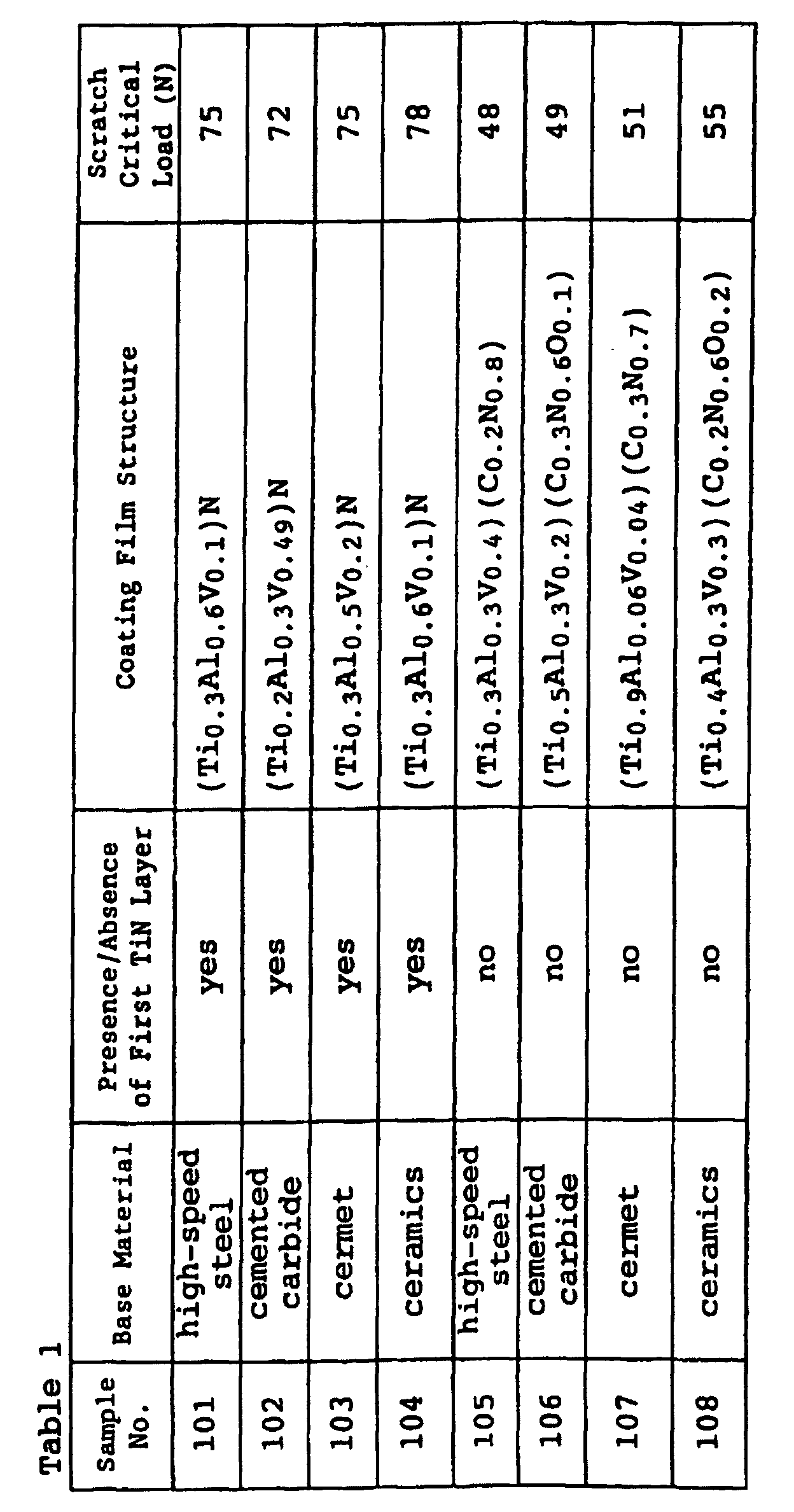
- Referring to Table 1, "high-speed steel" indicates base materials of grade JIS SKH51 high-speed steel. "Cemented carbide" indicates base materials of grade JIS P30 cemented carbide. "Cermet" indicates base materials of titanium carbo-nitride cermet. "Ceramics" indicates base materials of TiC-Al2O3 ceramics. Further, "scratch critical load" indicates loads applied to the diamond indenter in separation of the wear-resistant coating films. It is understood from Table 1 that the wear-resistant coating films of samples Nos. 101 to 104 provided with TiN films are higher in adhesion than those of samples Nos. 105 to 108 provided with no TiN films.
- While the coating film preparing apparatus shown in Figs. 1 and 2 has two
metal evaporation sources metal evaporation sources metal evaporation sources metal evaporation sources metal evaporation sources 8 to 11 were connected to dc power sources. Aheater 7 was arranged on a position different from that shown in Figs. 1 and 2. The remaining points of the coating film preparing apparatus shown in Figs. 3 and 4 are identical to those of the apparatus shown in Figs. 1 and 2. - In this apparatus, a plurality of samples having different thicknesses, compositions and layer structures were formed on base materials in a similar procedure to that in Example 1, as shown in Tables 2 and 3. In case of forming first TiN layers on the base materials, films A and B having the thicknesses and compositions shown in Table 2 were successively and alternately formed on the first TiN layers to attain the overall thicknesses shown in Table 3. A scratch test was made on these samples with a diamond indenter, to evaluate adhesion strength of wear-resistant coating films. Further, Knoop hardness values (measurement load: 20 g) of the wear-resistant coating films were measured. Tables 2 and 3 show the results.

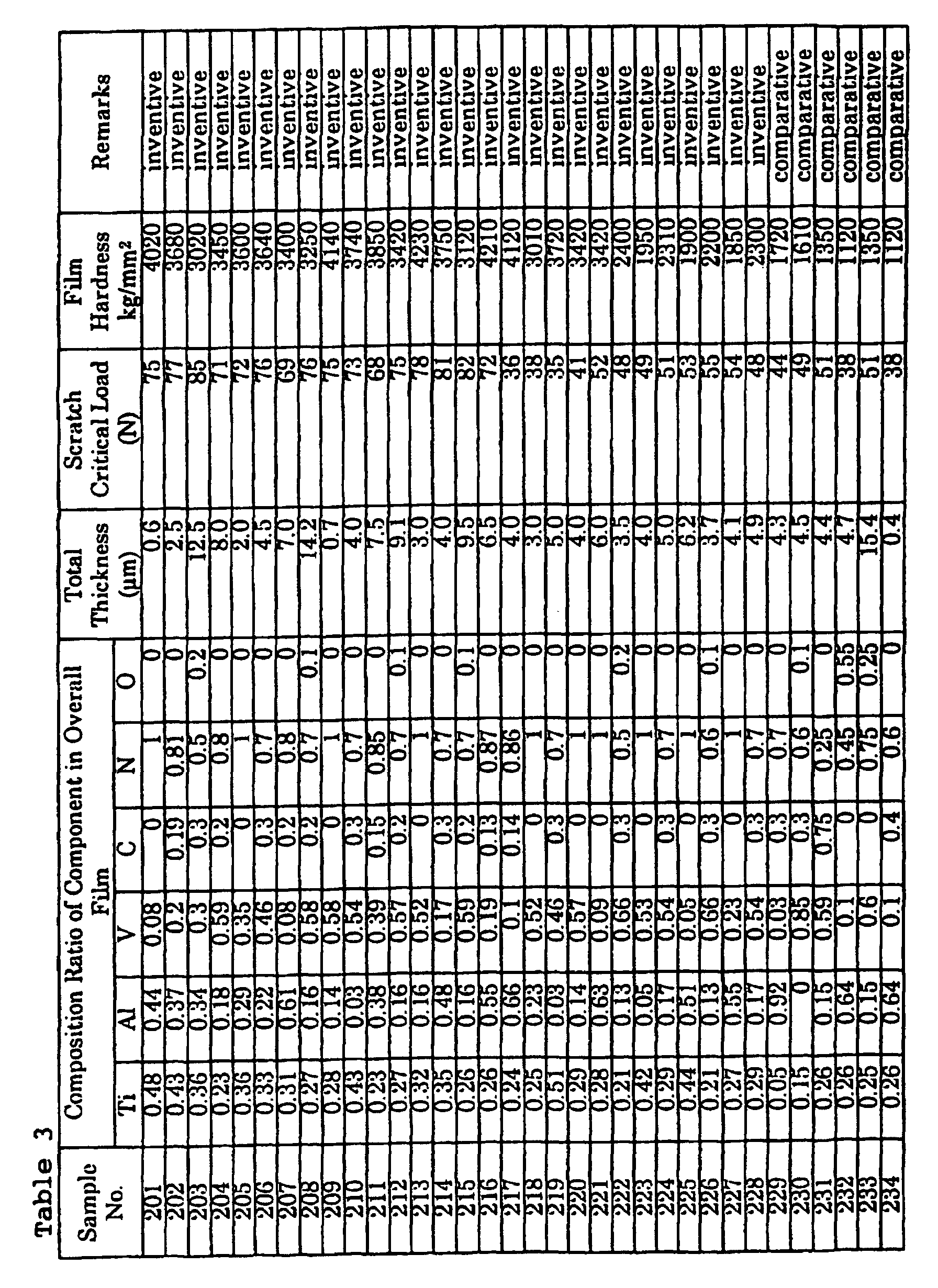
- Referring to Table 2, "arc IP" indicates wear-resistant coating films prepared by cathodic ion plating. "Sputtering" indicates wear-resistant coating films prepared by sputtering. "Film composition" indicates atomic ratios of components contained in the films. Referring to Table 3, "composition ratio of component in overall film" indicates the atomic ratios of the respective components in the overall films.
- It is understood from Tables 2 and 3 that the inventive samples Nos. 201 to 216 provided with TiN layers exhibited larger scratch critical loads and higher adhesion as compared with the samples Nos. 217 to 228 provided with no TiN films. The samples Nos. 229 to 234 exhibited low scratch critical loads since the atomic ratios of the components forming the films or the overall thicknesses were out of the inventive ranges.
- The coating films of the samples Nos. 201, 202, 204 to 207, 209 to 214, 216, 217 and 219 to 221 exhibited particularly high hardness. This is conceivably because the so-called strain conformity took place due to reduction of the film thicknesses.
- Thus, it is understood that the wear-resistant coating films of the inventive samples are higher in adhesion and hardness than those of the comparative samples.
- End mills having coating films of various compositions were prepared in the procedure of Example 1. The base materials of the end mills were prepared by JIS P30 cemented carbide. The structures of these coating films were examined by -2 X-ray diffraction. Further, these end mills were subjected to a cutting performance test under the following cutting conditions:
- End Mill: 6 mm, two edges, JIS P30 cemented carbide
- Workpiece: titanium alloy (Ti-6Al-4V)
- Cutting Method: lateral down cutting
- Cutting Speed: 80 m/min.
- Feed Rate: 0.03 mm/edge
- Feed: Rd 1
mm x Ad 7 mm - Condition: dry air blow
- Evaluation: outer peripheral flank wear width at a cut length of 20 m
-
- Tables 4 and 5 show the results. Referring to Table 4, "maximum intensity plane in X-ray diffraction" indicates planes relatively exhibiting maximum intensity among diffraction lines derived from the wear-resistant coating films examined by -2 X-ray diffraction.
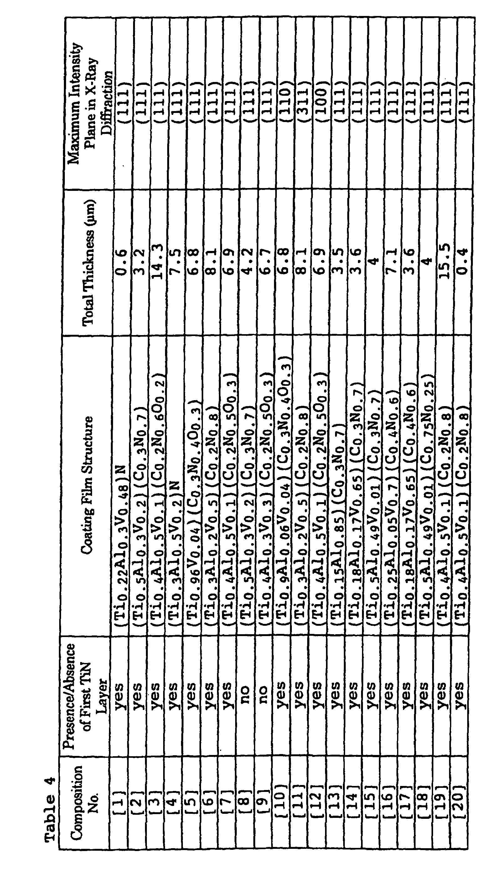
Sample No. Base Material Composition No. Flank Wear Width (mm) Remarks 301 cemented carbide [1] 0.19 inventive 302 [2] 0.13 inventive 303 [3) 0.2 inventive 304 [4] 0.14 inventive 305 [5] 0.18 inventive 306 [6] 0.16 inventive 307 [7] 0.18 inventive 308 [8] 0.35 inventive 309 [9] 0.29 inventive 310 [10] 0.29 inventive 311 [11] 0.27 inventive 312 [12] 0.25 inventive 313 [13] 0.68 comparative 314 [14] 0.65 comparative 315 [15] 0.75 comparative 316 [16] 0.72 comparative 317 [17] 0.65 comparative 318 [18] 0.75 comparative 319 [19] 0.85 comparative 320 [20] 0.54 comparative - It is understood from Tables 4 and 5 that the inventive samples Nos. 308 and 309 provided with no TiN films serving as adhesion layers and the inventive samples Nos. 310 to 312 not oriented along (111) planes exhibited somewhat large flank wear widths since the films were readily separated or had low hardness. It is also understood that the samples Nos. 313 to 318 having compositions of components which were out of the inventive ranges and the samples Nos. 319 and 320 having film thicknesses which were out of the inventive range exhibited extremely large flank wear widths. Further, worn states of inserts were observed in detail in all samples. Consequently, it has been recognized that small chipping was accumulated on the forward end portions of the inserts to result in large flank wear widths in the samples Nos. 313 to 320 due to growth and falling of built-up edges after cutting readily deposited titanium alloys.
- Wear-resistant coating films of various compositions were formed in a procedure similar to Example 2, to prepare drills. The base materials for the drills were prepared from JIS SKH51 high-speed steel. These drills were subjected to a cutting performance test in perforation under the following cutting conditions:
- Drill: 10 mm, SKH51 high-speed steel
- Workpiece: SS41
- Cutting Speed: 30 m/min.
- Feed Rate: 0.15 mm/rev.
- Cut Length: 30 mm (through hole)
- Cutting Oil: dry type
- Determination of Life: number of worked holes whose diameters exceeded a reference value (10 ± 0.05 mm)
-
- Tables 6 to 8 show the compositions, thicknesses, structures and test results of the wear-resistant coating films.


Sample No. Base Material Method Composition No. Number of Workable Holes (Holes) Remarks 401 high-speed steel sputtering [21] 680 inventive 402 [22] 654 inventive 403 [23] 691 inventive 404 [24] 668 inventive 405 [25] 531 inventive 406 [26] 702 inventive 407 [27] 850 inventive 408 [28] 765 inventive 409 [29] 454 inventive 410 [30] 431 inventive 411 [31] 424 inventive 412 [32] 412 inventive 413 [33] 423 inventive 414 [34] 454 inventive 415 [35] 350 inventive 416 [36] 350 inventive 417 [37] 415 inventive 418 [38] 398 inventive 419 [39] 426 inventive 420 [40] 447 inventive 421 [41] 398 inventive 422 [42] 426 inventive 423 [43] 113 comparative 424 [44] 89 comparative 425 [45] 106 comparative 426 [46] 98 comparative 427 [47] 108 comparative 428 [48] 102 comparative 429 [49] 85 comparative 430 [50] 75 comparative 431 [51] 95 comparative 432 [52] 97 comparative - In X-ray diffraction, a diffraction line from a (111) plane exhibited a high peak (maximum intensity) in each sample of the compositions Nos. [21] to [29]. It is understood from Tables 6 to 8 that the samples Nos. 401 to 408 provided with the films A and B in thicknesses of 0.5 nm to 50 nm had particularly large numbers of worked holes. This is conceivably because the films A and B were completely brought into face-centered cubic structures due to the so-called strain conformity. On the other hand, the number of worked holes was slightly small in the sample No. 409 provided with no TiN layer serving as an adhesion layer, although the film thickness was in the preferable range. In the samples Nos. 410 and 411, the numbers of worked holes were small conceivably because these samples were provided with no TiN films. Further, the numbers of worked holes were small conceivably because the thicknesses of the films A and B were out of the range of 0.5 to 50 nm in the samples Nos. 412 to 414, and conceivably because the thicknesses of the films A or B were out of the range of 0.5 to 500 nm in the samples Nos. 415 and 416. In addition, the numbers of worked holes were small conceivably because the films included structures other than fcc structures in the samples Nos. 417 and 418, and conceivably because the films were not oriented along (111) planes in the samples Nos. 419 to 422. On the other hand, the numbers of worked holes were extremely small in the samples Nos. 423 to 432 conceivably because the compositions or thicknesses of the films were out of the inventive ranges.
- Wear-resistant coating films having the compositions Nos. [21] to [52] in Example 4 were formed by arc ion plating in a procedure similar to Example 2, to manufacture milling tips. The base materials of the tips were prepared from titanium carbo-nitride cermet. These tips were subjected to a cutting performance test in milling under the following cutting conditions:
- Tip: SDKN42, JIS P10 titanium carbo-nitride cermet
- Workpiece: SS41
- Cutting Speed: 150 m/min.
- Feed Rate: 0.15 mm/edge
- Depth of Cut: 7.0 mm
- Cutting Oil: dry type
- Determination of Life: flank wear width at a cut length of 30 m
-
- Table 9 shows the results of the test.
Sample No. Base Material Method Composition No. Flank Wear Width (mm) Remarks 501 cermet arc IP [21] 0.11 inventive 502 [22] 0.12 inventive 503 [23] 0.10 inventive 504 [24] 0.12 inventive 505 [25] 0.10 inventive 506 [26] 0.13 inventive 507 [27] 0.12 inventive 508 [28] 0.09 inventive 509 [29] 0.18 inventive 510 [30] 0.21 inventive 511 [31] 0.20 inventive 512 [32] 0.19 inventive 513 [33] 0.16 inventive 514 [34] 0.17 inventive 515 [35] 0.18 inventive 516 [36] 0.21 inventive 517 [37] 0.22 inventive 518 [38] 0.19 inventive 519 [39] 0.23 inventive 520 [40] 0.25 inventive 521 [41] 0.25 inventive 522 [42] 0.23 inventive 523 [43] 0.44 comparative 524 [44] 0.42 comparative 525 [45] 0.48 comparative 526 [46] 0.57 comparative 527 [47] 0.65 comparative 528 [48] 0.80 comparative 529 [49] 0.95 comparative 530 [50] 0.76 comparative 531 [51] 0.88 comparative 532 [52] 0.64 comparative - It has been confirmed from Table 9 that the milling tips of the inventive samples Nos. 501 to 522 were smaller in flank wear width and longer in life as compared with those of the samples Nos. 523 to 530 which were out of the inventive ranges and conventional samples Nos. 531 and 532.
- Wear-resistant coating films having the compositions Nos. [21] to [52] in Example 4 were formed by sputtering in a procedure similar to Example 2, to prepare turning tips. The base materials of the tips were prepared from Al2O3-TiC ceramics. These tips were subjected to a cutting performance test in continuous turning under the following conditions:
- Tip: CNMN 433, JIS K01 Al2O3-TiC ceramics
- Workpiece: FCD45
- Cutting Speed: 300, 230 and 180 m/min.
- Feed Rate: 0.1 mm/rev.
- Depth of Cut: 0.3 mm
- Cutting Oil: dry type
- Determination of Life: flank wear width at a cut length of 50 m
-
- Table 10 shows the results of the test.
Sample No. Base Material Method Composition No. Flank Wear Width (mm) Remarks 601 ceramic sputtering [21] 0.09 inventive 602 [22] 0.08 inventive 603 [23] 0.07 inventive 604 [24] 0.06 inventive 605 [25] 0.08 inventive 606 [26] 0.09 inventive 607 [27] 0.08 inventive 608 [28] 0.09 inventive 609 [29] 0.12 inventive 610 [30] 0.13 inventive 611 [31] 0.14 inventive 612 [32] 0.15 inventive 613 [33] 0.16 inventive 614 [34] 0.14 inventive 615 [35] 0.15 inventive 616 [36] 0.16 inventive 617 [37] 0.15 inventive 618 [38] 0.14 inventive 619 [39] 0.18 inventive 620 [40] 0.17 inventive 621 [41] 0.17 inventive 622 [42] 0.18 inventive 623 [43] 0.51 comparative 624 [44] 0.62 comparative 625 [45] 0.38 comparative 626 [46] 0.76 comparative 627 [47] 0.88 comparative 628 [48] 0.64 comparative 629 [49] 0.85 comparative 630 [50] 0.74 comparative 631 [51] 0.77 comparative 632 [52] 0.76 comparative - From Table 10, it has been confirmed that the tips of the inventive samples Nos. 601 to 622 were smaller in flank wear width and longer in life as compared with the tips of the samples Nos. 623 to 630 which were out of the inventive ranges and conventional samples Nos. 631 and 632.
- Drills having wear-resistant coating films of various compositions were prepared by arc ion plating in a procedure similar to Example 2. The base materials of the drills were prepared from JIS K10 cemented carbide. For the purpose of comparison, drills having base materials of the same materials and shapes as those of the inventive samples, which were coated with wear-resistant coating films containing no vanadium, were prepared. Further, drills having such wear-resistant coating films coated with molybdenum disulfide were prepared. The coatings of molybdenum disulfide were formed by sputtering. These drills were subjected to a cutting performance test in perforation under the following cutting conditions:
- Tool: 10 mm, twist drill, JIS K10 cemented carbide
- Workpiece: S50C
- Cutting Speed: 70 m/min.
- Feed Rate: 0.3 mm/rev.
- Depth of Hole: 32 mm (blind hole)
- Cutting Oil: dry type
- Determination of Life: number of workable holes
- Other Evaluation: change of inner diameter of worked hole and number of workable holes
-
- Table 11 shows the results of the test.

- It has been confirmed from Table 11 that the drills of the inventive samples Nos. 701 to 705 were excellent not only in number of workable holes but in accuracy of the inner diameters of the worked holes. It has also been recognized that the sample No. 705 provided with no TiN layer serving as an adhesion layer was slightly smaller in number of workable holes and inferior in accuracy as compared with the remaining inventive samples Nos. 701 to 704. On the other hand, each of the drills of comparative samples Nos. 706 and 707 was broken before working 500 holes. Therefore, it was impossible to measure accuracy of the inner diameters of the holes upon working of 500 holes. Further, each of the drills of the comparative samples Nos. 708 and 709 exhibited high accuracy of inner diameters up to working of 100 holes. When the number of worked holes exceeded 100, however, swarfs so abnormally extended that continuation of the test was dangerous, and hence the test was stopped. After the test, it has been proved that the drill lost the molybdenum disulfide coating serving as a lubricating film due to its wear to lose the lubricative effect, by examination of the surface state of the drill.
- Wear-resistant coating films of various compositions were formed on base materials consisting of die steel in a procedure similar to Example 1. Adhesion strength values of the wear-resistant coating films were measured by a scratch test with a diamond indenter. Table 12 shows the results.

- It has been recognized from Table 12 that the inventive samples Nos. 801 to 803 provided with TiN layers serving as adhesion layers were higher in adhesion strength as compared with the sample No. 804 provided with no TiN layer.
- Wear-resistant coating films having various compositions were formed on base materials consisting of die steel in a procedure similar to Example 2. Adhesion strength values of the wear-resistant coating films were measured by a scratch test with a diamond indenter. Further, Knoop hardness values (measurement load: 25 g) of the wear-resistant coating films were measured. Table 13 shows the results.

- It is understood from Table 13 that the samples Nos. 901 to 905 provided with films A and B in thicknesses which were in the range of 0.5 to 50 nm exhibited particularly high hardness. This is conceivably because the so-called strain conformity took place in the films A and B. The samples Nos. 906 to 908 provided with films A and B in thicknesses which were out of the range of 0.5 to 500 nm were slightly lower in hardness as compared with the samples Nos. 901 to 905. Among the samples Nos. 901 to 905 provided with the films A and B in thicknesses which were in the range of 0.5 to 50 nm, the samples Nos. 901 to 904 provided with TiN layers serving as adhesion layers were higher in adhesion as compared with the sample No. 905 provided with no TiN layer.
- Wear-resistant coating films having the compositions Nos. [1] to [20] in Table 4 were formed on base materials consisting of cemented carbide by arc ion plating in a procedure similar to Example 1, to prepare punches for cold forging. These punches were subjected to a life evaluation test in cold forging under the following conditions:
- Punch Shape: forward end 15 mm, JIS V40 cemented carbide
- Workpiece: rod cut body of Cr-V steel
- Part Name: socket wrench head
- Forging Speed: 50 cycles/min.
- Used Machine: press of 200 tons
- Lubrication of Workpiece: no
- Die: shrinkage-fitted in JIS V40 cemented carbide + steel case
- Evaluation: workable quantity up to seizure
-
- Table 14 shows the results.
Sample No. Base material Composition No. Workable Quantity (thou.) Remarks 1001 cemented carbide [1] 120 inventive 1002 [2] 115 inventive 1003 [3] 130 inventive 1004 [4] 115 inventive 1005 [5] 132 inventive 1006 [6] 125 inventive 1007 [7] 126 inventive 1008 [8] 95 inventive 1009 [9] 97 inventive 1010 [10] 89 inventive 1011 [11] 93 inventive 1012 [12] 91 inventive 1013 [13] 15 comparative 1014 [14] 23 comparative 1015 [15] 18 comparative 1016 [16] 17 comparative 1017 [17] 5 comparative 1018 [18] 8 comparative 1019 [19] 27 comparative 1020 [20] 3 comparative - As understood from Table 14, the samples Nos. 1001 to 1007 provided with TiN layers serving as adhesion layers and having compositions and thicknesses which were in the inventive ranges and maximum intensity planes of X-ray diffraction in (111) planes exhibited particularly excellent results. The workable quantities of the samples Nos. 1008 and 1009 provided with no TiN films and the samples Nos. 1010 to 1013 having films not oriented on (111) planes were slightly reduced as compared with the samples Nos. 1001 to 1007. On the other hand, the workable quantities were remarkably small in the samples Nos. 1013 to 1018 and Nos. 1019 and 1021 having film compositions and film thicknesses which were out of the inventive ranges respectively.
- Worn states of the punches of the samples Nos. 1017 to 1020 were observed in detail, to find that the forward end portions of these punches were chipped due to growth and falling of deposits since forging was performed with no lubricants.
- Wear-resistant coating films having the compositions Nos. [21] to [52] in Example 4 were formed on base materials consisting of hot die steel by sputtering in a procedure similar to Example 2, to prepare punches for warm forging. These punches were subjected to a life evaluation in warm forging under the following conditions:
- Punch Shape: forward end 80 mm, SKD61 hot die steel
- Workpiece: S45C
- Part Name: outer race of isokinetic ball joint
- Temperature in Forging: 800°C
- Forging Speed: 50 cycles/min.
- Used Machine: press of 1000 tons
- Lubrication of Workpiece: with boric acid lubricant
- Die: SKD61 hot die steel
- Evaluation: workable quantity up to seizure
-
- Table 15 shows the results.
Sample No. Base Material Method Composition No. Workable Quantity (thou.) Remark 1101 hot die steel SKD61 sputtering [21] 21 inventive 1102 [22] 20 inventive 1103 [23] 19 inventive 1104 [24] 20 inventive 1105 [25] 19 inventive 1106 [26] 20 inventive 1107 [27] 21 inventive 1108 [28] 21 inventive 1109 [29] 13 inventive 1110 [30] 12 inventive 1111 [31] 14 inventive 1112 [32] 13 inventive 1113 [33] 15 inventive 1114 [34] 14 inventive 1115 [35] 13 inventive 1116 [36] 12 inventive 1117 [37] 13 inventive 1118 [38] 14 inventive 1119 [39] 16 inventive 1120 [40] 14 inventive 1121 [41] 12 inventive 1122 [42] 13 inventive 1123 [43] 8 comparative 1124 [44] 6 comparative 1125 [45] 7 comparative 1126 [46] 6 comparative 1127 [47] 8 comparative 1128 [48] 7 comparative 1129 [49] 9 comparative 1130 [50] 4 comparative 1131 [51] 5 comparative 1132 [52] 7 comparative - It has been recognized from Table 15 that the inventive samples Nos. 1101 to 1122 exhibited larger workable quantities as compared with samples Nos. 1123 to 1130 which were out of the inventive ranges and conventional samples Nos. 1131 and 1132.
- Worn states of the punches of the samples Nos. 1123 to 1132 were observed in detail, to find that the forward end portions of these punches were broken by growth and falling of deposits due to forging with boric acid lubricants having incomplete lubricating functions. This is conceivably the reason why the samples Nos. 1123 to 1132 had short lives.
- Wear-resistant coating films having the compositions Nos. [21] to [52] in Example 4 were formed on base materials consisting of hot die steel by arc ion plating in a procedure similar to Example 2, to prepare punches for hot forging. These punches were subjected to a life evaluation test in actual hot punching under the following conditions:
- Punch shape: forward end 40 mm, SKD 61 hot die steel
- Workpiece: SUJ2
- Part Name: outer race of ball bearing
- Temperature in Forging: 900°C
- Working Speed: 60 times/min.
- Used Machine: press of 200 tons
- Lubrication of Workpiece: with boric acid lubricant
- Die: SKD61 hot die steel
- Evaluation: workable quantity up to seizure
-
- Table 16 shows the results of the test.
Sample No. Base Material Method Composition No. Workable Quantity (thou.) Remarks 1201 hot die steel SKD61 arc IP [21] 8 inventive 1202 [22] 9 inventive 1203 [23] 8 inventive 1204 [24] 10 inventive 1205 [25] 9 inventive 1206 [26] 8 inventive 1207 [27] 9 inventive 1208 [28] 9 inventive 1209 [29] 7 inventive 1210 [30] 7 inventive 1211 [31] 6 inventive 1212 [32] 7 inventive 1213 [33] 5 inventive 1214 [34] 6 inventive 1215 [35] 6 inventive 1216 [36] 7 inventive 1217 [37] 5 inventive 1218 [38] 6 inventive 1219 [39] 6 inventive 1220 [40] 7 inventive 1221 [41] 6 inventive 1222 [42] 6 inventive 1223 [43] 3 comparative 1224 [44] 2 comparative 1225 [45] 3 comparative 1226 [46] 3 comparative 1227 [47] 2 comparative 1228 [48] 2 comparative 1229 [49] 3 comparative 1230 [50] 2 comparative 1231 [51] 3 comparative 1232 [52] 2 comparative - It has been recognized from Table 16 that the inventive samples Nos. 1201 to 1222 exhibited larger workable quantities than the samples Nos. 1223 to 1230 which were out of the inventive ranges and conventional samples Nos. 1231 and 1232.
- Wear-resistant coating films having the compositions Nos. [21] to [52] in Example 4 were formed on base materials consisting of high-speed steel by sputtering in a procedure similar to Example 2, to prepare molds. These molds were subjected to a life evaluation test in cold punching under the following conditions:
- Punch Shape: forward end 30 mm, SKH9 high-speed steel
- Workpiece: SS41 (thickness: 6 mm)
- Part Name: transformer container
- Working Speed: 120 times/min.
- Used Machine: NC press of 50 tons
- Lubrication of Workpiece: with press oil containing extreme pressure agent
- Die: SKH9 high-speed steel
- Evaluation: workable quantity up to seizure
-
- Table 17 shows the results of the test.
Sample No. Base Material Method Composition No. Workable Quantity (thou.) Remarks 1301 high-speed steel (SKH9) sputtering [21] 135.00 inventive 1302 [22] 140.00 inventive 1303 [23] 133.00 inventive 1304 [24] 129.00 inventive 1305 [25] 128.00 inventive 1306 [26] 132.00 inventive 1307 [27] 129.00 inventive 1308 [28] 127.00 inventive 1309 [29] 110.00 inventive 1310 [30] 106.00 inventive 1311 [31] 105.00 inventive 1312 [32] 104.00 inventive 1313 [33] 107.00 inventive 1314 [34] 112.00 inventive 1315 [35] 113.00 inventive 1316 [36] 115.00 inventive 1317 [37] 112.00 inventive 1318 [38] 113.00 inventive 1319 [39] 104.00 inventive 1320 [40] 101.00 inventive 1321 [41] 102.00 inventive 1322 [42] 106.00 inventive 1323 [43] 51.00 comparative 1324 [44] 35.00 comparative 1325 [45] 32.00 comparative 1326 [46] 28.00 comparative 1327 [47] 26.00 comparative 1328 [48] 24.00 comparative 1329 [49] 34.00 comparative 1330 [50] 19.00 comparative 1331 [51] 15.00 comparative 1332 [52] 17.00 comparative - It has been recognized from Table 17 that the inventive samples Nos. 1301 to 1322 exhibited larger workable quantities than the samples Nos. 1323 to 1330 which were out of the inventive ranges and conventional samples Nos. 1331 and 1332.
- A method of forming a coating film is now illustrated with reference to cathodic arc ion plating.
- As shown in Figs. 1 and 2, a
prescribed base material 2 cleaned with a cleaning solution such as an organic solvent is set on thebase material support 3 which is rotatable along arrow R. Evaporation sources consisting of alloys containing Ti, Al and V in prescribed ratios or the respective single metal components are set on the twometal evaporation sources - The interior of the reaction vessel 1 is evacuated with a vacuum evacuation apparatus (not shown) so that the internal pressure is not more than 1 x 10⁻³ Pa, and argon gas is fed from the material gas supply nozzle 4 and the
base material 2 is heated with thebase material heater 7. Thebase material 2 consisting of cemented carbide is preferably heated to a temperature of 550 to 600°C. After the temperature of thebase material 2 is increased to the prescribed level, the flow rate of argon gas is so adjusted that the internal pressure of the reaction vessel 1 is 2.7 Pa (20 mTorr), and power of -1000 V is applied to thebase material support 3 and thebase material 2 from thedc power source 5 to generate argon plasma in the reaction vessel 1, for plasma-cleaning the surface of thebase material 2. Due to the operation, soil and an oxide film are removed from the surface of thebase material 2. - Then, argon gas is discharged from the reaction vessel 1, nitrogen gas is introduced from the material gas supply nozzle 4 so that the internal pressure of the reaction vessel 1 is 4.0 Pa (30 mTorr), and the voltage of the
dc power source 5 is reduced to -200 V. Power of -30 V and 100 A is supplied from the cathodicarc power sources metal evaporation sources evaporation sources evaporation sources base material 2. Thus, a (Ti,Al,V)N film or single metal nitride films such as a TiN film and a VN film, for example, are obtained. - In order to obtain a carbo-nitride film, hydrocarbon gas such as methane gas may be fed from the material gas supply nozzle 4 into the reaction vessel 1.
- For preparing each of inventive samples, power was supplied to an evaporation source consisting of only metal titanium, to form a titanium nitride (TiN) film in a prescribed thickness as a film adjacent to the surface of the
base material 2. Thereafter power was supplied to an evaporation source of a Ti-V or Ti-V-Al alloy having a prescribed alloy composition to react the alloy with nitrogen gas or mixed gas of nitrogen gas and hydrocarbon gas. Thus, (Ti,V)N, (Ti,Al,V)(C,N), (Ti,Al,V)N and (Ti,V)(C,N) films of inventive samples 1 to 6 were formed in compositions shown in Table 18. - After formation of each coating film, supply of the cathodic
arc power sources dc power source 5 was stopped, and thebase material heater 7 was turned off. Thereafter thebase material 2 was cooled 2 to a temperature of not more than 100°C, and taken out from the reaction vessel 1. - The
base material 2 was prepared from grade JIS P30 cemented carbide in a tip shape of JIS SDKN42. For the purpose of comparison, titanium nitride films of comparative samples Nos. 2 and 4 and titanium aluminum nitride films of comparative samples Nos. 1, 3 and 5 were prepared in a method similar to the above. - The surfaces of the coating films of the inventive samples Nos. 1 to 3 were oxidized in the atmosphere at the temperature of 600°C for 30 minutes while those of the inventive samples Nos. 4 to 6 were oxidized in an atmosphere containing vapor at the temperature of 400°C for 30 minutes.
- Wear resistance and deposition resistance in a cutting test were evaluated under the following cutting test conditions:
- Cutting Method: face milling
- Workpiece: JIS SKD61 hot die steel
- Cutting Speed: 50 m/min.
- Feed Rate: 0.18 mm/edge
- Depth of Cut: 2.0 mm
- Cutting Oil: dry type
- Determination of Life: flank wear width at a cut length of 10 m (or cut length up to chipping)
-
- Table 18 shows the results of the cutting test.

- As shown in Table 18, it was possible to suppress chipping of inserts in the coated cutting tools of the inventive samples, and it has been confirmed that the lives of these samples were longer than those of the cutting tools of the comparative samples coated with conventional coating films.
- Although the present invention has been described and illustrated in detail, it is clearly understood that the same is by way of illustration and example only and is not to be taken by way of limitation, scope of the present invention being limited only by the terms of the appended claims.
Claims (23)
- A coated tool comprising a base material and
a wear-resistant coating film formed on said base material, wherein:
when the composition of said wear-resistant coating film is expressed as (Tix,Aly,Vz)(Cu,Nv,Ow), where x, y, z, u, v and w represent the atomic ratios of Ti, Al, V, C, N and O receptively, x + y + z = 1, u + v + w = 1, 0.2 < x < 1, 0 ≤ y < 0.8, 0.02 ≤ z < 0.6, 0 ≤ u < 0.7, 0.3 < v ≤ 1, and
0 ≤ w < 0.5;
the thickness of said wear-resistant coating film is at least 0.5 µm and not more than 15 µm;
the outermost surface of said wear-resistant coating film is coated with a low melting point oxide containing vanadium oxide, said low melting point oxide having a melting point of not more than 1000°C and being formed during manufacture of said coated tool;
said wear-resistant coating film includes a plurality of stacked first films; and
when the composition of each of said first films is expressed as (Tia,Alb,Vc)(Cd,Ne,Of), where a, b, c, d, e and f represent the atomic ratios of Ti, Al, V, C, N and O respectively, a + b + c = 1, d + e + f = 1, 0.2 < a ≤ 1, 0 ≤ b < 0.8, 0 ≤ c < 0.6, 0 ≤ d < 0.7, 0.3 < e ≤ 1, and 0 ≤ f < 0.5. - A coated tool as claimed in claim 1,
wherein the thickness of each of said first films is at least 0.5 nm and not more than 500 nm. - A coated tool as claimed in claim 2, wherein the thickness of each of said first films is at least 0.5 nm and not more than 50 nm.
- A coated tool as claimed in claim 2, wherein the composition or thickness of each of said first films are different from each other.
- A coated tool as claimed in claim 1, wherein said wear-resistant coating film includes a plurality of stacked said first films and a second film, and wherein said second film contains at least one component selected from vanadium nitride, vanadium carbide, vanadium carbo-nitride, vanadium carbo-oxide, vanadium oxo-nitride and vanadium carbo-oxo-nitride.
- A coated tool as claimed in claim 5, wherein the thickness of each of said first and second films is at least 0.5 nm and not more than 500 nm.
- A coated tool as claimed in claim 6, wherein the thickness of each of said first and second films is at least 0.5 nm and not more than 50 nm.
- A coated tool as claimed in claim 5, wherein said first and second films are alternately stacked with each other.
- A coated tool as claimed in claim 1, wherein said wear-resistant coating film includes a plurality of stacked said first films and a third film, said third film containing at least one component selected from aluminium nitride and aluminium carbo-nitride, and wherein the thickness of said third film is at least 0.5 nm and not more than 50 nm.
- A coated tool as claimed in claim 9, wherein said first and third films are alternately stacked with each other.
- A coated tool as claimed in claim 1, wherein said wear-resistant coating film includes an adhesion layer consisting of TiN, and said adhesion layer is in contact with said base material.
- A coated tool as claimed in claim 1, wherein said base material contains at least one component selected from ceramics, cemented carbide, cermet, high-speed steel, die steel, prehardened steel and precipitation-hardened stainless steel.
- A coated tool as claimed in claim 1, wherein said wear-resistant coating film has a face-centered cubic structure, and a diffraction line from a (111) plane relatively exhibits the maximum intensity among those derived from said wear-resistant coating film when its crystal structure is examined by -2 X-ray diffraction.
- A coated tool as claimed in claim 3, wherein a diffraction pattern is formed only by diffraction lines derived from a single type face-centered cubic structure and a diffraction line from a (111) plane relatively exhibits the maximum intensity among those derived from said wear-resistant coating film having a face-centered cubic structure when its crystal structure is examined by -2 X-ray diffraction.
- A coated tool as claimed in claim 1, which is a coated cutting tool.
- A coated tool as claimed in claim 1, which is a coated mold.
- A coated cutting tool as claimed in claim 1,
wherein:the base material consists of a cemented carbide; andthe wear-resistant coating layer includes a titanium nitride film formed to be in contact with the surface of said base material and either (i) a composite nitride film formed on said titanium nitride film and containing titanium, vanadium, nitrogen and unavoidable impurities, or (ii) a composite carbo-nitride film formed on said titanium nitride film and containing titanium, vanadium, carbon, nitrogen and unavoidable impurities. - A coated cutting tool as claimed in claim 17, wherein said composite nitride film or composite carbo-nitride film further contains aluminium.
- A coated cutting tool as claimed in claim 17 or claim 18, wherein said wear-resistant coating film is formed on any one portion of a flank, a rake face, and an edge part corresponding to the boundary between said flank and said rake face.
- A coated cutting tool as claimed in claim 17, wherein the atomic ratio (vanadium) / {(titanium) + (vanadium)} in said composite nitride film is at least 0.02 and not more than 0.6.
- A coated cutting tool as claimed in claim 18, wherein the atomic ratio (vanadium) / (titanium) + (aluminium) + (vanadium)} in said composite nitride film is at least 0.02 and not more than 0.6.
- A method of manufacturing a coated cutting tool as defined in claim 17, the method comprising the steps of:forming said composite nitride film or composite carbo-nitride film on said titanium nitride film by (i) PVD with an evaporation source containing titanium and vanadium or an alloy of titanium and vanadium, and a reaction gas containing at least nitrogen, or (ii) PVD with an evaporation source containing titanium and vanadium or an alloy of titanium and vanadium, and a reaction gas containing at least nitrogen and a hydrocarbon; andoxidizing the surface of said composite nitride film or composite carbo-nitride film by a heat treatment in an atmosphere containing oxygen or vapour at a temperature of at least 400°C to form said low melting point oxide on the outermost surface of said composite nitride film or composite carbo-nitride film, wherein said low melting point oxide is formed during manufacture of said coated tool.
- A method as claimed in claim 22, wherein the evaporation source contains titanium, aluminium and vanadium or an alloy of a combination of at least two of titanium, aluminium and vanadium.
Applications Claiming Priority (6)
| Application Number | Priority Date | Filing Date | Title |
|---|---|---|---|
| JP32406796A JP3250966B2 (en) | 1996-12-04 | 1996-12-04 | Coated cutting tool and manufacturing method thereof |
| JP32406796 | 1996-12-04 | ||
| JP324067/96 | 1996-12-04 | ||
| JP3656797 | 1997-02-20 | ||
| JP03656797A JP4528373B2 (en) | 1997-02-20 | 1997-02-20 | Coated tool and manufacturing method thereof |
| JP36567/97 | 1997-02-20 |
Publications (3)
| Publication Number | Publication Date |
|---|---|
| EP0846784A2 EP0846784A2 (en) | 1998-06-10 |
| EP0846784A3 EP0846784A3 (en) | 2000-12-20 |
| EP0846784B1 true EP0846784B1 (en) | 2004-09-08 |
Family
ID=26375638
Family Applications (1)
| Application Number | Title | Priority Date | Filing Date |
|---|---|---|---|
| EP19970309334 Expired - Lifetime EP0846784B1 (en) | 1996-12-04 | 1997-11-20 | Coated tool and method of manufacturing the same |
Country Status (3)
| Country | Link |
|---|---|
| US (1) | US5981049A (en) |
| EP (1) | EP0846784B1 (en) |
| DE (1) | DE69730576T2 (en) |
Cited By (1)
| Publication number | Priority date | Publication date | Assignee | Title |
|---|---|---|---|---|
| RU2640691C1 (en) * | 2016-12-20 | 2018-01-11 | федеральное государственное бюджетное образовательное учреждение высшего образования "Ульяновский государственный технический университет" | Method of producing multi-layer coating for cutting tool |
Families Citing this family (42)
| Publication number | Priority date | Publication date | Assignee | Title |
|---|---|---|---|---|
| US6613410B1 (en) * | 1999-09-23 | 2003-09-02 | National Label Company | Extended wrap label |
| WO1999040233A1 (en) * | 1998-02-04 | 1999-08-12 | Osg Corporation | Multilayer coated tool |
| JP2000005904A (en) * | 1998-06-18 | 2000-01-11 | Sumitomo Metal Mining Co Ltd | Surface-treated steel cutting tools |
| WO2000008234A1 (en) * | 1998-08-05 | 2000-02-17 | Alexei Anatolievich Vereschaka | Multilayer composite wear resistant coating |
| US6296928B1 (en) | 1998-10-27 | 2001-10-02 | Mmc Kobelco Tool Co., Ltd. | Hard coating coated member having excellent wear resistance |
| SE9903089D0 (en) * | 1999-09-01 | 1999-09-01 | Sandvik Ab | Coated grooving or parting insert |
| DE10002861A1 (en) * | 2000-01-24 | 2001-08-09 | Walter Ag | Cutting tool with carbonitride coating |
| TW512181B (en) * | 2000-02-03 | 2002-12-01 | Cosmos Vacuum Technology Corp | A process for covering a film on the surface of the micro cutting router by coating super micro atomized multi-elements |
| EP1132498B1 (en) * | 2000-03-09 | 2008-05-07 | Sulzer Metaplas GmbH | Hard layer coated parts |
| DE10011597A1 (en) * | 2000-03-10 | 2001-09-13 | Hauzer Techno Coating Europ B | Production of decorative hard layers comprises depositing a metal carbonitride and/or a metal carbonitride oxide on a substrate |
| RU2191220C2 (en) * | 2000-08-14 | 2002-10-20 | Уральский электрохимический комбинат | Wear-resistant coating |
| RU2194086C2 (en) * | 2000-10-11 | 2002-12-10 | Уральский электрохимический комбинат | Abrasion-resistant coat for parts manufactured from stainless steel |
| US20040008950A1 (en) * | 2001-03-20 | 2004-01-15 | Daiichi Kasei Co., Ltd. | Resin ferrule for use in optical fiber connector and molding die therefor |
| DE10233222B4 (en) * | 2001-07-23 | 2007-03-01 | Kabushiki Kaisha Kobe Seiko Sho (Kobe Steel, Ltd.), Kobe | Hard wear-resistant layer, method of forming same and use |
| DE60210399T2 (en) * | 2001-11-28 | 2006-08-24 | Metaplas Ionon Oberflächenveredelungstechnik GmbH | Parts coated with a hard coating |
| US6660133B2 (en) | 2002-03-14 | 2003-12-09 | Kennametal Inc. | Nanolayered coated cutting tool and method for making the same |
| EP2865784A1 (en) * | 2002-08-08 | 2015-04-29 | Kabushiki Kaisha Kobe Seiko Sho (Kobe Steel, Ltd.) | Process for producing alumina coating composed mainly of alpha-type crystal structure |
| SE526339C2 (en) * | 2002-09-04 | 2005-08-23 | Seco Tools Ab | Cut with durable refractory coating with composite structure |
| SE526338C2 (en) * | 2002-09-04 | 2005-08-23 | Seco Tools Ab | Cut with a hardened, hardened refractory coating |
| AT6792U1 (en) * | 2002-10-14 | 2004-04-26 | Plansee Tizit Ag | LOW FRICTION TOOL OR COMPONENT |
| US7211138B2 (en) * | 2003-02-07 | 2007-05-01 | Kabushiki Kaisha Kobe Seiko Sho (Kobe Steel, Ltd.) | Hard film, method of forming the same and target for hard film formation |
| SE527349C2 (en) * | 2003-04-24 | 2006-02-14 | Seco Tools Ab | Cutter with coating of layers of MTCVD-Ti (C, N) with controlled grain size and morphology and method of coating the cutter |
| SE527346C2 (en) * | 2003-04-24 | 2006-02-14 | Seco Tools Ab | Cutter with coating of layers of MTCVD-Ti (C, N) with controlled grain size and morphology and method of coating the cutter |
| JP2005271190A (en) * | 2003-12-05 | 2005-10-06 | Sumitomo Electric Hardmetal Corp | Surface coated cutting tool |
| JP5060714B2 (en) * | 2004-09-30 | 2012-10-31 | 株式会社神戸製鋼所 | Hard coating excellent in wear resistance and oxidation resistance, and target for forming the hard coating |
| GB2425780B (en) | 2005-04-27 | 2007-09-05 | Univ Sheffield Hallam | PVD coated substrate |
| IL182741A (en) | 2007-04-23 | 2012-03-29 | Iscar Ltd | Coatings |
| JP2009068047A (en) | 2007-09-11 | 2009-04-02 | Kobe Steel Ltd | Hard coating film, material coated with hard coating film and die for cold plastic working |
| BRPI1012814B1 (en) | 2009-05-22 | 2019-02-19 | Nippon Steel & Sumitomo Metal Corporation | METHOD FOR MACHINING STEEL FOR USE IN MACHINE STRUCTURES |
| US20110094876A1 (en) * | 2009-10-27 | 2011-04-28 | Yi-Hsiang Liang | Germanium-containing vacuum coating for noble-metal components |
| US8409734B2 (en) * | 2011-03-04 | 2013-04-02 | Kennametal Inc. | Coated substrates and methods of making same |
| US9238865B2 (en) | 2012-02-06 | 2016-01-19 | Asm Ip Holding B.V. | Multiple vapor sources for vapor deposition |
| JP2014122400A (en) | 2012-12-21 | 2014-07-03 | Kobe Steel Ltd | Hard film excellent in cohesion resistance to soft metal |
| JP6071100B1 (en) * | 2015-03-27 | 2017-02-01 | 株式会社タンガロイ | Coated cutting tool |
| WO2018008554A1 (en) | 2016-07-07 | 2018-01-11 | 三菱日立ツール株式会社 | Hard coating, hard coating-covered tool, and methods for producing both |
| US11821073B2 (en) * | 2018-10-26 | 2023-11-21 | Oerlikon Surface Solutions Ag, Pfäffikon | Vanadium aluminium nitride (VAlN) micro alloyed with Ti and/or Si |
| CN109722637B (en) * | 2018-12-24 | 2021-09-07 | 中国科学院宁波材料技术与工程研究所 | Lubricating coating and preparation method thereof |
| WO2020137325A1 (en) * | 2018-12-27 | 2020-07-02 | 日本特殊陶業株式会社 | Surface-coated cutting tool |
| US11788190B2 (en) | 2019-07-05 | 2023-10-17 | Asm Ip Holding B.V. | Liquid vaporizer |
| US11946136B2 (en) | 2019-09-20 | 2024-04-02 | Asm Ip Holding B.V. | Semiconductor processing device |
| CN117845165A (en) * | 2024-02-21 | 2024-04-09 | 天津职业技术师范大学(中国职业培训指导教师进修中心) | Ti-Al-V-C nanocomposite coating with high oxidation resistance and high wear resistance |
| CN121109947A (en) * | 2025-08-07 | 2025-12-12 | 惠州学院 | An AlTiMoVN multi-element self-lubricating coating, its preparation method, and its application. |
Family Cites Families (13)
| Publication number | Priority date | Publication date | Assignee | Title |
|---|---|---|---|---|
| DE2851584B2 (en) * | 1978-11-29 | 1980-09-04 | Fried. Krupp Gmbh, 4300 Essen | Composite body |
| SU959344A1 (en) * | 1979-07-02 | 1983-05-23 | Всесоюзный Научно-Исследовательский Инструментальный Институт | Cutting tool |
| US4447263A (en) * | 1981-12-22 | 1984-05-08 | Mitsubishi Kinzoku Kabushiki Kaisha | Blade member of cermet having surface reaction layer and process for producing same |
| JPS60248879A (en) * | 1984-05-23 | 1985-12-09 | Toshiba Tungaloy Co Ltd | Surface coated hard alloy and its production |
| JPS61294659A (en) * | 1985-06-20 | 1986-12-25 | Sony Corp | Sliding member |
| JPS6274076A (en) * | 1985-09-27 | 1987-04-04 | Sumitomo Electric Ind Ltd | Manufacturing method of multi-layer coated hard alloy |
| US4714660A (en) * | 1985-12-23 | 1987-12-22 | Fansteel Inc. | Hard coatings with multiphase microstructures |
| SE453369C (en) * | 1986-05-28 | 1989-10-16 | Vni Instrument Inst | Durable Coating for Cutting Tools and Procedure for Coating |
| US4842710A (en) * | 1987-03-23 | 1989-06-27 | Siemens Aktiengesellschaft | Method of making mixed nitride films with at least two metals |
| JPH03112822A (en) * | 1989-09-25 | 1991-05-14 | Toshiba Tungaloy Co Ltd | Mold for molding optical part |
| JP2917312B2 (en) * | 1989-09-29 | 1999-07-12 | 住友電気工業株式会社 | Surface-coated carbide members for cutting and wear-resistant tools |
| JP3045184B2 (en) * | 1990-12-21 | 2000-05-29 | エムエムシーコベルコツール株式会社 | Wear-resistant hard coating, method for forming the same, and wear-resistant hard coating-coated tool |
| EP0496053B1 (en) * | 1991-01-21 | 1995-07-26 | Balzers Aktiengesellschaft | Coated highly wear-resistant tool and physical coating method for highly wear-resistant tools |
-
1997
- 1997-11-20 EP EP19970309334 patent/EP0846784B1/en not_active Expired - Lifetime
- 1997-11-20 US US08/974,522 patent/US5981049A/en not_active Expired - Lifetime
- 1997-11-20 DE DE1997630576 patent/DE69730576T2/en not_active Expired - Lifetime
Cited By (1)
| Publication number | Priority date | Publication date | Assignee | Title |
|---|---|---|---|---|
| RU2640691C1 (en) * | 2016-12-20 | 2018-01-11 | федеральное государственное бюджетное образовательное учреждение высшего образования "Ульяновский государственный технический университет" | Method of producing multi-layer coating for cutting tool |
Also Published As
| Publication number | Publication date |
|---|---|
| EP0846784A3 (en) | 2000-12-20 |
| EP0846784A2 (en) | 1998-06-10 |
| DE69730576T2 (en) | 2005-02-03 |
| US5981049A (en) | 1999-11-09 |
| DE69730576D1 (en) | 2004-10-14 |
Similar Documents
| Publication | Publication Date | Title |
|---|---|---|
| US5981049A (en) | Coated tool and method of manufacturing the same | |
| JP4528373B2 (en) | Coated tool and manufacturing method thereof | |
| CN1470350B (en) | Coated tool | |
| JP6383333B2 (en) | Workpiece and processing method thereof | |
| US6586122B2 (en) | Multilayer-coated cutting tool | |
| CA1248046A (en) | Multilayer coating including disordered, wear resistant boron carbon external coating | |
| JP4018480B2 (en) | Coated hard tool | |
| JP4132931B2 (en) | Hard film coated tool and manufacturing method thereof | |
| EP0075316A1 (en) | Coating composition and method | |
| JP2008012669A (en) | Coated tool with increased service life | |
| US6858333B2 (en) | Tool with wear resistant low friction coating and method of making the same | |
| JPH07171706A (en) | Coating tool and cutting process | |
| JP2002146515A (en) | Hard film superior in slidableness and its coating tool | |
| EP3661685B1 (en) | Tap drill with enhanced performance | |
| JP3719709B2 (en) | Amorphous carbon coated tool and method for manufacturing the same | |
| KR101170396B1 (en) | Hard coating and its production method | |
| JP3950385B2 (en) | Surface coated cutting tool | |
| JP3718664B2 (en) | Amorphous carbon coated tool and method for manufacturing the same | |
| JP2004042149A (en) | Coated cutting tool | |
| JP2002038255A (en) | Abrasion resistant lubricating-film and coated member | |
| WO2022129644A1 (en) | Hard alcr-based multilayer coating system, coated article and method for manufacturing the same | |
| JP4350822B2 (en) | Hard film and hard film coated member with excellent wear resistance | |
| Revuru et al. | Performance of coated cutting tools in machining: A review | |
| JP4217027B2 (en) | Covering member | |
| US6338879B1 (en) | Solid lubricant film for coated cutting tool and method for manufacturing same |
Legal Events
| Date | Code | Title | Description |
|---|---|---|---|
| PUAI | Public reference made under article 153(3) epc to a published international application that has entered the european phase |
Free format text: ORIGINAL CODE: 0009012 |
|
| AK | Designated contracting states |
Kind code of ref document: A2 Designated state(s): DE ES FR GB IT |
|
| AX | Request for extension of the european patent |
Free format text: AL;LT;LV;MK;RO;SI |
|
| PUAL | Search report despatched |
Free format text: ORIGINAL CODE: 0009013 |
|
| AK | Designated contracting states |
Kind code of ref document: A3 Designated state(s): AT BE CH DE DK ES FI FR GB GR IE IT LI LU MC NL PT SE |
|
| AX | Request for extension of the european patent |
Free format text: AL;LT;LV;MK;RO;SI |
|
| 17P | Request for examination filed |
Effective date: 20001211 |
|
| AKX | Designation fees paid |
Free format text: DE ES FR GB IT |
|
| 17Q | First examination report despatched |
Effective date: 20020604 |
|
| GRAP | Despatch of communication of intention to grant a patent |
Free format text: ORIGINAL CODE: EPIDOSNIGR1 |
|
| GRAS | Grant fee paid |
Free format text: ORIGINAL CODE: EPIDOSNIGR3 |
|
| GRAA | (expected) grant |
Free format text: ORIGINAL CODE: 0009210 |
|
| AK | Designated contracting states |
Kind code of ref document: B1 Designated state(s): DE ES FR GB IT |
|
| PG25 | Lapsed in a contracting state [announced via postgrant information from national office to epo] |
Ref country code: IT Free format text: LAPSE BECAUSE OF FAILURE TO SUBMIT A TRANSLATION OF THE DESCRIPTION OR TO PAY THE FEE WITHIN THE PRESCRIBED TIME-LIMIT;WARNING: LAPSES OF ITALIAN PATENTS WITH EFFECTIVE DATE BEFORE 2007 MAY HAVE OCCURRED AT ANY TIME BEFORE 2007. THE CORRECT EFFECTIVE DATE MAY BE DIFFERENT FROM THE ONE RECORDED. Effective date: 20040908 Ref country code: FR Free format text: LAPSE BECAUSE OF NON-PAYMENT OF DUE FEES Effective date: 20040908 |
|
| REG | Reference to a national code |
Ref country code: GB Ref legal event code: FG4D |
|
| REF | Corresponds to: |
Ref document number: 69730576 Country of ref document: DE Date of ref document: 20041014 Kind code of ref document: P |
|
| PG25 | Lapsed in a contracting state [announced via postgrant information from national office to epo] |
Ref country code: GB Free format text: LAPSE BECAUSE OF NON-PAYMENT OF DUE FEES Effective date: 20041208 |
|
| PG25 | Lapsed in a contracting state [announced via postgrant information from national office to epo] |
Ref country code: ES Free format text: LAPSE BECAUSE OF FAILURE TO SUBMIT A TRANSLATION OF THE DESCRIPTION OR TO PAY THE FEE WITHIN THE PRESCRIBED TIME-LIMIT Effective date: 20041219 |
|
| PLBE | No opposition filed within time limit |
Free format text: ORIGINAL CODE: 0009261 |
|
| STAA | Information on the status of an ep patent application or granted ep patent |
Free format text: STATUS: NO OPPOSITION FILED WITHIN TIME LIMIT |
|
| GBPC | Gb: european patent ceased through non-payment of renewal fee |
Effective date: 20041208 |
|
| 26N | No opposition filed |
Effective date: 20050609 |
|
| EN | Fr: translation not filed | ||
| PGFP | Annual fee paid to national office [announced via postgrant information from national office to epo] |
Ref country code: DE Payment date: 20131113 Year of fee payment: 17 |
|
| REG | Reference to a national code |
Ref country code: DE Ref legal event code: R119 Ref document number: 69730576 Country of ref document: DE |
|
| PG25 | Lapsed in a contracting state [announced via postgrant information from national office to epo] |
Ref country code: DE Free format text: LAPSE BECAUSE OF NON-PAYMENT OF DUE FEES Effective date: 20150602 |