EP0845896A1 - Accès de données à distance par téléphone - Google Patents
Accès de données à distance par téléphone Download PDFInfo
- Publication number
- EP0845896A1 EP0845896A1 EP97308978A EP97308978A EP0845896A1 EP 0845896 A1 EP0845896 A1 EP 0845896A1 EP 97308978 A EP97308978 A EP 97308978A EP 97308978 A EP97308978 A EP 97308978A EP 0845896 A1 EP0845896 A1 EP 0845896A1
- Authority
- EP
- European Patent Office
- Prior art keywords
- data
- interface unit
- telephone
- call
- server
- Prior art date
- Legal status (The legal status is an assumption and is not a legal conclusion. Google has not performed a legal analysis and makes no representation as to the accuracy of the status listed.)
- Withdrawn
Links
Images


Classifications
-
- H—ELECTRICITY
- H04—ELECTRIC COMMUNICATION TECHNIQUE
- H04M—TELEPHONIC COMMUNICATION
- H04M11/00—Telephonic communication systems specially adapted for combination with other electrical systems
- H04M11/002—Telephonic communication systems specially adapted for combination with other electrical systems with telemetering systems
Definitions
- the present invention relates to methods of remotely accessing data, to systems for remotely accessing data, to interface units, and to devices for remotely accessing data.
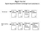
- a meter reading server 1 is connected to the telephone network 2, to enable it to make meter reading calls to a subscriber 3. Such calls pass via a local exchange 4, then through the network to an exchange 5 local to the subscriber, which connects the call with the subscriber.
- a special card 6 is provided, for no-ring call processing. At the exchange, outputs from this card are combined with outputs from a line card 7 for processing normal calls.
- the additional card enables different alerting tones to be sent to the subscriber, to enable equipment at the subscriber end to distinguish between no-ring meter calls, and normal telephone calls.
- a telemetry unit 9 answers only the no-ring calls, and transmits readings from meters 10.
- the ordinary phone 8 can be used as normal, unaffected by the meter reading transmission equipment and calls.
- a normal call using British Telecom standards includes a loop reversal stage 11, followed by alert tones fx and fy at step 12, for a given period, then data transmission in FSK form at step 13, maybe including calling line identity information. Finally, ring cadences occur at step 14.
- the system described enables the advantages of no-ring calls to be achieved for reading meters.
- the network 2 may be arranged to transmit calling line identity information at the time of setting up the call.
- the normal call processing card 7 of figure 1 would be arranged to transmit the CLI data.
- the terminal detects alert tones.
- the FSK data including the CLI is detected at step 31, and the ring cadence is detected at step 32.
- Caller number and name may be displayed if the terminal has a display, at step 33.
- Another feature which may use the CLI information is call screening.
- the terminal may check if the calling line number is to be screened out. As appropriate, the ringer is operated at step 34, and answering of the call is carried out when the subscriber picks up at step 35.
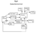
- FIG 4 shows in schematic form features of a conventional subscriber terminal such as the ordinary phone 8 of figure 1.
- An example of such a terminal is the C9316 designed and manufactured by Nortel.
- a line interface 40 interfaces with the line to the exchange.
- Tone detect circuitry 41 is provided for detecting the alert tone.
- FSK decoding is carried out by part 42.
- Ring cadence detection is carried out by part 43.
- the latter 3 parts feed a processor 44 which controls a display 45, a keyboard 46, and a ringer 47.
- a DTMF generator is provided for outputting dialling tones.
- the handset 49 has a link to speech circuitry 50, controlled by the processor 44, and, under the control of the processor 44, may output speech signals directly to the line interface, and may receive speech signals directly from the line interface.
- Such a terminal is capable of being adapted for use with various different signal sequence formats by changing the firmware of the processor 44.
- Figure 2 shows a British Telecom specification CLI system.
- CLI protocols such as the CATV protocol, ETSI protocols, and the Belcore protocol.
- the meter reading system shown in figure 1 is not easily adaptable for use with exchanges using protocols other than British Telecom protocols, and is inflexible once installed, because changes would require modifications at the local exchange.
- the method also comprises the step of answering the call using the interface unit, wherein the data transmitting step is carried out within the same call.
- the data transmitting step is carried out within the same call.
- CLI information is transmitted while the receiver is on-hook. Answering the call and sending the data in the same call facilitates rapid data transmission and enables it to be carried out with minimal equipment at the data source end.
- the cost of the telephone call can be borne by the calling party, rather than the end user.
- ringing is prevented when the call is answered. If ringing is prevented, calls can be made without disturbance to anyone at the data source end. Calls can be made at any time of day or night. This may be particularly useful for calls to domestic premises.
- the data is transmitted from the interface unit to the network using DTMF tones.
- DTMF tones enables extremely reliable transmission with minimal additional equipment at the data source end.
- Compatibility with ASDI which also uses DTMF may enable the method to be used with ASDI based systems.
- the calling party comprises a central server, and a plurality of data sources are accessed using different telephone calls in sequence from the calling party.
- a central server may quickly access data from widely separated locations securely and with inexpensive and standard, general availability equipment.
- the data relates to household equipment.
- monitoring of such equipment may be carried out remotely using inexpensive equipment, and with minimal disturbance to the occupants.
- the source of the data comprises a utility meter.
- Utility meters need to be read periodically. This can now be done with inexpensive hardware, low running and transmission costs, and minimal disturbance to utility customers.
- the data comprises data from a plurality of meters. Little additional hardware is required to read multiple meters at the same location using the same telephone line. Even the same call can be used, to minimise running costs.
- the method also comprises the step of using the interface unit to count pulses from the meter, and the data transmitted comprises counts of the pulses. Having the interface unit count pulses enables it to be used with a wide range of meters. If the counts are transmitted without interpretation, then changes in meaning of the counts, such as changes in tariff, can be handled centrally. Thus the need to upgrade many interface units in the field can be avoided.
- the interface unit is integrated into a telephone. Integrating the interface unit enables the amount of hardware to be minimised. This particularly important for the equipment at the data source side, for applications in which multiple data sources need to be accessed. For household use it is more convenient and costs may be reduced as some parts, such as microprocessor DTMF generator and CLI detection components may be used for two purposes to avoid duplication.
- a system for remotely accessing data using a telephone network having a calling line identity transmission facility comprising:
- an interface unit for transmitting data over a telephone network having a calling line identity transmission facility comprising:
- a device for remotely accessing data relating to household equipment, transmitted by an interface unit comprising:
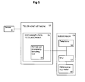
- FIG. 5 shows a remote access arrangement according to the invention.
- a server 51 initiates telephone calls through the telephone network 52 to reach a data source, in this case shown at the subscriber's location 53.
- the network includes an exchange 54 local to the subscriber. Calls from the server are passed to this exchange, and connected with the subscriber using normal call processing functions 55, including CLI.
- an interface unit MIU, 57 detects whether the calling line identity is a recognised identity, corresponding to the server 51. If not, the call is left for the ordinary telephone 56 to answer.
- the interface unit 57 may be on its own dedicated line, instead of sharing a line with the ordinary telephone 56.
- the interface unit transmits data from a data source, such as a meter 58, back to the server 51.
- the data could be transmitted as part of a separate phone call, or by a separate route, or even to a different server administered by the same calling party.
- the data could be transmitted in some other form rather than by the telephone network, eg radio transmission or power line data transmission.
- the interface unit can be arranged to respond to such different protocols, to enable the interface unit to work almost anywhere, without requiring expensive, inflexible changes at the exchange side.
- CLI may be more secure than relying on alert tones alone. Alert tones for meter reading could be triggered by an unauthorised person if they know the corresponding line access numbers. In contrast, using CLI information means the security relies on the calling number not the receiving number. It is easier to control the access to calling number since it is embedded in the network.
- a call is initiated to the interface unit.
- the interface unit detects whether calling line identity information is recognised. If so, the interface unit transmits the data to the calling party at step 62.
- the detailed examples relate to meter reading, but clearly the method is of broader applicability. For example, other household equipment could be monitored periodically for maintenance purposes. Security devices such as cameras and other detectors could be monitored remotely. Integration with home automation systems would be easy to implement.
- the interface unit at the data source side will now be described in more detail for the meter reading example.
- the unit will be connected to the subscriber line using a line interface 40.
- Tone detect circuitry 41, FSK decode circuitry 42, and DTMF generator circuitry 48 may be the same as those provided in the known subscriber terminal unit described with reference to figure 4.
- the processor 44 may be the same, though with different or enhanced firmware.
- the unit will be connected to the meter or meters, and if connected to pulse outputs of a meter, it will maintain a rolling count of the pulses received.
- the processor 44 may perform a high level of debouncing of the signals, to protect against false triggering within the electrical wiring.
- the interface unit On receipt of a call to the interface unit, it will decode the calling party's CLI and then either answer the call immediately, or allow the call to be handled as a normal telephone call to another telephone set on the same line.
- the tone detect and FSK decode circuitry in the interface unit function essentially as in the conventional terminal.
- the processor 44 will then determine if the decoded CLI information from the FSK decoder 42, corresponds to a predetermined calling line identity. A number of such predetermined identities may be set up during configuration of the interface unit. Provision may be made to change these predetermined numbers, or add to them, remotely, perhaps with some form of security, such as password protection, to prevent inadvertent or malicious changes.
- the processor then sends the meter pulse counts to the line using DTMF signalling typically at a rate of 10-30 digits per second.
- DTMF is capable of transmitting at 50 digits per second. A slower rate enables higher security. This may be required for utility metering where bills will be generated from the data.
- a defined protocol could be used, or the server could request a particular protocol be used at the time of setting up the meter reading call.
- DTMF decoding cards or devices for use with personal computers are widely available.
- the processor needs to react quickly enough to the CLI information from the FSK decoder, to answer the call, and prevent ringing occurring.
- the interface unit is also in control of the termination of the call. When it has sent all necessary data, preceded by appropriate headers, and followed by appropriate terminators, the interface unit will return the telephone line to the idle, on-hook, off-line status, ready to receive a further call. Typically, a data transfer may take several seconds to complete, according to how many meters are connected, and according to how many separate counts during separate tariff periods are made for each meter.
- the interface unit fails to recognise the CLI, it will conclude that the call is not a meter reading call, and it will not interrupt the call.
- the interface unit For regulatory requirements, when using a subscriber's telephone line for data reading applications, priority must be given to outgoing telephone calls, eg to permit emergency calls to be made at any time. Therefore the interface unit must detect the occurrence of a phone on the same line going off-hook. In the interface unit, the processor can be arranged to drop the data call using the line interface 40, and restore the line condition to dial tone.
- Figure 8 shows a possible interface from the interface unit to the meter.
- the meter gives an opto-isolated pulse output.
- One line is fed to ground, in the interface unit, while the other is fed to the micro-processor via a pull up resister R, and a series current limiting resister.
- the meter interface unit could be incorporated into a customer's telephone set, to avoid duplication of the line interface, the tone detect circuitry, the FSK decode circuitry, the DTMF generator, and the processor. Only firmware changes, and hardware changes to provide the interface with the meter or meters, would be necessary.
- a pulse counter can be implemented in the firmware. No resetting would be needed, the counter can be allowed to wrap around. Tamper proofing features can be provided at the interface unit. Further measures such as fraud detection based on the usage patterns could be incorporated at the interface unit or in the server.
- the interface unit can be provided as a separate stand alone item, to plug into the domestic phone socket . It would need no user accessible functions, buttons or display, and could be connected to the meter and be low cost and very unobtrusive. If it were integrated directly into the meter, there would be less opportunity for tampering since the connection between the data source and the telephone interface would be inaccessible. Hardware costs could be reduced.
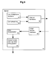
- Figure 9 shows in schematic form the basic functions of the server. It may take the form of a personal computer with a facility such as communications cards, for dialling out to the public telephone network, and monitoring DTMF tones on the line, from the interface unit.
- a facility such as communications cards, for dialling out to the public telephone network, and monitoring DTMF tones on the line, from the interface unit.
- the functions of the server could be incorporated into a mobile phone, and the results of the monitoring could be displayed on the mobile phone.
- the server needs a list of telephone numbers 91, and a call scheduling function 90, to cycle through the list of numbers on a round robin, or periodic basis. It also needs to be able to manage special one off meter readings, for situations such as moving house.
- Dial out hardware 92 will be controlled by the call scheduling function 90.
- DTMF decoding hardware 93 will provide a stream of data corresponding to each successful call.
- a data interpretation function 94 may also be provided at the server, or elsewhere. Finally, the results of the data interpretation function will be transmitted onwards, for example to a billing system, as shown by item 95.
- the server fails to read a meter in its schedule, it will create a separate list of meters it failed to read. Once it has finished its schedule of meters it will cycle through the list of meters it failed to read earlier, until they are all read, or a time out is triggered. An operator may be alerted of failure to read a meter after repeated attempts.
- Figure 10 shows the data interpretation function 94 in schematic form in more detail.
- the raw data from the DTMF decode hardware 93 will contain headers and be in a predetermined format, which may be specific to the subscriber being called, according to how many meters he has connected, and according to which tariff options he may have taken up. Accordingly, header and format details 100 may need to be stored for each subscriber to enable the raw data to be interpreted, to determine at item 101 counts for each meter.
- the counts may be converted into a billing data file, or files, to be sent to each utility billing system.
- a billing data file or files
- the counts may be converted into billable amounts, such as kilowatt hours, or even converted into financial terms, at step 103.
- the interface unit performs little processing or conversion of data. It is necessary to store counts of pulses if the telephone line is to be used only sparingly. If conversion and processing is carried out at the server, it is easier to update or change the processing to suit new tariffs or different types of meters, as there will be many more interface units than servers, and it would be more difficult to test any changes made, if the interface units are installed in the field.
- servers could download information to interface units, for example changing times for multiple tariff meters, or for controlling other equipment.
- interface units could be used for home automation/control purposes. Since it uses DTMF tones, in common with ADSI (analogue display services interface) equipment, it could be integrated into such systems relatively easily.
- the interface unit can be arranged to operate with a number of different calling parties and to distinguish between them. Different data may be transmitted depending on which calling party is recognised. For example, different utilities may have their own servers yet use a common interface unit at the users premises. The interface unit could be arranged to send only relevant data to each server.
- the interface unit could be arranged to receive only from a nominated mobile phone for example, which would act as the server.
- the phone 110 may be the subscriber's own mobile phone, or a central security office, which would contact the subscriber, or appropriate agencies to deal with anomalous data readings. This office or user's phone 110 initiates data reading calls as described above for meter readings.
- An interface unit 111 at the subscriber's location recognises only predetermined CLls corresponding to the security office, or the mobile phone 110 of the user.
- the interface unit In response to the detailed CLI, if authorised, the interface unit sends data from household equipment, or alarm system 112.
- the data could be received from such equipment in the form of a digital code indicating the status of the equipment.
- No counter would be needed in the interface unit, though if a counter were to be used, the household equipment could be arranged to provide pulse type data corresponding to meter outputs.
- the interface unit or the server could be arranged to decode the digital code or the count value, to indicate equipment status.
Landscapes
- Engineering & Computer Science (AREA)
- Signal Processing (AREA)
- Selective Calling Equipment (AREA)
- Telephonic Communication Services (AREA)
- Arrangements For Transmission Of Measured Signals (AREA)
Applications Claiming Priority (4)
| Application Number | Priority Date | Filing Date | Title |
|---|---|---|---|
| US865488 | 1986-05-21 | ||
| GB9624960 | 1996-11-29 | ||
| GB9624960A GB2319925A (en) | 1996-11-29 | 1996-11-29 | Remote data access |
| US86548897A | 1997-05-29 | 1997-05-29 |
Publications (1)
| Publication Number | Publication Date |
|---|---|
| EP0845896A1 true EP0845896A1 (fr) | 1998-06-03 |
Family
ID=26310528
Family Applications (1)
| Application Number | Title | Priority Date | Filing Date |
|---|---|---|---|
| EP97308978A Withdrawn EP0845896A1 (fr) | 1996-11-29 | 1997-11-07 | Accès de données à distance par téléphone |
Country Status (3)
| Country | Link |
|---|---|
| EP (1) | EP0845896A1 (fr) |
| JP (1) | JPH10190857A (fr) |
| CA (1) | CA2220802A1 (fr) |
Cited By (4)
| Publication number | Priority date | Publication date | Assignee | Title |
|---|---|---|---|---|
| WO2000035177A1 (fr) * | 1998-12-07 | 2000-06-15 | Telspec Europe Ltd. | Systeme de gestion a distance pour materiel electronique |
| EP1187407A2 (fr) * | 2000-09-08 | 2002-03-13 | Telerian Systems Limited | Utensile ménager internet |
| EP1217475A2 (fr) * | 2000-12-13 | 2002-06-26 | Lg Electronics Inc. | Appareil et méthode pour commander à distance des appareils ménagers |
| WO2003025875A1 (fr) * | 2001-09-21 | 2003-03-27 | Sydkraft Ab | Terminal, serveur, procede et accessoire pour la distribution a distance de services d'information |
Citations (2)
| Publication number | Priority date | Publication date | Assignee | Title |
|---|---|---|---|---|
| US5381462A (en) * | 1992-05-29 | 1995-01-10 | Datran Systems Corporation | Utility monitor communications systems |
| US5452343A (en) * | 1994-06-28 | 1995-09-19 | At&T Corp. | Telemetry access arrangement |
-
1997
- 1997-11-07 EP EP97308978A patent/EP0845896A1/fr not_active Withdrawn
- 1997-11-12 CA CA 2220802 patent/CA2220802A1/fr not_active Abandoned
- 1997-11-27 JP JP32676697A patent/JPH10190857A/ja active Pending
Patent Citations (2)
| Publication number | Priority date | Publication date | Assignee | Title |
|---|---|---|---|---|
| US5381462A (en) * | 1992-05-29 | 1995-01-10 | Datran Systems Corporation | Utility monitor communications systems |
| US5452343A (en) * | 1994-06-28 | 1995-09-19 | At&T Corp. | Telemetry access arrangement |
Cited By (6)
| Publication number | Priority date | Publication date | Assignee | Title |
|---|---|---|---|---|
| WO2000035177A1 (fr) * | 1998-12-07 | 2000-06-15 | Telspec Europe Ltd. | Systeme de gestion a distance pour materiel electronique |
| EP1187407A2 (fr) * | 2000-09-08 | 2002-03-13 | Telerian Systems Limited | Utensile ménager internet |
| EP1187407A3 (fr) * | 2000-09-08 | 2002-07-17 | Telerian Systems Limited | Utensile ménager internet |
| EP1217475A2 (fr) * | 2000-12-13 | 2002-06-26 | Lg Electronics Inc. | Appareil et méthode pour commander à distance des appareils ménagers |
| EP1217475A3 (fr) * | 2000-12-13 | 2003-02-05 | Lg Electronics Inc. | Appareil et méthode pour commander à distance des appareils ménagers |
| WO2003025875A1 (fr) * | 2001-09-21 | 2003-03-27 | Sydkraft Ab | Terminal, serveur, procede et accessoire pour la distribution a distance de services d'information |
Also Published As
| Publication number | Publication date |
|---|---|
| CA2220802A1 (fr) | 1998-05-29 |
| JPH10190857A (ja) | 1998-07-21 |
Similar Documents
| Publication | Publication Date | Title |
|---|---|---|
| US5809125A (en) | Method and apparatus for intercepting potentially fraudulent telephone calls | |
| EP0474407B1 (fr) | Système d'accès pour télémétrie | |
| US5394461A (en) | Telemetry feature protocol expansion | |
| US4794642A (en) | Call screening in a public telephone station | |
| US5022067A (en) | Telephone call security system | |
| US5737400A (en) | Telecommunications system for accessing subscriber premises equipment using ring suppression | |
| JP2981075B2 (ja) | 通信方法および交換機 | |
| CA1288152C (fr) | Prevention de l'emploi frauduleux d'un telephone public | |
| US5243644A (en) | Telemetry access arrangement | |
| EP0755602B1 (fr) | Systeme de telemesure | |
| US5655011A (en) | Selection of terminal equipment in response to a data message received during silent intervals of ringing | |
| US5812650A (en) | Method and apparatus for intercepting potentially fraudulent | |
| US6442264B1 (en) | Telephone call router for transferring data to and from data collection apparatus | |
| EP0845896A1 (fr) | Accès de données à distance par téléphone | |
| CA2257490A1 (fr) | Procede et dispositif de telemesure | |
| GB2319925A (en) | Remote data access | |
| EP0433153B1 (fr) | Terminal de télécommunication et de gestion connectable au réseau téléphonique et appareil d'appel automatique d'un tel terminal | |
| CN1171434C (zh) | 智能网业务电话终端 | |
| AU2146295A (en) | Telecommunications networks | |
| JP3367032B2 (ja) | 料金徴収式電話機 | |
| CA2249711A1 (fr) | Envoi de messages par rtpc | |
| JPH10155018A (ja) | 電話機 | |
| WO2004107720A1 (fr) | Procede et moyen permettant d'administrer des communications sur une ligne | |
| CA2242272A1 (fr) | Circulation de messages a l'aide des renseignements d'un afficheur | |
| HU214534B (hu) | Eszközkészlet távközlési hálózatok központi berendezéseihez jeltovábbító vezeték útján csatlakoztatott szolgáltató készülékek jogosulatlan használatának megszüntetésére |
Legal Events
| Date | Code | Title | Description |
|---|---|---|---|
| PUAI | Public reference made under article 153(3) epc to a published international application that has entered the european phase |
Free format text: ORIGINAL CODE: 0009012 |
|
| AK | Designated contracting states |
Kind code of ref document: A1 Designated state(s): BE DE FR GB NL SE |
|
| AX | Request for extension of the european patent |
Free format text: AL;LT;LV;MK;RO;SI |
|
| 17P | Request for examination filed |
Effective date: 19981203 |
|
| AKX | Designation fees paid |
Free format text: BE DE FR GB NL SE |
|
| RBV | Designated contracting states (corrected) |
Designated state(s): BE DE FR GB NL SE |
|
| STAA | Information on the status of an ep patent application or granted ep patent |
Free format text: STATUS: THE APPLICATION HAS BEEN WITHDRAWN |
|
| 18W | Application withdrawn |
Withdrawal date: 19990309 |