EP0845799B1 - Elektrode - Google Patents
Elektrode Download PDFInfo
- Publication number
- EP0845799B1 EP0845799B1 EP97308618A EP97308618A EP0845799B1 EP 0845799 B1 EP0845799 B1 EP 0845799B1 EP 97308618 A EP97308618 A EP 97308618A EP 97308618 A EP97308618 A EP 97308618A EP 0845799 B1 EP0845799 B1 EP 0845799B1
- Authority
- EP
- European Patent Office
- Prior art keywords
- aperture
- suppression electrode
- electrode
- suppression
- constructed
- Prior art date
- Legal status (The legal status is an assumption and is not a legal conclusion. Google has not performed a legal analysis and makes no representation as to the accuracy of the status listed.)
- Expired - Lifetime
Links
Images
Classifications
-
- H—ELECTRICITY
- H01—ELECTRIC ELEMENTS
- H01J—ELECTRIC DISCHARGE TUBES OR DISCHARGE LAMPS
- H01J37/00—Discharge tubes with provision for introducing objects or material to be exposed to the discharge, e.g. for the purpose of examination or processing thereof
- H01J37/30—Electron-beam or ion-beam tubes for localised treatment of objects
- H01J37/317—Electron-beam or ion-beam tubes for localised treatment of objects for changing properties of the objects or for applying thin layers thereon, e.g. for ion implantation
- H01J37/3171—Electron-beam or ion-beam tubes for localised treatment of objects for changing properties of the objects or for applying thin layers thereon, e.g. for ion implantation for ion implantation
-
- H10P30/20—
-
- H—ELECTRICITY
- H01—ELECTRIC ELEMENTS
- H01J—ELECTRIC DISCHARGE TUBES OR DISCHARGE LAMPS
- H01J37/00—Discharge tubes with provision for introducing objects or material to be exposed to the discharge, e.g. for the purpose of examination or processing thereof
- H01J37/02—Details
- H01J37/04—Arrangements of electrodes and associated parts for generating or controlling the discharge, e.g. electron-optical arrangement or ion-optical arrangement
- H01J37/08—Ion sources; Ion guns
-
- H—ELECTRICITY
- H01—ELECTRIC ELEMENTS
- H01J—ELECTRIC DISCHARGE TUBES OR DISCHARGE LAMPS
- H01J2237/00—Discharge tubes exposing object to beam, e.g. for analysis treatment, etching, imaging
- H01J2237/04—Means for controlling the discharge
- H01J2237/045—Diaphragms
Definitions
- This invention is related in general to the field of semiconductor processing apparatus. More particularly, the invention is related to an ion implantation suppression electrode assembly.
- Ion implantation is an important processing step in manufacturing semiconductor devices.
- a beam of impurity ions is accelerated to kinetic energies ranging from several keV to several MeV and directed onto the surface of the semiconductor.
- a typical ion implanter ionizes the desired impurity gas in an arc chamber and the ions are extracted by an energized extraction electrode assembly into an acceleration tube toward the semiconductor.
- the extraction electrode assembly typically includes two electrodes, a suppression electrode and an extraction electrode.
- ions are drawn out of the arc chamber or ion source, they pass through an aperture in the suppression electrode and toward an aperture in the extraction electrode. The majority of the ions pass through the extraction electrode aperture, but some strike the extraction electrode and generate secondary electrons. These secondary electrons are drawn by the highly positive source and accelerate toward it. The striking of the secondary electrons on the ion source would have resulted in the release of X-rays. However, these secondary electrons are stopped by the suppression electrode so that the generation of X-rays is greatly minimized.
- the extraction electrode assembly In addition to extracting the ions from the arc chamber, the extraction electrode assembly further performs beam steering and focusing functions.
- the extraction electrode can be tilted and moved relative to the stationary ion source to center and focus the ion beam.
- the aperture is worn down quickly.
- a worn aperture may no longer have a well-defined opening and cannot steer and focus the ion beam in an effective manner.
- the suppression electrode is manufactured from a fragile material, typically graphite, careless mishandling also can easily damage the aperture and the electrode itself. Carelessness during the alignment process while installing the suppression electrode also may chip the aperture. When the aperture is damaged, the entire suppression electrode must be replaced, which is costly. Further, because of the porous and hydrophilic properties of graphite, substantial time is required to completely pump out the extraction chamber and out gas the suppression electrode after maintenance and servicing.
- EP-A-0 557 067 discloses an ion beam source which includes multiple apertures bounded in close proximity by an extraction electrode for extracting positively charged ions from the source. Ions exiting the source combine downstream to form a broad beam. Individual electrodes in close proximity to the extraction electrode can be biased to either inhibit or allow backstreaming of neutralizing electrons from beam portions close to the source back to the extraction electrode. An isolation plate separates beam portions in close proximity to the extraction electrode to inhibit beam cross-talk and an additional suppression electrode common to all beam portions is controllably biased to further enhance control over beam portion intensity.
- a suppression electrode assembly is provided which eliminates or substantially reduces the disadvantages associated with prior suppression electrodes used in ion implanters.
- the present invention provides a suppression electrode having an aperture for the passage of accelerated ions from an ion source to a target, said suppression electrode being suitable for stopping secondary electrons and comprising a suppression electrode plate; characterized in that: said suppression electrode plate has an aperture seat with an opening defined therein; and in that said suppression electrode also comprises an aperture insert having an elongated slit which defines said aperture, said aperture insert being slidably engageable with said aperture seat such that the said elongated slit is arranged to be in general alignment with said opening in said aperture seat.
- the suppression electrode assembly may comprise an electrode suppression plate constructed of a material having substantial strength and durability.
- the aperture insert may be constructed from graphite.
- a technical advantage is the durability of the suppression electrode and the disposability of the aperture insert. When worn or damaged beyond acceptable limits, the fragile aperture inserts may be replaced easily with a new one.
- the suppression electrode plate is constructed from durable material such as stainless steel, it is substantially more resistant to possible damage caused by mishandling. Further, when the suppression electrode is constructed from a less porous and hydrophilic material than graphite, considerably less time is required to evacuate the extraction chamber to achieve vacuum after maintenance and servicing.
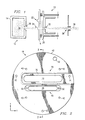
- FIGURES 1-6 The preferred embodiment(s) of the present invention is (are) illustrated in FIGURES 1-6, like reference numerals being used to refer to like and corresponding parts of the various drawings.
- an extraction electrode assembly 10 is shown positioned in front of an ion source 12.
- Ion source 12 is an arc chamber 14 containing an highly energized and ionized impurity gas 16, such as boron.
- Extraction electrode assembly 10 includes a first electrode 18 placed at a predetermined distance in front of arc chamber 14, and a second electrode 20 placed behind first electrode 18.
- First electrode 18 is commonly called the suppression electrode
- second electrode 20 is commonly called the extraction electrode.
- Suppression electrode 18 may have more than one aperture to allow the passage of extracted ions at different energies.
- suppression electrode 18 When suppression electrode 18 has two apertures 22 and 24, it is sometimes referred to as a dual-slit electrode, such as one used in model NV-20A manufactured by Eaton Corporation, Beverly, Massachusetts.
- suppression electrode 18 is constructed out of an inert but fragile material, such as graphite.
- extraction electrode 20 is charged and maintained at a voltage significantly lower or more negative than the arc chamber potential to attract and extract the positive ions 16 out of arc chamber 14 through an arc chamber aperture 30.
- the ions then pass through aperture 22 or 24 in suppression electrode 18 and pass through an aperture 32 in extraction electrode 20.
- Some of the ions strike electrode 20 and generate secondary electrons. These electrons are stopped from rebounding and hitting arc chamber 14 by suppression electrode 18, which is maintained at a more negative potential than extraction electrode 20.
- the X-rays that would otherwise have been generated by the secondary electrons hitting arc chamber 14 are thus substantially reduced or eliminated.
- the resultant stream of extracted ions form an ion beam 36, which travels through downstream equipment of the ion implanter toward the target semiconductor (not shown).
- Extraction electrode assembly 10 can be displaced or moved along three axis to steer and focus ion beam 36 through a source housing aperture 38, so that the majority of the ions pass through aperture 38 and are in good alignment with downstream equipment in the ion implanter.
- Suppression electrode 18 includes an electrode suppression plate 40 constructed from a material with suitable mechanical, chemical, and thermal properties. For example, it is desirable to use a material that does not warp or have high thermionic emissions when subjected to temperatures experienced in the extraction chamber.
- stainless steel has been selected as the material used to fashion electrode suppression plate 40 therefrom.
- Electrode suppression plate 40 constructed from stainless steel can withstand large forces and can be easily cleaned.
- Conventional electrode suppression plates 40 are constructed from graphite, which is fragile, easily contaminated, and more difficult to clean.
- Electrode suppression plate 40 preferably has a flat disc profile and includes a number of through holes 42 located at predetermined locations for receiving fasteners therethrough to securely hold electrode suppression plate 40 in extraction electrode assembly 10 (FIGURE 1). It is obvious that the number, location and size of through holes 42, some of which may be countersunk, is determined by the nature of the seat or fixture (not shown explicitly) that receives suppression electrode 18.
- a first seat 48 for a first aperture 46 may be provided.
- aperture 46 is for extracting ions biased at a first range of voltage potential, for example, voltage levels greater than 30 KeV.
- Aperture seat 48 may include one or more openings 50 for receiving fasteners (not shown) to secure the insert therein.
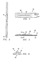
- FIGURES 4-6 are also provided.
- Aperture 70 includes an elongated opening 72 and at least one opening 74 for receiving a fastener (not shown).
- FIGURE 3 is a cross-sectional view of electrode suppression plate 40 along line 3-3 in FIGURE 2.
- Seat 76 extends to the perimeter of electrode suppression plate 40 to allow the aperture insert to be positioned in seat 76 by sliding it from the perimeter toward the center of plate 40.
- Aperture insert 80 includes a bottom plate 81 from which a generally domed aperture portion 86 arises.
- Bottom plate 81 is shaped and sized to slidably engage seat 76 formed in suppression electrode plate 40. It may be seen that aperture insert 80 may engage seat 76 from the perimeter of electrode suppression plate 40 and may be slid into seat 76. Once seated, aperture insert 80 cannot be removed by turning electrode suppression plate 40 upside down since the top lip of seat 76 is narrower than the bottom.
- At least one opening 82 is formed in bottom plate 81 of aperture insert, which corresponds in size and position with opening 74 formed in seat 76 for receiving a fastener.
- a fastener such as a bolt or screw
- Opening 74 may be countersunk.
- the desirable insert material preferably does not contain elements that are mobile in the semiconductor crystal lattice, such as chromium, nickel, and aluminum.
- aperture insert 80 is fashioned from graphite or any other suitable material that is not electrically active in silicon.
- Domed portion 86 of aperture insert 80 includes an elongated slit 84 of a predetermined width and length for the passage of accelerated ions from the ion source to their target.
- Domed portion 86 is substantially hollow with an elongated and domed void 90 that has a generally semi-circular cross-section. Void 90 echoes the shape of elongated slit 84 and is connected thereto, forming a continuous passageway through aperture insert 80.
- Dome portion 86 may further have a generally curved top surface 92 having a predetermined degree of curvature. This curvature is again echoed in the ceiling of void 90.
- aperture insert 80 may be easily replaced by a new insert when it is worn or damaged beyond the required specifications.
- Electrode suppression plate 40 because of the strength and more durable properties of stainless steel, can be used and reused many times as a more permanent fixture with replacement aperture inserts.Aperture inserts may be replaced without the removal and realignment of the entire suppression electrode 18, thus reducing the likelihood of contamination and increase the efficiency and speed of system maintenance. Less time and effort is also required to pump out the extraction chamber because the electrode suppression plate is fashioned from a less porous and hydrophilic material than graphite, such as stainless steel. As a result, the cost of operating the ion implanter is significantly reduced.
Landscapes
- Chemical & Material Sciences (AREA)
- Analytical Chemistry (AREA)
- Electron Sources, Ion Sources (AREA)
- Electrical Discharge Machining, Electrochemical Machining, And Combined Machining (AREA)
- Physical Vapour Deposition (AREA)
Claims (8)
- Unterdrückungselektrode (18) mit einer Öffnung (22, 24) zum Hindurchtreten beschleunigter Ionen von einer Ionenquelle (12) zu einem Target, wobei die Unterdrückungselektrode zum Ausbremsen von Sekundärelektronen geeignet ist und eine Unterdrückungselektrodenplatte (40) aufweist,
dadurch gekennzeichnet, daß
die Unterdrückungselektrodenplatte einen Öffnungssitz (76) mit einem darin ausgebildeten Öffnungsloch (72) aufweist und daß die Unterdrückungselektrode auch einen Öffnungseinsatz (80) mit einem langgestreckten Schlitz (84) aufweist, der die Öffnung (22, 24) bildet, wobei der Öffnungseinsatz (80) durch Verschieben in Eingriff mit dem Öffnungssitz (76) gebracht werden kann, so daß der langgestreckte Schlitz (84) so eingerichtet wird, daß er im wesentlichen mit dem Öffnungsloch (72) in dem Öffnungssitz ausgerichtet ist. - Unterdrückungselektrode (18) nach Anspruch 1, wobei die Unterdrückungselektrodenplatte (40) aus einem Metall besteht.
- Unterdrückungselektrode (18) nach Anspruch 1 oder 2, wobei die Unterdrückungselektrodenplatte (40) aus Edelstahl besteht.
- Unterdrückungselektrode (18) nach einem der vorhergehenden Ansprüche, wobei der Öffnungseinsatz (80) aus einem Material besteht, das in Silicium nicht elektrisch aktiv ist.
- Unterdrückungselektrode (18) nach einem der vorhergehenden Ansprüche, wobei der Öffnungseinsatz (80) aus Graphit besteht.
- Unterdrückungselektrode (18) nach einem der vorhergehenden Ansprüche, wobei der Öffliungseinsatz (80) aufweist:eine Bodenplatte (81), die so eingerichtet ist, daß sie durch Verschieben in Eingriff mit dem Öffnungssitz (76) gebracht werden kann, einen kuppelförmigen Abschnitt (86), der einen langgestreckten Freiraum (90) aufweist und so angeordnet ist, daß er sich im wesentlichen über die Länge der Öffnung (72) in dem Öffhungssitz (76) erstreckt, wobei der kuppelförmige Abschnitt weiterhin den langgestreckten Schlitz (84) durch den oberen Teil des koppelförmigen Abschnitts, der mit dem langgestreckten Freiraum (90) in Verbindung steht und im wesentlichen mit diesem ausgerichtet ist, aufweist.
- Unterdrückungselektrode (18) nach Anspruch 6, wobei sich die Bodenplatte (81), wenn sie in den Öffhungssitz (76) eingesetzt ist, bis zur äußeren Begrenzung der Unterdrückungselektrodenplatte (40) erstreckt.
- Unterdrückungselektrode (18) nach einem der vorhergehenden Ansprüche, wobei die Unterdrückungselektrodenplatte (40) aus einem Material besteht, das nach seiner Festigkeit und Haltbarkeit ausgewählt ist.
Applications Claiming Priority (2)
| Application Number | Priority Date | Filing Date | Title |
|---|---|---|---|
| US3040596P | 1996-10-29 | 1996-10-29 | |
| US30405P | 1996-10-29 |
Publications (3)
| Publication Number | Publication Date |
|---|---|
| EP0845799A2 EP0845799A2 (de) | 1998-06-03 |
| EP0845799A3 EP0845799A3 (de) | 2000-09-20 |
| EP0845799B1 true EP0845799B1 (de) | 2003-07-09 |
Family
ID=21854049
Family Applications (1)
| Application Number | Title | Priority Date | Filing Date |
|---|---|---|---|
| EP97308618A Expired - Lifetime EP0845799B1 (de) | 1996-10-29 | 1997-10-28 | Elektrode |
Country Status (6)
| Country | Link |
|---|---|
| US (1) | US5959396A (de) |
| EP (1) | EP0845799B1 (de) |
| JP (1) | JPH10144250A (de) |
| KR (1) | KR19980033220A (de) |
| DE (1) | DE69723404T2 (de) |
| TW (1) | TW442852B (de) |
Families Citing this family (10)
| Publication number | Priority date | Publication date | Assignee | Title |
|---|---|---|---|---|
| US6291827B1 (en) * | 1999-03-26 | 2001-09-18 | Mosel Vitelic Inc. | Insulating apparatus for a conductive line |
| GB2367685B (en) * | 2000-07-26 | 2004-06-16 | Masslab Ltd | Ion source for a mass spectrometer |
| KR100712494B1 (ko) * | 2001-08-31 | 2007-05-02 | 삼성전자주식회사 | 이온주입장치의 레졸빙 어퍼쳐 |
| KR100551338B1 (ko) * | 2003-07-25 | 2006-02-09 | 동부아남반도체 주식회사 | 이온빔 발생장치의 일렉트로드 헤드 |
| US7145157B2 (en) * | 2003-09-11 | 2006-12-05 | Applied Materials, Inc. | Kinematic ion implanter electrode mounting |
| KR100510559B1 (ko) * | 2003-12-30 | 2005-08-26 | 삼성전자주식회사 | 이온 주입 장비의 매니퓰레이터 어셈블리 |
| KR100553716B1 (ko) * | 2004-08-02 | 2006-02-24 | 삼성전자주식회사 | 이온 주입 설비의 이온 소스부 |
| US20090101834A1 (en) * | 2007-10-23 | 2009-04-23 | Applied Materials, Inc. | Ion beam extraction assembly in an ion implanter |
| US20130045339A1 (en) * | 2011-08-15 | 2013-02-21 | Varian Semiconductor Equipment Associates, Inc. | Techniques for diamond nucleation control for thin film processing |
| US10714296B2 (en) * | 2018-12-12 | 2020-07-14 | Axcelis Technologies, Inc. | Ion source with tailored extraction shape |
Family Cites Families (5)
| Publication number | Priority date | Publication date | Assignee | Title |
|---|---|---|---|---|
| US4847504A (en) * | 1983-08-15 | 1989-07-11 | Applied Materials, Inc. | Apparatus and methods for ion implantation |
| GB8623453D0 (en) * | 1986-09-30 | 1986-11-05 | Tecvac Ltd | Ion implantation |
| DE3708716C2 (de) * | 1987-03-18 | 1993-11-04 | Hans Prof Dr Rer Nat Oechsner | Hochfrequenz-ionenquelle |
| US5218210A (en) * | 1992-02-18 | 1993-06-08 | Eaton Corporation | Broad beam flux density control |
| JP3054302B2 (ja) * | 1992-12-02 | 2000-06-19 | アプライド マテリアルズ インコーポレイテッド | イオン注入中の半導体ウェハにおける帯電を低減するプラズマ放出システム |
-
1997
- 1997-10-16 US US08/951,717 patent/US5959396A/en not_active Expired - Lifetime
- 1997-10-28 KR KR1019970055501A patent/KR19980033220A/ko not_active Withdrawn
- 1997-10-28 DE DE69723404T patent/DE69723404T2/de not_active Expired - Lifetime
- 1997-10-28 EP EP97308618A patent/EP0845799B1/de not_active Expired - Lifetime
- 1997-10-29 JP JP9297070A patent/JPH10144250A/ja active Pending
- 1997-11-21 TW TW086116240A patent/TW442852B/zh active
Also Published As
| Publication number | Publication date |
|---|---|
| EP0845799A3 (de) | 2000-09-20 |
| DE69723404D1 (de) | 2003-08-14 |
| US5959396A (en) | 1999-09-28 |
| TW442852B (en) | 2001-06-23 |
| JPH10144250A (ja) | 1998-05-29 |
| DE69723404T2 (de) | 2004-04-15 |
| EP0845799A2 (de) | 1998-06-03 |
| KR19980033220A (ko) | 1998-07-25 |
Similar Documents
| Publication | Publication Date | Title |
|---|---|---|
| TWI404106B (zh) | 離子植入系統、用於減少離子植入系統中的污染之裝置以及用於控制離子植入系統中的污染之方法 | |
| EP1981058B1 (de) | Ionenimplantationsvorrichtung und Ionenimplantationsverfahren | |
| US5343047A (en) | Ion implantation system | |
| US5026997A (en) | Elliptical ion beam distribution method and apparatus | |
| US8963107B2 (en) | Beam line design to reduce energy contamination | |
| EP0845799B1 (de) | Elektrode | |
| GB2390221A (en) | Ion beam neutralizer and method therefor | |
| US20080149826A1 (en) | Techniques for providing a ribbon-shaped gas cluster ion beam | |
| KR20170019386A (ko) | 텍스쳐링된 내부 표면들을 갖는 이온 주입 소스 | |
| JPH10330939A (ja) | イオン注入装置、二重排気チューブ組立体及びその交換方法 | |
| EP1314182B1 (de) | Vorrichtung und verfahren zum entfernen von, in einem ionenstrahl mitgeführten teilchen | |
| TWI396765B (zh) | 具有污染物收集表面的離子植入器 | |
| US20080203286A1 (en) | Apparatus and method for cooling ions | |
| JP5042451B2 (ja) | ビーム空間電荷中和装置及びこれを備えたイオン注入装置 | |
| US4471224A (en) | Apparatus and method for generating high current negative ions | |
| US7772576B2 (en) | Shielding assembly for semiconductor manufacturing apparatus and method of using the same | |
| US7928413B2 (en) | Ion implanters | |
| US20220115236A1 (en) | Method and apparatus to eliminate contaminant particles from an accelerated neutral atom beam and thereby protect a beam target | |
| JPS5827620B2 (ja) | イオン衝撃装置 | |
| US20100252746A1 (en) | End terminations for electrodes used in ion implantation systems | |
| US6084241A (en) | Method of manufacturing semiconductor devices and apparatus therefor | |
| CN112640025B (zh) | 离子植入机及离子植入设备 | |
| KR100774813B1 (ko) | 이온주입장치의 추출 전극 및 이온 빔 포커싱 방법 | |
| KR100735014B1 (ko) | 이온주입장치의 매니플레이터 | |
| CN111146068A (zh) | 清扫离子注入机束流通道的方法 |
Legal Events
| Date | Code | Title | Description |
|---|---|---|---|
| PUAI | Public reference made under article 153(3) epc to a published international application that has entered the european phase |
Free format text: ORIGINAL CODE: 0009012 |
|
| AK | Designated contracting states |
Kind code of ref document: A2 Designated state(s): DE FR GB IT NL |
|
| AX | Request for extension of the european patent |
Free format text: AL;LT;LV;RO;SI |
|
| PUAL | Search report despatched |
Free format text: ORIGINAL CODE: 0009013 |
|
| AK | Designated contracting states |
Kind code of ref document: A3 Designated state(s): AT BE CH DE DK ES FI FR GB GR IE IT LI LU MC NL PT SE |
|
| AX | Request for extension of the european patent |
Free format text: AL;LT;LV;RO;SI |
|
| 17P | Request for examination filed |
Effective date: 20010314 |
|
| AKX | Designation fees paid |
Free format text: DE FR GB IT NL |
|
| 17Q | First examination report despatched |
Effective date: 20011205 |
|
| RTI1 | Title (correction) |
Free format text: ELECTRODE |
|
| GRAH | Despatch of communication of intention to grant a patent |
Free format text: ORIGINAL CODE: EPIDOS IGRA |
|
| RTI1 | Title (correction) |
Free format text: ELECTRODE |
|
| GRAH | Despatch of communication of intention to grant a patent |
Free format text: ORIGINAL CODE: EPIDOS IGRA |
|
| GRAA | (expected) grant |
Free format text: ORIGINAL CODE: 0009210 |
|
| AK | Designated contracting states |
Designated state(s): DE FR GB IT NL |
|
| PG25 | Lapsed in a contracting state [announced via postgrant information from national office to epo] |
Ref country code: NL Free format text: LAPSE BECAUSE OF FAILURE TO SUBMIT A TRANSLATION OF THE DESCRIPTION OR TO PAY THE FEE WITHIN THE PRESCRIBED TIME-LIMIT Effective date: 20030709 Ref country code: IT Free format text: LAPSE BECAUSE OF FAILURE TO SUBMIT A TRANSLATION OF THE DESCRIPTION OR TO PAY THE FEE WITHIN THE PRESCRIBED TIME-LIMIT;WARNING: LAPSES OF ITALIAN PATENTS WITH EFFECTIVE DATE BEFORE 2007 MAY HAVE OCCURRED AT ANY TIME BEFORE 2007. THE CORRECT EFFECTIVE DATE MAY BE DIFFERENT FROM THE ONE RECORDED. Effective date: 20030709 |
|
| REG | Reference to a national code |
Ref country code: GB Ref legal event code: FG4D |
|
| REF | Corresponds to: |
Ref document number: 69723404 Country of ref document: DE Date of ref document: 20030814 Kind code of ref document: P |
|
| NLV1 | Nl: lapsed or annulled due to failure to fulfill the requirements of art. 29p and 29m of the patents act | ||
| ET | Fr: translation filed | ||
| PLBE | No opposition filed within time limit |
Free format text: ORIGINAL CODE: 0009261 |
|
| STAA | Information on the status of an ep patent application or granted ep patent |
Free format text: STATUS: NO OPPOSITION FILED WITHIN TIME LIMIT |
|
| 26N | No opposition filed |
Effective date: 20040414 |
|
| PGFP | Annual fee paid to national office [announced via postgrant information from national office to epo] |
Ref country code: GB Payment date: 20120925 Year of fee payment: 16 |
|
| PGFP | Annual fee paid to national office [announced via postgrant information from national office to epo] |
Ref country code: FR Payment date: 20121010 Year of fee payment: 16 Ref country code: DE Payment date: 20121031 Year of fee payment: 16 |
|
| GBPC | Gb: european patent ceased through non-payment of renewal fee |
Effective date: 20131028 |
|
| PG25 | Lapsed in a contracting state [announced via postgrant information from national office to epo] |
Ref country code: GB Free format text: LAPSE BECAUSE OF NON-PAYMENT OF DUE FEES Effective date: 20131028 |
|
| REG | Reference to a national code |
Ref country code: DE Ref legal event code: R119 Ref document number: 69723404 Country of ref document: DE Effective date: 20140501 |
|
| REG | Reference to a national code |
Ref country code: FR Ref legal event code: ST Effective date: 20140630 |
|
| PG25 | Lapsed in a contracting state [announced via postgrant information from national office to epo] |
Ref country code: FR Free format text: LAPSE BECAUSE OF NON-PAYMENT OF DUE FEES Effective date: 20131031 Ref country code: DE Free format text: LAPSE BECAUSE OF NON-PAYMENT OF DUE FEES Effective date: 20140501 |