EP0845721A1 - Numerical controller - Google Patents
Numerical controller Download PDFInfo
- Publication number
- EP0845721A1 EP0845721A1 EP97926268A EP97926268A EP0845721A1 EP 0845721 A1 EP0845721 A1 EP 0845721A1 EP 97926268 A EP97926268 A EP 97926268A EP 97926268 A EP97926268 A EP 97926268A EP 0845721 A1 EP0845721 A1 EP 0845721A1
- Authority
- EP
- European Patent Office
- Prior art keywords
- sequence
- program
- circuit
- storing
- sequence program
- Prior art date
- Legal status (The legal status is an assumption and is not a legal conclusion. Google has not performed a legal analysis and makes no representation as to the accuracy of the status listed.)
- Granted
Links
Images


Classifications
-
- G—PHYSICS
- G05—CONTROLLING; REGULATING
- G05B—CONTROL OR REGULATING SYSTEMS IN GENERAL; FUNCTIONAL ELEMENTS OF SUCH SYSTEMS; MONITORING OR TESTING ARRANGEMENTS FOR SUCH SYSTEMS OR ELEMENTS
- G05B19/00—Programme-control systems
- G05B19/02—Programme-control systems electric
- G05B19/18—Numerical control [NC], i.e. automatically operating machines, in particular machine tools, e.g. in a manufacturing environment, so as to execute positioning, movement or co-ordinated operations by means of programme data in numerical form
- G05B19/19—Numerical control [NC], i.e. automatically operating machines, in particular machine tools, e.g. in a manufacturing environment, so as to execute positioning, movement or co-ordinated operations by means of programme data in numerical form characterised by positioning or contouring control systems, e.g. to control position from one programmed point to another or to control movement along a programmed continuous path
-
- G—PHYSICS
- G05—CONTROLLING; REGULATING
- G05B—CONTROL OR REGULATING SYSTEMS IN GENERAL; FUNCTIONAL ELEMENTS OF SUCH SYSTEMS; MONITORING OR TESTING ARRANGEMENTS FOR SUCH SYSTEMS OR ELEMENTS
- G05B19/00—Programme-control systems
- G05B19/02—Programme-control systems electric
- G05B19/18—Numerical control [NC], i.e. automatically operating machines, in particular machine tools, e.g. in a manufacturing environment, so as to execute positioning, movement or co-ordinated operations by means of programme data in numerical form
- G05B19/406—Numerical control [NC], i.e. automatically operating machines, in particular machine tools, e.g. in a manufacturing environment, so as to execute positioning, movement or co-ordinated operations by means of programme data in numerical form characterised by monitoring or safety
- G05B19/4068—Verifying part programme on screen, by drawing or other means
-
- G—PHYSICS
- G05—CONTROLLING; REGULATING
- G05B—CONTROL OR REGULATING SYSTEMS IN GENERAL; FUNCTIONAL ELEMENTS OF SUCH SYSTEMS; MONITORING OR TESTING ARRANGEMENTS FOR SUCH SYSTEMS OR ELEMENTS
- G05B19/00—Programme-control systems
- G05B19/02—Programme-control systems electric
- G05B19/18—Numerical control [NC], i.e. automatically operating machines, in particular machine tools, e.g. in a manufacturing environment, so as to execute positioning, movement or co-ordinated operations by means of programme data in numerical form
- G05B19/414—Structure of the control system, e.g. common controller or multiprocessor systems, interface to servo, programmable interface controller
- G05B19/4148—Structure of the control system, e.g. common controller or multiprocessor systems, interface to servo, programmable interface controller characterised by using several processors for different functions, distributed (real-time) systems
-
- G—PHYSICS
- G05—CONTROLLING; REGULATING
- G05B—CONTROL OR REGULATING SYSTEMS IN GENERAL; FUNCTIONAL ELEMENTS OF SUCH SYSTEMS; MONITORING OR TESTING ARRANGEMENTS FOR SUCH SYSTEMS OR ELEMENTS
- G05B2219/00—Program-control systems
- G05B2219/30—Nc systems
- G05B2219/33—Director till display
- G05B2219/33102—Dnc and cnc combined
-
- G—PHYSICS
- G05—CONTROLLING; REGULATING
- G05B—CONTROL OR REGULATING SYSTEMS IN GENERAL; FUNCTIONAL ELEMENTS OF SUCH SYSTEMS; MONITORING OR TESTING ARRANGEMENTS FOR SUCH SYSTEMS OR ELEMENTS
- G05B2219/00—Program-control systems
- G05B2219/30—Nc systems
- G05B2219/33—Director till display
- G05B2219/33304—Display of diagnostic
-
- G—PHYSICS
- G05—CONTROLLING; REGULATING
- G05B—CONTROL OR REGULATING SYSTEMS IN GENERAL; FUNCTIONAL ELEMENTS OF SUCH SYSTEMS; MONITORING OR TESTING ARRANGEMENTS FOR SUCH SYSTEMS OR ELEMENTS
- G05B2219/00—Program-control systems
- G05B2219/30—Nc systems
- G05B2219/34—Director, elements to supervisory
- G05B2219/34348—Coordination of operations, different machines, robots execute different tasks
-
- G—PHYSICS
- G05—CONTROLLING; REGULATING
- G05B—CONTROL OR REGULATING SYSTEMS IN GENERAL; FUNCTIONAL ELEMENTS OF SUCH SYSTEMS; MONITORING OR TESTING ARRANGEMENTS FOR SUCH SYSTEMS OR ELEMENTS
- G05B2219/00—Program-control systems
- G05B2219/30—Nc systems
- G05B2219/34—Director, elements to supervisory
- G05B2219/34367—Interrupts, different tasks foreground, midground, background
-
- Y—GENERAL TAGGING OF NEW TECHNOLOGICAL DEVELOPMENTS; GENERAL TAGGING OF CROSS-SECTIONAL TECHNOLOGIES SPANNING OVER SEVERAL SECTIONS OF THE IPC; TECHNICAL SUBJECTS COVERED BY FORMER USPC CROSS-REFERENCE ART COLLECTIONS [XRACs] AND DIGESTS
- Y02—TECHNOLOGIES OR APPLICATIONS FOR MITIGATION OR ADAPTATION AGAINST CLIMATE CHANGE
- Y02P—CLIMATE CHANGE MITIGATION TECHNOLOGIES IN THE PRODUCTION OR PROCESSING OF GOODS
- Y02P90/00—Enabling technologies with a potential contribution to greenhouse gas [GHG] emissions mitigation
- Y02P90/02—Total factory control, e.g. smart factories, flexible manufacturing systems [FMS] or integrated manufacturing systems [IMS]
Definitions
- the present invention relates to a numerical control apparatus for controlling a machine tool or the like.
- a numerical control apparatus for controlling a machine tool or the like incorporates a programmable controller (hereinafter referred to as "PC") which performs sequence control by receiving an auxiliary function signals (M function signal, T function signal) transmitted from a numerical control section and signals (cycle start signal, feed hold signal or the like) transmitted from the machine, thereby performing control of the machine in cooperation with a processor of the numerical control section.
- PC programmable controller
- the sequence program of the peripheral device has less independency and therefore is needed to be interlocked with the operation of the CNC apparatus. For this reason, in order for the sequence program of the peripheral device to be executed by the PC incorporated into the CNC apparatus according the above method (1), it is necessary for the sequence program of the peripheral device to be incorporated into the sequence program specific to the PC in order to be connected therewith. Accordingly, the procedure for this incorporation becomes complex for a dealer or user other than a designer of the sequence program of the CNC apparatus in modifying or incorporating the sequence program of the peripheral device to be used as an option.
- the above method (2) is free of the problems with the above method (1).
- it becomes necessary to provide what is otherwise unnecessary such as a wiring for making connection between the PC incorporated into the CNC apparatus and an external programmable controller to the CNC apparatus, a main body of the external programmable controller, a power source for driving this main body, a locker for providing necessary space and the like.
- development procedure of the editing function, diagnosis function, etc. needed for developing the sequence program of the external programmable controller differs, there arises the problem such that the system development efficiency will decline.
- one embodiment of numerical control apparatus is equipped with storing means for storing a sequence program for performing sequence control of a machine to be numerically controlled and a sequence program for performing sequence control of a peripheral device operating in coordination with the machine, thereby performing sequence control and numerical control of the machine, as well as the sequence control of the peripheral device in coordination with the operation of the machine.
- another form of numerical control apparatus is equipped with storing means for storing a plurality of sequence programs, program executing means for executing a plurality of sequence programs, selecting means for selecting one of the plurality of the sequence programs, diagnosing means for displaying the contents and executed state of the selected sequence program, and editing means for performing editing and inputting/outputting of the selected sequence program.
- Still another form of numerical control apparatus is equipped with storing means for storing a sequence program for performing sequence control of a machine to be numerically controlled and a sequence program for performing sequence control of a peripheral device operating in coordination with the operation of the machine, program executing means for executing the respective sequence programs, signal transmitting/receiving means, for transmitting and receiving an interface signal between the numerical control section and the program executing means, designed to coordinate the numerical control of the machine with the execution of the sequence program for performing sequence control of the machine, signal transmitting/receiving means, for transmitting and receiving an interface signal, designed to coordinate the execution of the sequence program for performing sequence control of the machine with the execution of the sequence program for performing sequence control of the peripheral device, selecting means for selecting one of the sequence programs, diagnosing means for displaying the contents and the executed state of the selected sequence program, and editing means for performing editing and inputting/outputting of the selected sequence program.
- a plurality of the sequence programs are stored within the CNC apparatus and the respective sequence programs are designed to be executed in coordination with each other, so that both the sequence control of the machine to be numerically controlled and the sequence control of the peripheral device associated with the operation of this machine can be performed by the CNC apparatus alone.
- the respective sequence programs are independently stored but also inputted/outputted, editing and diagnosis of each sequence program can be performed selectively, so that there is no possibility such that, when modifying any one sequence program, the other sequence program is changed by mistake or the like. Therefore, the safety in this respect is ensured.
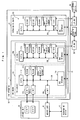
- the CNC apparatus 10 is provided with an extension PC board 12 as well as a CNC board 11.
- this CNC board 11 is provided with a CNC circuit 100 and a PC circuit 200 for performing sequence control of a main body of a machine tool.
- the extension PC board 12 is provided with a PC circuit 300 for performing sequence control of a peripheral device. That is, the CNC apparatus 10 of Fig. 1 differs from the conventional CNC apparatus in that it is equipped with the extension PC board 12.
- the PC circuit 200 for performing sequence control of the main body of the machine tool is referred to as "a first PC circuit” and the PC circuit 300 for performing sequence control of the peripheral device is referred to as "a second PC circuit”.
- the CNC circuit 100 has a processor 110. To this processor 110 there are connected, through a local bus 190, a ROM 120, a RAM 130, a non-volatile memory 140, a CRT controller 160 for controlling a CRT display device of a CRT/MDI unit 20, an interface 170 connected to a keyboard of the CRT/MDI unit 20 and an interface 180 for a memory card 30.
- the local bus 190 is connected to a global bus 13 through a bus interface 150.
- the memory card 30 stores therein an NC program and sequence program created by a programming device 40, and, as described later, the sequence programs are read in from the memory card 30.
- the CNC circuit 100 has a shaft control circuit for driving and controlling a motor for driving a main shaft and respective feed shafts of a machine tool 60, since such shaft control circuit has no direct relevancy to the invention of this patent application, the illustration thereof is omitted.
- a processor 210 of the first PC circuit 200 there are connected, through a local bus 280, a ROM 220, an EEPROM (Electrically Erasable Programmable ROM) 230, a RAM 240, a non-volatile memory 250 and an inputting/outputting circuit 260.
- the local bus 280 is connected to the global bus 13 through a bus interface 270.
- the inputting/outputting circuit 260 is connected to various actuators and sensors of a machine tool main unit 60 through an I/O unit 50.
- a local bus 380 As in the case of the first PC circuit 200, to a processor 310 of the second PC circuit 300 there are connected, through a local bus 380, a ROM 320, an EEPROM 330, a RAM 340, a non-volatile memory 350 and an inputting/outputting circuit 360.
- the local bus 380 is connected to the global bus 13 through a bus interface 370.
- the inputting/outputting circuit 360 is connected to various actuators and sensors of a peripheral device 80 through an I/O unit 70.
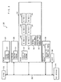
- ROM 120 there are stored a diagnosing program 122 and an editing program 123, such as a sequence program as described later, as well as a system program 121 for controlling the CNC apparatus.
- the RAM 130 is provided with a register 131 for storing addresses of storing means for storing the sequence programs to be executed for diagnosing and editing, a register 132 for storing addresses of various tables, an area 133 for storing data to be displayed on a CRT screen of the CRT/MDI unit 20, an area 134 for storing the sequence program for use in editing, and a DI table F 135 for storing output signals from the first PC circuit 200 and a DO table G 136 for storing input signals from the first PC circuit, both serving as signal transmitting/receiving means for transmitting and receiving interface signals between the first PC circuit 200 and the CNC circuit 100.
- the non-volatile memory 140 stores therein not only an NC program 141 inputted thereto but also data corresponding to various parameters 142 which have been set along with the NC program.
- the ROM 220 stores therein a system program 221 for a processor 210 of the first PC circuit
- the EEPROM 230 stores therein a sequence program 231 which is to be executed by the first PC circuit 200.
- the processor 10 reads the sequence program 231 from the EEPROM 230 and stores it into the RAM 240 and sequentially executes the executing sequence program 241 stored in the RAM 240.
- the RAM 240 is provided with a DI table F 242 for storing signals outputted from the CNC circuit 100 and inputted to the first PC circuit 200 and a DO table G 243 for storing output signals outputted from the first PC circuit 200 to the CNC circuit 100, both serving as signal transmitting/receiving means for transmitting and receiving interface signals between the first PC circuit and the CNC circuit 100.
- the RAM 240 is further provided with an internal relay table 244 for storing the state of internal relays in the sequence program, a holding type memory table 245 for storing the state of holding type memories such as a variable timer, a counter, a keep relay, or the like, and a DI table X 246 for storing an input signal from the machine tool and a DO table Y 247 for storing an output signal from the first PC circuit 200 to the machine tool 60, both serving as the tables for storing interface signals between the first PC circuit 200 and the machine tool.
- an internal relay table 244 for storing the state of internal relays in the sequence program
- a holding type memory table 245 for storing the state of holding type memories such as a variable timer, a counter, a keep relay, or the like
- DI table X 246 for storing an input signal from the machine tool
- DO table Y 247 for storing an output signal from the first PC circuit 200 to the machine tool 60, both serving as the tables for storing interface signals between the first PC circuit 200 and
- the RAM 240 is provided with a DI table x 248 for storing input signals from the second PC circuit 300 and a DO table y 249 for storing output signals from the first PC circuit 200 to the second PC circuit 300, both serving as signal transmitting/receiving means for transmitting and receiving the interface signals between the first PC circuit 200 and the second PC circuit 300.
- the construction of the first PC circuit 200 differs from that of the PC circuit of the conventional CNC apparatus 10 only in that the RAM 240 is provided with the DI table x 248 for storing the input signals from the second PC circuit 300 and the DO table y 249 for storing the output signals from the first PC circuit 200 to the second PC circuit 300 so as to permit transmission and reception of the interface signals between the first and the second PC circuit.
- the ROM 320 stores therein a system program 321 for a processor 310 of the second PC circuit 300.
- the EEPROM 330 stores therein a sequence program 331 according to which the second PC circuit 300 controls the peripheral device 80.
- the processor 310 executes the sequence program 331, this program is read into the RAM 340, and the sequence program 341 thus read in is executed.
- the RAM 340 is provided with a DI table X 342 for storing input signals from the peripheral device 80 and a DO table Y 343 for storing output signals outputted from the second PC circuit 300 to the peripheral device 80, both serving as the tables for storing interface signals between the second PC circuit 300 and the peripheral device 80.
- the RAM 340 is further provided with a table 344 for storing the contents of the internal relays in the sequence program 341 and a table 345 for storing type memory table 245 for storing the state of holding type memories.
- the RAM 340 is further provided with a DI table x 346 for storing signals inputted from the first PC circuit 200 and a DO table y 347 for storing signal outputted from the second PC circuit 300 to the first PC circuit 200, both serving as signal transmitting/receiving means for transmitting and receiving interface signals between the second PC circuit 300 and the first PC circuit 200.
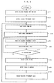
- the processor 210 reads the sequence program 231 stored in the EEPROM 230 and writes it into the execution sequence program (241) area of the RAM 240 (step a1), and then writes the data 251 of the holding type memory table image of the non-volatile memory 250 into the holding type memory table 245 of the RAM 240 to thereby restore the states of the variable timer, counter, keep relay, etc. to their original states (step a2).
- the processor 210 takes in the output signal that is outputted from the CNC circuit 100 to the first PC circuit 200. That is, the processor 210 copies the state of the DI table F 135 of the RAM 130 of the CNC circuit 100 into the DI table F 242 of the RAM 240 (step a3). Further, the processor 210 reads the state of the input signal of the I/O unit 50 from the inputting/outputting circuit 260 and writes it into the DI table X 246 of the RAM 240 (step a4).
- the processor 210 reads an initial step of the sequence program 241 stored in the RAM 240, executes thus-read 1-step sequence program according to the data of the DI table F 242, DI table X 246, DI table x 248, internal relay table 244 and holding type memory table 245, and writes the results of the execution into the DO table G 243, DO table Y 247, DO table y 249, internal relay table 244 and holding type memory table 245 (steps a5 and a6).
- the processor 210 executes one step of the read sequence program according to the signal (DI table F 242) inputted from the CNC circuit 100, the signal (DI table X 246) inputted from the machine tool and the signal (DI table x 248) inputted from the second PC circuit 300.
- the processor 210 writes the corresponding executed result into the DO table G 243 if it is necessary to modify the signal that is to be outputted to the CNC circuit 100; writes the corresponding executed result into the DO table Y 247 if it is necessary to modify the signal that is to be outputted to the machine tool 60; writes the corresponding executed result into the DO table y 249 if it is necessary to modify the signal that is to be outputted to the second PC circuit 300; and, writes the corresponding executed results into the tables 244 and 245, respectively if it is necessary to modify the state of the internal relay and the state of the holding type memory.
- step a7 it is determined whether or not the instruction of one step of the sequence program which was read and analyzed in step a5 is an instruction for ending one sequence (step a7). If it is not an instruction for the end, the processing returns to step a5, whereby the processings from step a5 to step a7 are repeatedly executed until an instruction for ending one-sequence operation is read out.
- the processor 210 copies the contents of the DO table G 243 in the RAM 240 of the first PC circuit 200 into the DO table G 136 of the RAM 130 of the CNC circuit 100 (step a8), and simultaneously copies the state of the DO table Y 247 into the inputting/outputting circuit 260 to thereby make the state of the output signal of the I/O unit 50 as same as the state for being stored in the table Y 247 (step a9). Further, the processor 210 copies the content of the holding type memory table 245 of the RAM 240 into the holding type memory table image area (251) of the non-volatile memory 250 to thereby back up the contents of the holding type memory (step a10). Then, the processing operation returns to step a3, whereby the above-mentioned step a3 and succeeding steps of the processing are repeatedly executed.
- the state of the output signal from the first PC circuit 200 is stored in the DO table G 136 of the RAM 130 of the CNC circuit 100, so that the processor 110 of the CNC circuit 100 distribute commands among respective shafts of the machine tool 60, etc. for their numerical control according to the data of this DO table G 136 and the NC program. Also, the processor 110 writes the command to the first PC circuit 200 into the DI table F 135. Further, in step a9, a command for machine tool control is issued from the first PC circuit 200 to control the machine tool 60, thereby performing machining of a work.
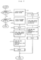
- the processor 310 reads the sequence program 331 stored in the EEPROM 330 and writes it into the execution sequence program (341) area of the RAM 340 (step b1), and writes the data of the holding memory table image 351 of the non-volatile memory 350 into the holding memory table 345 of the RAM 340 to thereby restore the variable timer, counter, keep relay, etc. to their respective original state (step b2).
- the processor 310 reads in the signals that are outputted from the first PC circuit 200 to the second PC circuit 300. That is, the processor 310 copies the state of the DO table y 249 of the RAM 240 of the first PC circuit 200 into the DI table x 346 of the RAM 340 (step b3) and also reads the state of the input signals of the I/O unit 70 from the inputting/outputting circuit 360 and writes it into the DI table X 342 of the RAM 340 (step b4).
- the processor 310 reads an initial step of the sequence program 341 stored in the RAM 340 and executes the thus-read 1-step sequence program according to the data of the DI table X 342, DI table x 346, internal relay table 344 and holding type memory table 345 and writes the results of execution into the DO table Y 343, DO table y 347, internal relay table 344 and holding type memory table 345 (steps b5 and b6).
- the processor 310 executes one step of the read sequence program according to the signal (DI table x 346) inputted from the first PC circuit 200 and the signal (DI table X 342) inputted from the peripheral device.
- the processor 310 writes the corresponding executed result into the DO table Y 343 if it is necessary to modify the output signal to the peripheral device 80; writes the corresponding executed result into the DO table y 347 if it is necessary to modify the output signal to the first PC circuit 200; and, writes the corresponding executed results into the tables 344 and 345, respectively if it is necessary to modify the state of the internal relay and the state of the holding type memory.
- step b7 it is determined whether or not the instruction of the one step of the sequence program which was read and analyzed in step b5 is an instruction for ending the one sequence operation (step b7). If it is not an instruction for ending, the processing operation returns to step b5, whereby the processings from step b5 to step b7 are repeatedly executed until an instruction for ending, the one-sequence operation is read out.
- the processor 310 copies the contents of the DO table y 347 in the RAM 340 of the second PC circuit 300 into the DI table x 248 of the RAM 240 of the first PC circuit 200 (step b8) and simultaneously copies the state of the DO table Y 343 into the inputting/outputting circuit 360 to thereby make the state of the output signal of the I/O unit 70 as same as the state for being stored in the table y 347 (step b9). Further, the processor 310 copies the contents of the holding type memory table 345 of the RAM 340 into the holding type memory table image area (351) of the non-volatile memory 350 to thereby back up the contents of the holding type memory 345 (step b10). Then, the processing operation returns to step b3 to repeat the above-mentioned step b3 and succeeding steps.
- step b9 a command is issued from the second PC circuit 300 to the peripheral circuit 80, whereby the peripheral device 80 is sequence-controlled.
- the CNC circuit 100 and the first PC circuit 200 that is, between the tables F 135 and G 136 of the CNC circuit 100 and the tables F 242 and G 243 of the first PC circuit 200
- signals are transmitted and received, whereby the CNC circuit 100 and the first PC circuit 200 are coordinated to control the machine tool 60.
- the first PC circuit 200 and the second PC circuit 300 that is, between the tables x 248 and y 249 of the first PC circuit and the tables x 346 and y 347 of the second PC circuit 300
- signals are transmitted and received, whereby the first PC circuit 200 and the second PC circuit 300 coordinately drive and control the machine tool 60 and the peripheral device 80.
- the CNC circuit 100, first PC circuit 200 and second PC circuit 300 coordinately and cooperatively drive and control the machine tool 60 and the peripheral device 80.
- the processor 110 of the CNC circuit 100 periodically determines whether a diagnosis command is inputted or an editing command is inputted (step c1 and step c2).
- an editing command is inputted by means of, for example, an editing command key
- the processing operation is switched to an editing mode, and the processor 110 first displays so as for an operator to select which one of the sequence program for the first PC circuit 200 or the sequence program for the second PC circuit 300 is to be edited.
- the processor 110 stores the global addresses of the EEPROM (230 or 330) of the PC circuit, in which the selected sequence program is stored into the sequence program address register 131 in the RAM 130 and also stores the addresses of the respective tables of the RAM (240 or 340) of the PC circuit which executes the selected sequence program into the table address register 132.
- the global addresses of the EEPROM 230 are written into the sequence program address register 131, and the respective foremost addresses of the DI tables F 242, X 246, and x 248, DO tables G 243, Y 247, and y 249, internal relay table 244 and holding type memory table 245 are written into the table address register 132.
- the sequence program of the second PC circuit 300 is selected, the global addresses of the EEPROM 330 are written into the sequence program address register 131, and the respective foremost addresses of the DI tables X 342 and x 346, DO tables Y 343 and y 347, internal relay table 344 and holding type memory table 345 are written into the table address register 132 (steps c10 and c11). Then, the editing program 123 stored in the ROM 120 is executed (step c12).
- the processor 110 displays inputting menu on the CRT screen of the CRT/MDI unit 20 and waits until one of inputting menu, outputting menu and editing menu is selected (steps d1 to d4).
- the sequence program stored in the memory card 30 is inputted, via the memory card interface 180, to the sequence program memory (EEPROM 230 or 330) corresponding to the global address stored in the sequence program address register 131, thereby ending the inputting processing (step d5).
- step d3 When the outputting menu is selected (step d3) instead of the inputting menu, the sequence program stored in the sequence program memory (EEPROM 230 or 330) corresponding to the global address indicated by the sequence program address register 131 is outputted, via the memory card interface 180, to the memory card 30, thereby ending the outputting processing (step d6).
- the processor 110 when the editing menu is selected (step d4), the processor 110 writes the sequence program stored in the sequence program memory (EEPROM 230 or 330) designated by the global address stored in the sequence program address register 131 into the editing sequence program area 134 of the RAM 130, and, according to the editing operation, sequentially displays onto the CRT screen the sequence program stored in the editing sequence program area 134 and alters the sequence program to thereby permit the program editing to be executed until a command to end the editing is inputted (steps d7 to d9).
- the processor 110 Upon completion of the editing operation, the processor 110 stores the edited sequence program stored in the editing sequence program area 134 into the sequence program memory designated by the sequence program address register 131 (step d10), thereby ending the edit processing.
- sequence program for use in the first PC circuit or the sequence program for use in the second PC circuit can be individually stored into the memory (EEPROM 230 or 330) and can be individually outputted, for example, to the memory card 30 and the like and further can be individually edited, it does not happen that when modifying one of the sequence programs, the other thereof is altered erroneously, with the result that the safety is ensured.
- step c1 when a command for diagnosis is inputted (step c1), as in the case of the above-mentioned step c8, display is made for requiring an operator to select either sequence program for the first PC circuit 200 or sequence program for the second PC circuit 300.
- the processor 110 stores the global addresses of the EEPROM (230 or 330) of the PC circuit, in which the selected sequence program is stored, into the sequence program address register 131 in the RAM 130, and also stores the addresses of the respective tables of the RAM (240 or 340) of the PC circuit which executes the selected program into the table address register 132 of the RAM 130 (step c3 to c6).
- the processor 110 executes the diagnosing program 122 stored in the ROM 120 (step c7).
- This diagnosing program 122 is executed according to the processing of Fig. 9.
- the sequence program stored in the sequence program memory (EEPROM 230 or 330) designated by the global address stored in the sequence program address register 131 is read out by an amount corresponding to one page (one full-screen page) capable of being displayed on the CRT screen and stores this sequence program into a monitor display data memory area by converting it to graphic display data (ladder diagram) (step e1).
- the processor 110 decodes the thus-read sequence program and determines the respective operand addresses (step e2).
- the processor 110 reads out the states of the signals of the respective operand addresses from the respective tables designated by the table address register 132 and stores them into the monitor display data memory area of the RAM 130, thereby displaying the operational state of the sequence program graphically (by way of a ladder diagram) on the CRT screen (steps e3 and e4).
- the processor 110 determines whether a command for feeding a page is inputted or a command for ending the monitoring is inputted (steps e5 and e6).
- a command for feeding a page is issued, the processing operation returns to step e1, and the next one-page sequence program is read out to execute the above-mentioned processings.
- the operational state of the selected sequence program (for use in the first PC circuit or for use in the second PC circuit) is sequentially displayed on the CRT screen in the form of a graphic diagram (ladder diagram), so that it is possible to diagnose the sequence program by studying such display.
- the EEPROMs one storing a sequence program for PC circuit, and the other storing a sequence program for the second PC circuit
- it may be arranged without providing the EEPROMs respectively that the sequence program for use in the first PC circuit and that for use in the second PC circuit are separately stored in one EEPROM.
- the second PC circuit for the sequence control of the peripheral device is additionally provided in addition to the first PC circuit for the control of the main body of a machine (machine tool).
- the processor of the first PC circuit for controlling the main body of the machine may also be used for the sequence control of the peripheral device.
- the sequence program (the sequence program for the first PC circuit) for controlling the main body of the machine and the sequence program (the sequence program for the second PC circuit) for controlling the peripheral devices may be stored in separate memories, maintaining the independence from each other.
Abstract
Description
Claims (6)
- A numerical control apparatus, comprising storing means for storing a sequence program for performing sequence control of a machine to be numerical controlled and a sequence program for performing sequence control of a peripheral device which operates coordinating with the operation of the machine,
wherein the machine is sequence controlled and numerical controlled and the peripheral device is sequence controlled coordinating with the operation of the machine. - A numerical control apparatus, comprising:memory means for storing a plurality of sequence programs;program executing means for executing respective sequence programs;selecting means for selecting one of the plurality of sequence programs;diagnosing means for displaying the content and executed state of the selected sequence program; andediting means for performing editing, inputting and outputting of the selected sequence program.
- A numerical control apparatus, comprising:storing means for storing a sequence program for performing sequence control of a machine to be numerical controlled and a sequence program for performing sequence control of a peripheral device which operates coordinating with the operation of the machine;program executing means for executing respective sequence programs;signal transmitting and receiving means for transmitting and receiving interface signal between a numerical control section and the program executing means, designed to coordinate the numerical control of the machine with the execution of the sequence program for performing sequence control of the machine;signal transmitting and receiving means, for transmitting and receiving interface signal, designed to coordinate the execution of the sequence program for performing sequence control of the machine with the execution of the sequence program for performing sequence control of the peripheral device;selecting means for selecting one of the sequence programs;diagnosing means for displaying the content and executed state of the selected sequence program; andediting means for performing editing, inputting and outputting of the selected sequence program.
- A numerical control apparatus according to claim 3, wherein each of said signal transmitting and receiving means is equipped with storing means for storing output signal from one to the other and an input signal from said the other to said one.
- A numerical control apparatus, comprising:a numerical control circuit;a first programmable controller circuit for performing sequence control of a machine to be numerical controlled; anda second programmable controller circuit for performing sequence control of a peripheral device,
wherein each of the first and the second programmable controller circuit has a CPU and memories in storing sequence programs executed under the control of the CPU; and furthersignal transmitting and receiving means for performing signal transmission and reception under the control of the CPU are provided between the numerical control circuit and the first programmable controller circuit and between the first programmable controller circuit and the second programmable controller circuit, respectively. - A numerical control apparatus according to claim 5, wherein the numerical control circuitis equipped with interfaces to a manual inputting device with a display screen and for connection to an external memory device; and,has a memory area for storing a program for editing and/or diagnosing the sequence programs, andthe manual inputting device with a display screen connected to the numerical control circuit can be switched toa selecting mode for selecting either the sequence program to be edited and/or diagnosed, which is stored in the memory of the first programmable controller circuit, or one stored in the memory of the second programmable controller circuit,an inputting mode for storing the program stored in a storage medium of the external memory device into the memory of the first or the second programmable controller circuit selected according to the selecting mode,an outputting mode for storing the program stored in the memory of the first or the second programmable controller circuit selected according to the selecting mode into the storage medium of the external memory device,an editing mode for editing the program by the use of the display screen and storing the edited program into the memory of the first or the second programmable controller circuit selected according to the selecting mode, anda diagnosing mode for displaying the program stored in the memory of the first or the second programmable controller circuit selected according to the selecting mode onto the display screen in a form wherein an operator can understand the program.
Applications Claiming Priority (4)
| Application Number | Priority Date | Filing Date | Title |
|---|---|---|---|
| JP17545796 | 1996-06-17 | ||
| JP8175457A JPH103307A (en) | 1996-06-17 | 1996-06-17 | Numerical controller |
| JP175457/96 | 1996-06-17 | ||
| PCT/JP1997/002081 WO1997049012A1 (en) | 1996-06-17 | 1997-06-17 | Numerical controller |
Publications (3)
| Publication Number | Publication Date |
|---|---|
| EP0845721A1 true EP0845721A1 (en) | 1998-06-03 |
| EP0845721A4 EP0845721A4 (en) | 2000-04-19 |
| EP0845721B1 EP0845721B1 (en) | 2004-02-18 |
Family
ID=15996410
Family Applications (1)
| Application Number | Title | Priority Date | Filing Date |
|---|---|---|---|
| EP97926268A Expired - Lifetime EP0845721B1 (en) | 1996-06-17 | 1997-06-17 | Numerical controller |
Country Status (5)
| Country | Link |
|---|---|
| US (1) | US5986425A (en) |
| EP (1) | EP0845721B1 (en) |
| JP (1) | JPH103307A (en) |
| DE (1) | DE69727646T2 (en) |
| WO (1) | WO1997049012A1 (en) |
Cited By (3)
| Publication number | Priority date | Publication date | Assignee | Title |
|---|---|---|---|---|
| EP1450226A2 (en) * | 2003-02-21 | 2004-08-25 | Fanuc Ltd | Numerical controller |
| EP1505462A2 (en) * | 2003-08-05 | 2005-02-09 | Fanuc Ltd | Programmable controller |
| EP1517204A2 (en) * | 2003-09-05 | 2005-03-23 | Fanuc Ltd | Programmable controller |
Families Citing this family (11)
| Publication number | Priority date | Publication date | Assignee | Title |
|---|---|---|---|---|
| DE10149147A1 (en) * | 2001-10-04 | 2003-04-17 | Heidenhain Gmbh Dr Johannes | Method and device for creating or changing NC programs |
| JP3896076B2 (en) * | 2002-12-26 | 2007-03-22 | ファナック株式会社 | Numerical controller |
| JP2011096114A (en) * | 2009-10-30 | 2011-05-12 | Brother Industries Ltd | Numerical control device, method of controlling machine tool, and control program of the machine tool |
| DE102010010014B3 (en) * | 2010-03-03 | 2011-04-21 | Sick Ag | Safety device with a configurable safety controller |
| JP2014035564A (en) * | 2012-08-07 | 2014-02-24 | Fanuc Ltd | Numerical value control device having multi-core processor |
| JP5628954B2 (en) * | 2013-03-29 | 2014-11-19 | ファナック株式会社 | Motor control device for synchronously controlling a plurality of motors |
| US9891617B2 (en) | 2014-01-22 | 2018-02-13 | Omax Corporation | Generating optimized tool paths and machine commands for beam cutting tools |
| US10859997B1 (en) | 2017-12-04 | 2020-12-08 | Omax Corporation | Numerically controlled machining |
| US11554461B1 (en) | 2018-02-13 | 2023-01-17 | Omax Corporation | Articulating apparatus of a waterjet system and related technology |
| JP6829221B2 (en) * | 2018-04-13 | 2021-02-10 | ファナック株式会社 | Numerical control system |
| JP6787951B2 (en) | 2018-06-05 | 2020-11-18 | ファナック株式会社 | Numerical control device |
Citations (6)
| Publication number | Priority date | Publication date | Assignee | Title |
|---|---|---|---|---|
| US4931709A (en) * | 1986-04-07 | 1990-06-05 | Fanuc Ltd. | NC unit processing method |
| US5115177A (en) * | 1988-08-26 | 1992-05-19 | Fanuc Ltd. | Malfunction diagnosis method |
| WO1993004414A1 (en) * | 1991-08-19 | 1993-03-04 | Fanuc Ltd | Numerical control device |
| US5317501A (en) * | 1987-10-13 | 1994-05-31 | Bernhard Hilpert | Control system for a numerically controlled machine |
| US5471380A (en) * | 1993-03-31 | 1995-11-28 | Mitsubishi Denki Kabushiki Kaisha | Programmable controller and methods of setting and displaying its internal information |
| EP0401376B1 (en) * | 1988-09-02 | 1996-03-13 | Fanuc Ltd. | System for diagnosing cnc |
Family Cites Families (15)
| Publication number | Priority date | Publication date | Assignee | Title |
|---|---|---|---|---|
| US4396984A (en) * | 1981-03-06 | 1983-08-02 | International Business Machines Corporation | Peripheral systems employing multipathing, path and access grouping |
| CA1216343A (en) * | 1983-05-02 | 1987-01-06 | Tomohiro Murata | Method and apparatus for controlling an operation sequence of a machinery |
| JP2685071B2 (en) * | 1986-03-10 | 1997-12-03 | 三菱電機株式会社 | Numerical control unit |
| JPS6388609A (en) * | 1986-10-01 | 1988-04-19 | Mitsubishi Electric Corp | Sequence program monitoring method for sequence controller |
| JPS63289605A (en) * | 1987-05-21 | 1988-11-28 | Fanuc Ltd | Sequence control monitor system |
| JPS647204A (en) * | 1987-06-30 | 1989-01-11 | Fanuc Ltd | Preparation of nc data for rough working |
| JPH0692057B2 (en) * | 1987-08-25 | 1994-11-16 | 豊田工機株式会社 | Numerical control machine tool |
| JPH0172605U (en) * | 1987-11-02 | 1989-05-16 | ||
| JPH02148109A (en) * | 1988-11-29 | 1990-06-07 | Fanuc Ltd | Cnc control system |
| JPH03189704A (en) * | 1989-12-19 | 1991-08-19 | Fanuc Ltd | Numerical control system |
| JPH0772789A (en) * | 1993-09-02 | 1995-03-17 | Matsushita Electric Ind Co Ltd | Method and device for sequence control over automatic machine, and information medium for the same |
| JPH07200019A (en) * | 1993-12-28 | 1995-08-04 | Ricoh Co Ltd | Robot controller |
| JP3619539B2 (en) * | 1994-06-14 | 2005-02-09 | ファナック株式会社 | Tool path editing method |
| JPH0854917A (en) * | 1994-08-12 | 1996-02-27 | Fanuc Ltd | Relief height deciding method for curved surface machining |
| JP3460747B2 (en) * | 1995-04-12 | 2003-10-27 | 三菱電機株式会社 | Numerical control unit |
-
1996
- 1996-06-17 JP JP8175457A patent/JPH103307A/en active Pending
-
1997
- 1997-06-17 DE DE69727646T patent/DE69727646T2/en not_active Expired - Fee Related
- 1997-06-17 EP EP97926268A patent/EP0845721B1/en not_active Expired - Lifetime
- 1997-06-17 US US09/011,705 patent/US5986425A/en not_active Expired - Fee Related
- 1997-06-17 WO PCT/JP1997/002081 patent/WO1997049012A1/en active IP Right Grant
Patent Citations (6)
| Publication number | Priority date | Publication date | Assignee | Title |
|---|---|---|---|---|
| US4931709A (en) * | 1986-04-07 | 1990-06-05 | Fanuc Ltd. | NC unit processing method |
| US5317501A (en) * | 1987-10-13 | 1994-05-31 | Bernhard Hilpert | Control system for a numerically controlled machine |
| US5115177A (en) * | 1988-08-26 | 1992-05-19 | Fanuc Ltd. | Malfunction diagnosis method |
| EP0401376B1 (en) * | 1988-09-02 | 1996-03-13 | Fanuc Ltd. | System for diagnosing cnc |
| WO1993004414A1 (en) * | 1991-08-19 | 1993-03-04 | Fanuc Ltd | Numerical control device |
| US5471380A (en) * | 1993-03-31 | 1995-11-28 | Mitsubishi Denki Kabushiki Kaisha | Programmable controller and methods of setting and displaying its internal information |
Non-Patent Citations (2)
| Title |
|---|
| PATENT ABSTRACTS OF JAPAN vol. 1995, no. 11, 26 December 1995 (1995-12-26) & JP 07 200019 A (RICOH CO LTD), 4 August 1995 (1995-08-04) * |
| See also references of WO9749012A1 * |
Cited By (6)
| Publication number | Priority date | Publication date | Assignee | Title |
|---|---|---|---|---|
| EP1450226A2 (en) * | 2003-02-21 | 2004-08-25 | Fanuc Ltd | Numerical controller |
| EP1450226A3 (en) * | 2003-02-21 | 2006-05-03 | Fanuc Ltd | Numerical controller |
| EP1505462A2 (en) * | 2003-08-05 | 2005-02-09 | Fanuc Ltd | Programmable controller |
| EP1505462A3 (en) * | 2003-08-05 | 2006-05-17 | Fanuc Ltd | Programmable controller |
| EP1517204A2 (en) * | 2003-09-05 | 2005-03-23 | Fanuc Ltd | Programmable controller |
| EP1517204A3 (en) * | 2003-09-05 | 2006-05-10 | Fanuc Ltd | Programmable controller |
Also Published As
| Publication number | Publication date |
|---|---|
| DE69727646D1 (en) | 2004-03-25 |
| US5986425A (en) | 1999-11-16 |
| JPH103307A (en) | 1998-01-06 |
| EP0845721A4 (en) | 2000-04-19 |
| EP0845721B1 (en) | 2004-02-18 |
| DE69727646T2 (en) | 2004-08-05 |
| WO1997049012A1 (en) | 1997-12-24 |
Similar Documents
| Publication | Publication Date | Title |
|---|---|---|
| EP0845721B1 (en) | Numerical controller | |
| US6334076B1 (en) | Method of and apparatus for automatically generating control programs for computer controlled systems | |
| US5406473A (en) | Programmable controller | |
| US5315523A (en) | Numerical control apparatus having a work simulation function | |
| US5327350A (en) | Interactive type numerical control apparatus and method thereof | |
| US4994957A (en) | System for simultaneously displaying all ladder diagram segments in which an operator designated relay appears as an input or output | |
| JPH08123515A (en) | Display system for sequence program | |
| US20050143854A1 (en) | Numerical control device and method | |
| US6711448B2 (en) | Setting display apparatus for a programmable controller | |
| EP0287663B1 (en) | Method and apparatus for numerical control having an override playback function | |
| EP0092312B1 (en) | Method and apparatus for displaying ladder diagrams | |
| US5323308A (en) | Programmable control system | |
| EP1455252A2 (en) | Processing program creation apparatus | |
| EP0942343A2 (en) | Numerical control device | |
| JPS5934549A (en) | Controller for copying machine | |
| JP2880330B2 (en) | Programming device for programmable controller | |
| EP0089194B1 (en) | Method and apparatus for displaying ladder diagrams | |
| CN101308378A (en) | Numerical controller with function to add display screens | |
| JPH04252307A (en) | Interactive numerical controller | |
| JP4275981B2 (en) | Axis feed control device for machine tools | |
| JPH0443281B2 (en) | ||
| JPH07210232A (en) | Numerical controller | |
| JPH10105226A (en) | Programmable display device | |
| JPH07248813A (en) | Numerical controller | |
| JPH07234714A (en) | Numerical controller |
Legal Events
| Date | Code | Title | Description |
|---|---|---|---|
| PUAI | Public reference made under article 153(3) epc to a published international application that has entered the european phase |
Free format text: ORIGINAL CODE: 0009012 |
|
| 17P | Request for examination filed |
Effective date: 19980310 |
|
| AK | Designated contracting states |
Kind code of ref document: A1 Designated state(s): DE |
|
| A4 | Supplementary search report drawn up and despatched |
Effective date: 20000308 |
|
| AK | Designated contracting states |
Kind code of ref document: A4 Designated state(s): DE |
|
| RIC1 | Information provided on ipc code assigned before grant |
Free format text: 7G 05B 19/18 A, 7G 05B 19/414 B |
|
| 17Q | First examination report despatched |
Effective date: 20021025 |
|
| GRAH | Despatch of communication of intention to grant a patent |
Free format text: ORIGINAL CODE: EPIDOS IGRA |
|
| GRAS | Grant fee paid |
Free format text: ORIGINAL CODE: EPIDOSNIGR3 |
|
| GRAA | (expected) grant |
Free format text: ORIGINAL CODE: 0009210 |
|
| AK | Designated contracting states |
Kind code of ref document: B1 Designated state(s): DE |
|
| REF | Corresponds to: |
Ref document number: 69727646 Country of ref document: DE Date of ref document: 20040325 Kind code of ref document: P |
|
| RAP2 | Party data changed (patent owner data changed or rights of a patent transferred) |
Owner name: FANUC LTD |
|
| PLBE | No opposition filed within time limit |
Free format text: ORIGINAL CODE: 0009261 |
|
| STAA | Information on the status of an ep patent application or granted ep patent |
Free format text: STATUS: NO OPPOSITION FILED WITHIN TIME LIMIT |
|
| 26N | No opposition filed |
Effective date: 20041119 |
|
| PGFP | Annual fee paid to national office [announced via postgrant information from national office to epo] |
Ref country code: DE Payment date: 20080626 Year of fee payment: 12 |
|
| PG25 | Lapsed in a contracting state [announced via postgrant information from national office to epo] |
Ref country code: DE Free format text: LAPSE BECAUSE OF NON-PAYMENT OF DUE FEES Effective date: 20100101 |