EP0845403A2 - Servolenksystem für die selbstlenkenden Räder einer oder mehrerer Hinterachsen eines Motorfahrzeuges wie z.B. einem Lastkraftwagen, einem Anhänger und einem Auflieger zum Lenken des Fahrzeuges während der Rückwärtsfahrt - Google Patents
Servolenksystem für die selbstlenkenden Räder einer oder mehrerer Hinterachsen eines Motorfahrzeuges wie z.B. einem Lastkraftwagen, einem Anhänger und einem Auflieger zum Lenken des Fahrzeuges während der Rückwärtsfahrt Download PDFInfo
- Publication number
- EP0845403A2 EP0845403A2 EP97118171A EP97118171A EP0845403A2 EP 0845403 A2 EP0845403 A2 EP 0845403A2 EP 97118171 A EP97118171 A EP 97118171A EP 97118171 A EP97118171 A EP 97118171A EP 0845403 A2 EP0845403 A2 EP 0845403A2
- Authority
- EP
- European Patent Office
- Prior art keywords
- steering
- wheels
- axle
- self
- front axle
- Prior art date
- Legal status (The legal status is an assumption and is not a legal conclusion. Google has not performed a legal analysis and makes no representation as to the accuracy of the status listed.)
- Withdrawn
Links
- 230000005540 biological transmission Effects 0.000 claims description 4
- 238000002485 combustion reaction Methods 0.000 claims description 2
- 230000037431 insertion Effects 0.000 claims 1
- 238000003780 insertion Methods 0.000 claims 1
- 230000000670 limiting effect Effects 0.000 description 3
- 230000004913 activation Effects 0.000 description 1
- 230000006835 compression Effects 0.000 description 1
- 238000007906 compression Methods 0.000 description 1
- 230000000694 effects Effects 0.000 description 1
- 239000007788 liquid Substances 0.000 description 1
- 230000004048 modification Effects 0.000 description 1
- 238000012986 modification Methods 0.000 description 1
- 230000010355 oscillation Effects 0.000 description 1
- 239000013641 positive control Substances 0.000 description 1
- 238000011084 recovery Methods 0.000 description 1
Images

Classifications
-
- B—PERFORMING OPERATIONS; TRANSPORTING
- B62—LAND VEHICLES FOR TRAVELLING OTHERWISE THAN ON RAILS
- B62D—MOTOR VEHICLES; TRAILERS
- B62D13/00—Steering specially adapted for trailers
- B62D13/06—Steering specially adapted for trailers for backing a normally drawn trailer
-
- B—PERFORMING OPERATIONS; TRANSPORTING
- B62—LAND VEHICLES FOR TRAVELLING OTHERWISE THAN ON RAILS
- B62D—MOTOR VEHICLES; TRAILERS
- B62D7/00—Steering linkage; Stub axles or their mountings
- B62D7/06—Steering linkage; Stub axles or their mountings for individually-pivoted wheels, e.g. on king-pins
- B62D7/14—Steering linkage; Stub axles or their mountings for individually-pivoted wheels, e.g. on king-pins the pivotal axes being situated in more than one plane transverse to the longitudinal centre line of the vehicle, e.g. all-wheel steering
- B62D7/142—Steering linkage; Stub axles or their mountings for individually-pivoted wheels, e.g. on king-pins the pivotal axes being situated in more than one plane transverse to the longitudinal centre line of the vehicle, e.g. all-wheel steering specially adapted for particular vehicles, e.g. tractors, carts, earth-moving vehicles, trucks
- B62D7/144—Steering linkage; Stub axles or their mountings for individually-pivoted wheels, e.g. on king-pins the pivotal axes being situated in more than one plane transverse to the longitudinal centre line of the vehicle, e.g. all-wheel steering specially adapted for particular vehicles, e.g. tractors, carts, earth-moving vehicles, trucks for vehicles with more than two axles
Definitions
- the present invention relates to an improvement to a power-assisted steering system for the self-steering wheels of one or more rear axles of a vehicle such as a truck, trailer and semitrailer.
- the invention is meant to be applied in steering during backing maneuvers of the vehicle.
- Vehicles provided with rear axles with self-steering wheels i.e., with wheels which automatically follow the steering of the front wheels along the towing curve, currently cannot perform backing because the rear wheels cannot follow the towing curve. In this case it is necessary to first lock the self-steering rear axle so that the wheels are in the straight travel position.
- the aim of the present invention is to provide a power-assisted steering system which maintains the normal behavior of the self-steering axle when the vehicle travels forward and allows, during backing maneuvers, to steer the rear axle proportionally to the steering of the front axle.
- an object of the present invention is to reduce, during backing maneuvers, the steering radius, improve the maneuverability of the vehicle and reduce tire wear.
- Another object of the present invention is to provide a system which is structurally simple and highly reliable in operation.
- a system for steering, during backing, the self-steering wheels of at least a rear axle of a motor vehicle equipped with power-assisted steering on a front axle characterized in that it comprises a double-action hydraulic actuator which acts on said self-steering rear wheels and is connected to a hydraulic pressure source by a servocontrolled distributor actuated by a traction element of the flexible-cable type, which is connected to the steering system of the front axle so as to direct said rear wheels in the steering direction and by the desired extent in proportion to the steering of the front wheels.
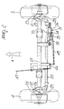
- the reference numerals 1 and 2 designate the two leading wheels of a motor vehicle equipped with power-assisted steering on the front axle and the numerals 3 and 4 designate the rear self-steering wheels, which are arranged behind two respective non-steering wheels 5 and 6.
- the wheels 1, 2 are mounted on an axle 7 and can steer by means of a conventional four-sided linkage composed of two arms 8 and 9 articulately connected to each other by a transverse bar 10.
- a second arm 11 is rigidly coupled to the arm 9 and is connected by means of a traction element 12 to an actuation lever 13 of a hydraulic steering system, which is generally designated by the reference numeral 14 and is capable of causing the oscillation of the lever 13 in one direction or the other when the steering wheel 15 is operated.
- the hydraulic steering system 14 is connected to a delivery 16 of an oil feed pump 17 which is driven by a motor 18 and draws oil from a reservoir 19.
- the oil returns to the reservoir 19 along a return duct 20.
- these wheels are articulated at two pivots 21 and 22 which are shifted forward (i.e., in the travel direction A of the vehicle) with respect to the rotation axis of the wheels 3, 4.
- the wheels 3, 4 have two arms 23, 24 which protrude forward and are articulated by the pivots 21, 22 to two arms 25, 26 which are fixed to the opposite ends of the axle 27 that supports the wheels.
- the arms 23, 24 are rigidly coupled to respective levers 28, 29 which are mutually connected by a bar 30 which forms, together with them, a four-sided linkage system for steering the rear wheels 3, 4 which allows said wheels to self-orientate along the towing curve set by the front wheels.
- a double-action jack 31 provided with a stem 32 articulated to the axle 27 and a cylinder 33 which is articulated to a bar 30; in said cylinder, the piston 34 forms two chambers 35, 36 into which pressurized oil is fed in order to orientate the steered wheels 3, 4 in one direction or the other.
- the pressurized oil for actuating the rear self-steering wheels is supplied by an additional pump 37, which is actuated by an independent motor 38 (of the internal-combustion or electric type), which draws the oil from a reservoir 39 and, by means of a delivery duct 40, sends it to the jack 31.
- a distributor 44 of the two-way, three-position type is arranged between the delivery duct 40 and a return duct 41 which returns the oil to the reservoir 39, in addition to an anticavitation valve 42 and to a pressure limiting valve 43.
- the distributor 44 is installed on the jack 31 and has a slide valve which, by means of an extendable rod 45, is connected to the end of an L-shaped transmission lever 46 which is pivoted to the chassis of the vehicle.
- the opposite end of the transmission lever 46 is connected, by a traction element of the flexible-cable type 47, to the lever 13 of the hydraulic steering system 14.
- An electric valve 48 is interposed between the ducts 40 and 41 and is controlled by a sensor 49; the valve has the purpose of hydraulically disengaging the distributor 44 when the rear wheels 3, 4 must remain self-steering.
- the sensor 49 can be a switch which is operated by the driver of the vehicle or associated with the backing control, so as to move the electric valve 48 into the position wherein the connection between the delivery duct 40 and the return duct 41 is closed and the pressurized oil fed by the pump 37 can actuate the jack 31 in the direction that corresponds to the position assumed by the distributor 44.
- the rod 45 is for example of the type with preloaded springs, such as to make said rod normally rigid but allow extension thereof both under traction and under compression in order to allow the lever 13 to oscillate even if the rear self-steering wheels 3 and 4 are blocked.
- the rotation of the steering wheel 15 causes, by means of the lever 13, the flexible-cable traction element 47 and the extendable rod 45, a movement of the slide valve of the distributor 44 in the direction in which the supply of oil to the jack 31 causes a corresponding steering effect of the rear wheels 3, 4.
- Steering of the rear self-steering wheels is actuated only during the backing of the vehicle, when the sensor 49 activates the electric valve 48 from the normal position, in which it bypasses the distributor 44, to the position in which it makes it possible to use the hydraulic energy of the pump 37, connecting the delivery 40 to the chamber 35 or 36 depending on the shift undergone by the distributor 44.
- Control of the steering of the rear self-steering wheels during backing maneuvers occurs by means of the steering wheel 15, and the steering angle of the rear wheels is proportional to the steering angle of the front wheels, taking into account the leverage ratios which are present in the actuation of the distributor by means of the flexible-cable traction element 47.
- the sensor 49 keeps the electric valve 48 deactivated, so that the delivery 40 of the pump 37 is connected to the return duct 41 in the reservoir 39 and the self-steering rear axle has the natural behavior of a towed rear axle.
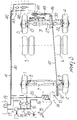
- figure 3 illustrates a solution in which the pressurized liquid for actuating the jack 31 is supplied by the pump 17 through a duct 50 and a flow splitter valve 51, which divides the flow and supplies with a constant flow-rate the hydraulic steering system 14 with the duct 16 and the jack 31 with the duct 40.
- a flow splitter valve 51 which divides the flow and supplies with a constant flow-rate the hydraulic steering system 14 with the duct 16 and the jack 31 with the duct 40.
- the pump 37 can be actuated by the motor itself of the vehicle by means of a suitable transmission.
- a substantial advantage of the invention is constituted by the fact that the flexible-cable traction element, being an inextensible mechanical element, ensures simultaneousness of the position of the front steered wheels and of the rear wheels throughout the steering maneuver.
- the system allows to compensate for the steering angle of the rear wheels that corresponds to the angle set with the front wheels if the rear wheels, for any reason (for example by placing themselves against an obstacle during backing), arrange themselves at a different angle due to a momentary opening of the pressure limiting valve 43 caused by an increase in pressure on the duct 40 above the set value of the valve 43.
Applications Claiming Priority (2)
| Application Number | Priority Date | Filing Date | Title |
|---|---|---|---|
| IT96BO000552A IT1286739B1 (it) | 1996-10-31 | 1996-10-31 | Perfezionamento ad un impianto di sterzatura servoassistita delle ruote autosterzanti di uno o piu' assali posteriori di un veicolo |
| ITBO960552 | 1996-10-31 |
Publications (2)
| Publication Number | Publication Date |
|---|---|
| EP0845403A2 true EP0845403A2 (de) | 1998-06-03 |
| EP0845403A3 EP0845403A3 (de) | 1999-08-25 |
Family
ID=11341685
Family Applications (1)
| Application Number | Title | Priority Date | Filing Date |
|---|---|---|---|
| EP97118171A Withdrawn EP0845403A3 (de) | 1996-10-31 | 1997-10-20 | Servolenksystem für die selbstlenkenden Räder einer oder mehrerer Hinterachsen eines Motorfahrzeuges wie z.B. einem Lastkraftwagen, einem Anhänger und einem Auflieger zum Lenken des Fahrzeuges während der Rückwärtsfahrt |
Country Status (2)
| Country | Link |
|---|---|
| EP (1) | EP0845403A3 (de) |
| IT (1) | IT1286739B1 (de) |
Cited By (8)
| Publication number | Priority date | Publication date | Assignee | Title |
|---|---|---|---|---|
| WO2000007866A1 (en) * | 1998-08-07 | 2000-02-17 | Armando Biondi | Rotating oleodynamic distribution system for the steering of rear axles of vehicles |
| WO2001047764A1 (en) * | 1999-12-23 | 2001-07-05 | New Holland North America, Inc. | Offset kingpin for a rear steering axle on an agricultural combine |
| WO2002022429A1 (en) * | 2000-09-13 | 2002-03-21 | Volvo Lastvagnar Ab | Arrangement and method for operating self-steering wheels |
| WO2002083480A1 (en) * | 2001-04-12 | 2002-10-24 | Mtd Products Inc | Four-wheel steering system |
| CN100445149C (zh) * | 2003-06-28 | 2008-12-24 | 德国曼商用车辆股份公司 | 一种载重汽车或者大客车 |
| WO2010133486A1 (de) * | 2009-05-19 | 2010-11-25 | Saf-Holland Gmbh | Stabilisierungsvorrichtung für nachlauflenkachsen von fahrzeugen |
| US9283986B2 (en) * | 2012-11-27 | 2016-03-15 | Xuzhou Heavy Machinery Co., Ltd. | Follow-up steering control system for multi-axle automobile crane, and multi-axle automobile crane |
| WO2016200311A1 (en) | 2015-06-11 | 2016-12-15 | Scania Cv Ab | A method and a system for steering a vehicle |
Family Cites Families (3)
| Publication number | Priority date | Publication date | Assignee | Title |
|---|---|---|---|---|
| JPS61132471A (ja) * | 1984-11-30 | 1986-06-19 | Hino Motors Ltd | 後二軸型車両に使用されるパワ−・ステアリング・システム |
| DE3836020A1 (de) * | 1988-09-07 | 1990-03-15 | Daimler Benz Ag | Allradlenkung fuer kraftfahrzeuge |
| ES2108856T3 (es) * | 1992-07-03 | 1998-01-01 | Marco Bettini | Un grupo de direccion marcha atras en un eje autodirigido de camiones, camiones articulados y similares. |
-
1996
- 1996-10-31 IT IT96BO000552A patent/IT1286739B1/it active IP Right Grant
-
1997
- 1997-10-20 EP EP97118171A patent/EP0845403A3/de not_active Withdrawn
Cited By (11)
| Publication number | Priority date | Publication date | Assignee | Title |
|---|---|---|---|---|
| WO2000007866A1 (en) * | 1998-08-07 | 2000-02-17 | Armando Biondi | Rotating oleodynamic distribution system for the steering of rear axles of vehicles |
| US6508330B1 (en) | 1998-08-07 | 2003-01-21 | Armando Biondi | Rotating oleodynamic distribution system for the steering of rear axles of vehicles |
| WO2001047764A1 (en) * | 1999-12-23 | 2001-07-05 | New Holland North America, Inc. | Offset kingpin for a rear steering axle on an agricultural combine |
| WO2002022429A1 (en) * | 2000-09-13 | 2002-03-21 | Volvo Lastvagnar Ab | Arrangement and method for operating self-steering wheels |
| US6868935B2 (en) | 2000-09-13 | 2005-03-22 | Volvo Lastvagnar Gb | Arrangement and method for operating self-steering wheels |
| WO2002083480A1 (en) * | 2001-04-12 | 2002-10-24 | Mtd Products Inc | Four-wheel steering system |
| CN100445149C (zh) * | 2003-06-28 | 2008-12-24 | 德国曼商用车辆股份公司 | 一种载重汽车或者大客车 |
| WO2010133486A1 (de) * | 2009-05-19 | 2010-11-25 | Saf-Holland Gmbh | Stabilisierungsvorrichtung für nachlauflenkachsen von fahrzeugen |
| US8628100B2 (en) | 2009-05-19 | 2014-01-14 | Saf-Holland Gmbh | Stabilizing device for steered trailing axles of vehicles |
| US9283986B2 (en) * | 2012-11-27 | 2016-03-15 | Xuzhou Heavy Machinery Co., Ltd. | Follow-up steering control system for multi-axle automobile crane, and multi-axle automobile crane |
| WO2016200311A1 (en) | 2015-06-11 | 2016-12-15 | Scania Cv Ab | A method and a system for steering a vehicle |
Also Published As
| Publication number | Publication date |
|---|---|
| IT1286739B1 (it) | 1998-07-17 |
| ITBO960552A1 (it) | 1998-05-01 |
| ITBO960552A0 (it) | 1996-10-31 |
| EP0845403A3 (de) | 1999-08-25 |
Similar Documents
| Publication | Publication Date | Title |
|---|---|---|
| US4770430A (en) | Self-steering axle assembly for vehicles | |
| US5364113A (en) | Self-steering axle for vehicles | |
| US4441730A (en) | Steering device for many-axled goose-neck trailers | |
| US4603873A (en) | Device for straight traveling stabilization and change of attitude on predetermined paths for vehicle axles | |
| US9004519B1 (en) | Tow bar controlled trailer and method | |
| US4792148A (en) | Semi-trailer truck | |
| US3834480A (en) | Hydraulic trailer steering and sway control mechanism | |
| US4856814A (en) | Adjustable, proportionally steerable auxiliary wheel asemblies for trucks | |
| WO2007128072A1 (en) | Steering system for road transport vehicles | |
| US3880439A (en) | Self steering mechanism | |
| US3618983A (en) | Antijackknifing system | |
| EP0577571B1 (de) | Lenkgruppe zur Rückwärtsfahrt für eine Selbstlenkachse in Lastkraftwagen, Sattelzügen oder dergleichen | |
| US5479999A (en) | Powered, automatic, self-tracking system for the rear axles of trucks, trailers and buses | |
| EP0845403A2 (de) | Servolenksystem für die selbstlenkenden Räder einer oder mehrerer Hinterachsen eines Motorfahrzeuges wie z.B. einem Lastkraftwagen, einem Anhänger und einem Auflieger zum Lenken des Fahrzeuges während der Rückwärtsfahrt | |
| US2650100A (en) | Steerable trailer front wheel mechanism | |
| EP2894069B1 (de) | Lenk- und Bremsanordnung | |
| US4161329A (en) | Tractor to trailer connect system | |
| US2152511A (en) | Hydraulic steering mechanism for road trailers | |
| US4109929A (en) | Anti-jack-knifing apparatus for articulated vehicles | |
| US4394886A (en) | Steering gear with steering-arm lever | |
| EP0786394A1 (de) | Servolenkung für die lenkbaren Räder einer oder mehrerer Hinterachsen eines Lastkraftwagens oder eines Sattelanhängers | |
| EP0710601B1 (de) | Servolenkung für die lenkbaren Räder der Hinterachse eines Fahrzeugs | |
| US3096844A (en) | Steering and follow-up linkage assembly | |
| EP2029415B1 (de) | Lenkbarer anhänger oder sattelanhänger | |
| GB2144087A (en) | Hydraulic steering system for motor vehicles |
Legal Events
| Date | Code | Title | Description |
|---|---|---|---|
| PUAI | Public reference made under article 153(3) epc to a published international application that has entered the european phase |
Free format text: ORIGINAL CODE: 0009012 |
|
| AK | Designated contracting states |
Kind code of ref document: A2 Designated state(s): DE ES FR GB |
|
| AX | Request for extension of the european patent |
Free format text: AL;LT;LV;RO;SI |
|
| PUAL | Search report despatched |
Free format text: ORIGINAL CODE: 0009013 |
|
| AK | Designated contracting states |
Kind code of ref document: A3 Designated state(s): AT BE CH DE DK ES FI FR GB GR IE IT LI LU MC NL PT SE |
|
| AX | Request for extension of the european patent |
Free format text: AL;LT;LV;RO;SI |
|
| 17P | Request for examination filed |
Effective date: 20000126 |
|
| AKX | Designation fees paid |
Free format text: DE ES FR GB |
|
| 17Q | First examination report despatched |
Effective date: 20020529 |
|
| STAA | Information on the status of an ep patent application or granted ep patent |
Free format text: STATUS: THE APPLICATION HAS BEEN WITHDRAWN |
|
| 18W | Application withdrawn |
Effective date: 20030114 |