EP0845287A1 - Process and device for plasma gas treatment - Google Patents
Process and device for plasma gas treatment Download PDFInfo
- Publication number
- EP0845287A1 EP0845287A1 EP97308884A EP97308884A EP0845287A1 EP 0845287 A1 EP0845287 A1 EP 0845287A1 EP 97308884 A EP97308884 A EP 97308884A EP 97308884 A EP97308884 A EP 97308884A EP 0845287 A1 EP0845287 A1 EP 0845287A1
- Authority
- EP
- European Patent Office
- Prior art keywords
- plasma
- reaction chamber
- gaseous medium
- reactant gas
- gas
- Prior art date
- Legal status (The legal status is an assumption and is not a legal conclusion. Google has not performed a legal analysis and makes no representation as to the accuracy of the status listed.)
- Granted
Links
- 238000000034 method Methods 0.000 title claims description 6
- 238000006243 chemical reaction Methods 0.000 claims abstract description 62
- 239000000376 reactant Substances 0.000 claims abstract description 37
- 239000007795 chemical reaction product Substances 0.000 claims abstract description 8
- 239000007789 gas Substances 0.000 claims description 64
- 230000000712 assembly Effects 0.000 claims description 6
- 238000000429 assembly Methods 0.000 claims description 6
- 239000003153 chemical reaction reagent Substances 0.000 claims description 6
- 230000008878 coupling Effects 0.000 claims description 4
- 238000010168 coupling process Methods 0.000 claims description 4
- 238000005859 coupling reaction Methods 0.000 claims description 4
- 239000003344 environmental pollutant Substances 0.000 claims description 4
- 231100000719 pollutant Toxicity 0.000 claims description 4
- 230000005855 radiation Effects 0.000 claims description 3
- 150000001875 compounds Chemical class 0.000 claims 1
- 238000005259 measurement Methods 0.000 claims 1
- 238000012544 monitoring process Methods 0.000 claims 1
- 210000002381 plasma Anatomy 0.000 description 53
- 230000003197 catalytic effect Effects 0.000 description 4
- 238000011144 upstream manufacturing Methods 0.000 description 4
- 230000008901 benefit Effects 0.000 description 3
- 239000003054 catalyst Substances 0.000 description 3
- 230000000694 effects Effects 0.000 description 3
- 239000000463 material Substances 0.000 description 3
- 238000007254 oxidation reaction Methods 0.000 description 3
- 238000006722 reduction reaction Methods 0.000 description 3
- 238000003491 array Methods 0.000 description 2
- 238000000746 purification Methods 0.000 description 2
- 229910001220 stainless steel Inorganic materials 0.000 description 2
- 239000010935 stainless steel Substances 0.000 description 2
- 239000000126 substance Substances 0.000 description 2
- 239000000443 aerosol Substances 0.000 description 1
- QVGXLLKOCUKJST-UHFFFAOYSA-N atomic oxygen Chemical compound [O] QVGXLLKOCUKJST-UHFFFAOYSA-N 0.000 description 1
- 230000015572 biosynthetic process Effects 0.000 description 1
- 239000005388 borosilicate glass Substances 0.000 description 1
- 239000012141 concentrate Substances 0.000 description 1
- 239000002826 coolant Substances 0.000 description 1
- 238000001816 cooling Methods 0.000 description 1
- 238000005260 corrosion Methods 0.000 description 1
- 230000007797 corrosion Effects 0.000 description 1
- 238000010586 diagram Methods 0.000 description 1
- 230000002708 enhancing effect Effects 0.000 description 1
- 239000008246 gaseous mixture Substances 0.000 description 1
- 239000011810 insulating material Substances 0.000 description 1
- 229910052751 metal Inorganic materials 0.000 description 1
- 239000002184 metal Substances 0.000 description 1
- 230000001473 noxious effect Effects 0.000 description 1
- 230000003287 optical effect Effects 0.000 description 1
- 230000003647 oxidation Effects 0.000 description 1
- 239000001301 oxygen Substances 0.000 description 1
- 229910052760 oxygen Inorganic materials 0.000 description 1
- 239000002243 precursor Substances 0.000 description 1
- 239000010453 quartz Substances 0.000 description 1
- VYPSYNLAJGMNEJ-UHFFFAOYSA-N silicon dioxide Inorganic materials O=[Si]=O VYPSYNLAJGMNEJ-UHFFFAOYSA-N 0.000 description 1
- WFKWXMTUELFFGS-UHFFFAOYSA-N tungsten Chemical compound [W] WFKWXMTUELFFGS-UHFFFAOYSA-N 0.000 description 1
- 229910052721 tungsten Inorganic materials 0.000 description 1
- 239000010937 tungsten Substances 0.000 description 1
Images


Classifications
-
- B—PERFORMING OPERATIONS; TRANSPORTING
- B01—PHYSICAL OR CHEMICAL PROCESSES OR APPARATUS IN GENERAL
- B01J—CHEMICAL OR PHYSICAL PROCESSES, e.g. CATALYSIS OR COLLOID CHEMISTRY; THEIR RELEVANT APPARATUS
- B01J19/00—Chemical, physical or physico-chemical processes in general; Their relevant apparatus
- B01J19/08—Processes employing the direct application of electric or wave energy, or particle radiation; Apparatus therefor
- B01J19/12—Processes employing the direct application of electric or wave energy, or particle radiation; Apparatus therefor employing electromagnetic waves
- B01J19/122—Incoherent waves
- B01J19/126—Microwaves
-
- B—PERFORMING OPERATIONS; TRANSPORTING
- B01—PHYSICAL OR CHEMICAL PROCESSES OR APPARATUS IN GENERAL
- B01D—SEPARATION
- B01D53/00—Separation of gases or vapours; Recovering vapours of volatile solvents from gases; Chemical or biological purification of waste gases, e.g. engine exhaust gases, smoke, fumes, flue gases, aerosols
- B01D53/32—Separation of gases or vapours; Recovering vapours of volatile solvents from gases; Chemical or biological purification of waste gases, e.g. engine exhaust gases, smoke, fumes, flue gases, aerosols by electrical effects other than those provided for in group B01D61/00
- B01D53/323—Separation of gases or vapours; Recovering vapours of volatile solvents from gases; Chemical or biological purification of waste gases, e.g. engine exhaust gases, smoke, fumes, flue gases, aerosols by electrical effects other than those provided for in group B01D61/00 by electrostatic effects or by high-voltage electric fields
-
- B—PERFORMING OPERATIONS; TRANSPORTING
- B01—PHYSICAL OR CHEMICAL PROCESSES OR APPARATUS IN GENERAL
- B01J—CHEMICAL OR PHYSICAL PROCESSES, e.g. CATALYSIS OR COLLOID CHEMISTRY; THEIR RELEVANT APPARATUS
- B01J12/00—Chemical processes in general for reacting gaseous media with gaseous media; Apparatus specially adapted therefor
- B01J12/002—Chemical processes in general for reacting gaseous media with gaseous media; Apparatus specially adapted therefor carried out in the plasma state
-
- B—PERFORMING OPERATIONS; TRANSPORTING
- B01—PHYSICAL OR CHEMICAL PROCESSES OR APPARATUS IN GENERAL
- B01J—CHEMICAL OR PHYSICAL PROCESSES, e.g. CATALYSIS OR COLLOID CHEMISTRY; THEIR RELEVANT APPARATUS
- B01J19/00—Chemical, physical or physico-chemical processes in general; Their relevant apparatus
- B01J19/08—Processes employing the direct application of electric or wave energy, or particle radiation; Apparatus therefor
- B01J19/087—Processes employing the direct application of electric or wave energy, or particle radiation; Apparatus therefor employing electric or magnetic energy
- B01J19/088—Processes employing the direct application of electric or wave energy, or particle radiation; Apparatus therefor employing electric or magnetic energy giving rise to electric discharges
-
- H—ELECTRICITY
- H05—ELECTRIC TECHNIQUES NOT OTHERWISE PROVIDED FOR
- H05H—PLASMA TECHNIQUE; PRODUCTION OF ACCELERATED ELECTRICALLY-CHARGED PARTICLES OR OF NEUTRONS; PRODUCTION OR ACCELERATION OF NEUTRAL MOLECULAR OR ATOMIC BEAMS
- H05H1/00—Generating plasma; Handling plasma
- H05H1/24—Generating plasma
- H05H1/46—Generating plasma using applied electromagnetic fields, e.g. high frequency or microwave energy
-
- H—ELECTRICITY
- H05—ELECTRIC TECHNIQUES NOT OTHERWISE PROVIDED FOR
- H05H—PLASMA TECHNIQUE; PRODUCTION OF ACCELERATED ELECTRICALLY-CHARGED PARTICLES OR OF NEUTRONS; PRODUCTION OR ACCELERATION OF NEUTRAL MOLECULAR OR ATOMIC BEAMS
- H05H1/00—Generating plasma; Handling plasma
- H05H1/24—Generating plasma
- H05H1/46—Generating plasma using applied electromagnetic fields, e.g. high frequency or microwave energy
- H05H1/461—Microwave discharges
-
- B—PERFORMING OPERATIONS; TRANSPORTING
- B01—PHYSICAL OR CHEMICAL PROCESSES OR APPARATUS IN GENERAL
- B01J—CHEMICAL OR PHYSICAL PROCESSES, e.g. CATALYSIS OR COLLOID CHEMISTRY; THEIR RELEVANT APPARATUS
- B01J2219/00—Chemical, physical or physico-chemical processes in general; Their relevant apparatus
- B01J2219/08—Processes employing the direct application of electric or wave energy, or particle radiation; Apparatus therefor
- B01J2219/0894—Processes carried out in the presence of a plasma
-
- B—PERFORMING OPERATIONS; TRANSPORTING
- B01—PHYSICAL OR CHEMICAL PROCESSES OR APPARATUS IN GENERAL
- B01J—CHEMICAL OR PHYSICAL PROCESSES, e.g. CATALYSIS OR COLLOID CHEMISTRY; THEIR RELEVANT APPARATUS
- B01J2219/00—Chemical, physical or physico-chemical processes in general; Their relevant apparatus
- B01J2219/08—Processes employing the direct application of electric or wave energy, or particle radiation; Apparatus therefor
- B01J2219/12—Processes employing electromagnetic waves
- B01J2219/1203—Incoherent waves
- B01J2219/1206—Microwaves
- B01J2219/1209—Features relating to the reactor or vessel
- B01J2219/1212—Arrangements of the reactor or the reactors
- B01J2219/1218—Multiple reactors
Definitions
- the present invention relates to the use of a plasma to facilitate a reaction between gaseous substances.
- our patent GB 2 273 027 discloses a microwave plasma generator comprising a chamber, means for establishing a microwave field in the chamber, a pair of conical field-enhancing electrodes in the chamber, means for admitting a gaseous medium to be excited to the plasma state, and an axial hole in one of the electrodes through which the excited gaseous medium can be withdrawn from the chamber.
- a plasma enhanced gas reactor comprising a reaction chamber, means for generating a localised plasma in the reaction chamber, means for causing a flow of a first reactant gas and a second reactant gas to intersect in the vicinity of the plasma and means for extracting reaction products from the reaction chamber.
- means for coupling microwave radiation into the chamber and the means for producing a localised plasma comprises a pair of conical field-enhancing electrodes, each of which has an axial hole in it, through one of which one of the reactant gases is admitted to the chamber and through the other of which reaction products are removed from the reaction chamber.
- the diameter of the axial hole or passage in one electrode conical assembly is greater than that of the other and preferably the electrode conical assembly having the smaller diameter axial passage is frusto-conical in form.
- the axial passages formed in the electrode conical assemblies have at least approximately equal diameters and the upstream electrode conical assembly has a series of regularly spaced radial passages by means of which a proportion of the first reactant gas can be extracted and mixed in the second reactant gas prior to being subjected to the plasma.
- the upstream electrode conical assembly has at least one radial passage by means of which the second reactant gas can be mixed with the first reactant gas immediately prior to being subjected to the plasma.
- the gap between the electrode conical assemblies is adjustable.
- the invention also provides a modular plasma processing apparatus comprising a plurality of plasma reaction chambers as aforesaid, means arranged to feed simultaneously a gaseous medium to be processed to each plasma reaction chamber, means for generating separately a plasma in each plasma reaction chamber, and outlet means for removing the processed gaseous medium from the plasma reaction chamber.
- the means for generating separately the plasma in the plasma reaction chambers comprises a microwave generator coupled directly to an associated plasma reaction chamber, and there is included means for controlling the action of the microwave generators comprising means for determining the partial pressure of a component of the gaseous medium and means for varying the power supplied to the microwave generators as a function of the partial pressure of the component of the gaseous medium.
- the means for varying the power supplied to the microwave generators may be adapted to vary equally the power supplied to each of the microwave power generators or alternatively may be adapted to vary the number of microwave generators to which power is supplied.
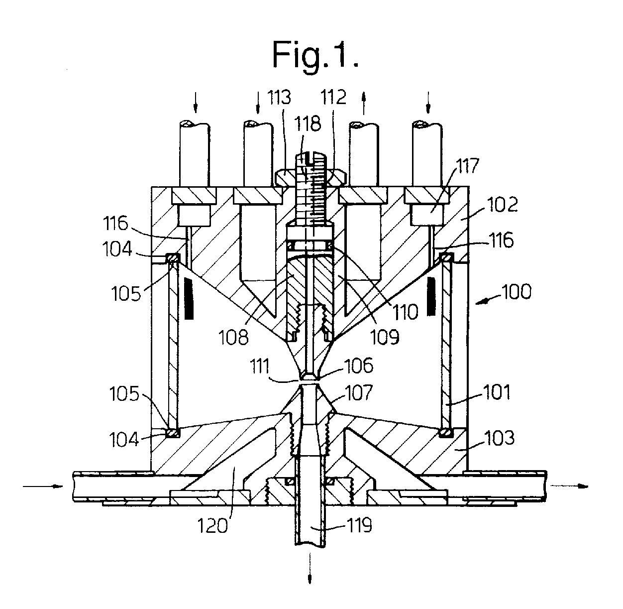
- a plasma reaction chamber 100 consists of a cylinder 101 which is made of an insulating material such as borosilicate glass or quartz and two end-pieces 102 and 103, respectively.
- the cylinder 101 fits into annular grooves 4 which are machined in the end-pieces 102 and 103.
- the cylinder 101 and end-pieces 102 and 103 are sealed by means of O-ring seals 5.
- the assembly is held together by clamps, which are not shown in the figure.
- the end-pieces 102 and 103 are conical in form with the end-piece 102 cone angle smaller than that of the end-piece 103. Screwed into the end pieces 102 and 103 are replaceable electrode tips 106 and 107, respectively.
- the electrode tips 106 and 107 have smaller cone angles than the respective end-pieces 102 and 103 into which they are screwed. Again the electrode tip 106 has a smaller cone angle than that of the electrode tip 107.
- the electrode tip 106 is not screwed directly into the end-piece 102, but is screwed into a cylindrical block 108 which is a sliding fit in a bore 109 in the end-piece 102.
- the block 108 and bore 109 are rendered gas-tight by means of an O-ring seal 110.
- the position of the block 108 in the bore 109 in the end-piece 102, and hence the gap 111 between the electrode tips 106 and 107, can be adjusted by means of a screw 112 and nut 113.
- the electrode tips 106 and 107 each terminate in a sharp annular edge 114.
- the end-piece 102 has a cooling passage 115 formed in it and a number of entry ducts 116 to enable a first reactant gas to be admitted to the reaction chamber 100.
- the entry ducts 116 are fed from a plenum chamber 117 and are so shaped and disposed that the gaseous medium enters the reaction chamber 100 with a swirling motion.
- the end-piece 102, block 108 and electrode tip 106 all have an axial passage in them, by means of which a second reactant gas can be admitted to the chamber 100.
- the end-piece 103 and electrode tip 107 also have an axial passage 119 formed in them, by means of which reaction products can be extracted from the reaction chamber 100.
- the end-piece 103 has a coolant passage 120 formed in it.
- the end-pieces 102 and 103 are made of stainless steel.
- the tips 106 and 107 can be made of the same material or of a more corrosion and heat resistant metal such as tungsten.
- Means are provided for coupling microwave radiation into the reaction chamber 100 from a source, which also is not shown.
- Figure 2(a) illustrates the action of the reaction chamber as described above
- Figures 2(b) and 2(c) illustrate the action of the reaction chamber with different electrode configurations and flow conditions for the two reactant gases.
- both the axial passages 118 and 119 are of the same diameter and the gap 111 between the electrodes 121 is about 2mm.
- a main reactant gas 201 is fed to the inlet of the passage 118 in the end-piece 102 assembly.
- An annular plasma 202 forms in the gap 111 between the electrodes 121.
- a second reactant gas 203 supplied to the reaction chamber 100 via the duct 116 is drawn into the exit passageway 119 in the tip 106 of the end-piece 103 assembly by the venturi effect of the main gas flow across the gap 111 between the electrode-tips 106 and 107 assisted by the swirling flow of the second reactant gas 203.
- the second reactant gas 203 passes through the plasma, facilitating the transfer of energy to it.
- the two gases then react in a zone 204 at the entrance to the passageway 119 in the electrode tip 106 of the end-piece assembly 103.
- the first reactant gas is a gas contaminated with a relatively small proportion, for example (0.1 to 1%), of NO x , which it is desired to remove by reduction with NH containing radicals
- the first reactant gas is passed through the passageway 118, and, although some of it will be excited in the plasma, most of it will bypass the plasma. All of the flow of the precursor for the generation of the NH containing radicals (NH 3 ), on the other hand, passes through the plasma and will be excited, both thermally and electronically, in so doing.
- the main gas contains carbonaceous pollutants which it is desired to remove by oxidation reactions with O containing radicals.
- the second reactant gas can be air or oxygen.
- Figure 2(b) illustrates a different electrode configuration and gas flow pattern.
- the passage 118 in electrode tip 106 of the end piece assembly 102 is smaller in diameter than the passageway 119 in the electrode tip 106 of the end-piece assembly 103.
- the ratio of the diameters of the passages 118 and 119 is dictated by the desired proportions of the two reactant gases.
- the main gas feed 201 is via the entry ducts 116 to the reaction chamber 100, and the second reactant gas 203 is fed to the passage 118 in the end-piece 102 assembly.
- the tip 106 of the end-piece assembly 102 is flat, or even slightly hollowed, to facilitate the entry of the main reactant gas 203 into the gap 111 between the electrode tips 106 and 107.
- an annular plasma 202 is formed with a reaction zone at the entrance to the passage 119 in the electrode tip 107 of the end-piece assembly 103, but in this case, it is the main reactant gas which passes through the plasma and is energised.
- this arrangement requires a higher microwave power input than does the previous arrangement.
- Figure 2(c) shows the same electrode configuration and gas flow pattern as does Figure 2(b), but in this case, the gap 111 between the electrode tips 106 and 107 is increased to about 5mm. As a result, a ball of plasma is formed in the gap 111 between the electrode tips 106 and 107 and both reactant gases are energised simultaneously, and the microwave power requirements are increased further.
- Figure 2(d) shows the same electrode configuration as Figure 2(a) but the upper electrode 106 is surrounded by a shroud 209 through which at least a proportion of the second reagent gas, 203 is fed.
- This arrangement also can be used with the electrode configurations of Figures 2(b) and 2(c).
- Figure 2(e) shows the same electrode configuration as Figure 2(a) but the upper electrode 106 has a number of regularly spaced radial holes 210 immediately upstream of the gap 111 between the electrodes 106 and 107.
- the venturi effect in the region of the gap 111 between the electrodes 106 and 107 causes a proportion of the first reactant gas 201 to be drawn through the holes 210 and mixed with the second reagent gas 203 prior to its passage through the plasma zone 202.
- Figures 2(b) to 2(e) can be used for gas purification by either reduction or oxidation reactions.
- the effluent from the reaction chamber 100 can be passed though a second reactor containing, for example, a catalytic device for removing from the main gas pollutants other than those removed by the action of the plasma, or the end products of the reactions between the two gases in the reaction chamber 100.
- a second reactor containing, for example, a catalytic device for removing from the main gas pollutants other than those removed by the action of the plasma, or the end products of the reactions between the two gases in the reaction chamber 100.
- the invention has been described in the context of the purification of gases. However, it is not limited to this application but can be used for other forms of plasma assisted reactions between gaseous media, or even aerosols.
- a number of reactor chambers can be arranged to operate in parallel. Such an arrangement has the advantage that the failure of a single, or even more than one, reactor chamber does not render the entire apparatus ineffective.
- a modular plasma processing apparatus 300 consists of a cylindrical mounting 301 made of stainless steel which has a central flange 302 in which there is a ring of studs 303.
- the mounting 301 are two radial arrays of housings 304 and axial passages 305 which extend through the mounting 301.
- a plasma reaction chamber 306 each of which has a magnetron 307 coupled directly to it.
- the magnetrons 307 are individually connected to a power supply unit, which is not shown in the drawing.
- a first section 310 of flared ducting has a standard industrial coupling flange 311 at one end and a flange 312 at the other, by means of which it is fastened to one plane surface 313 of the housing 301, the joint being sealed by an O-ring seal 314.
- a similar section 315 of flared ducting is attached to the other plane surface 316 of the housing 301.
- Components which correspond with similar components of the section of ducting 310 have the same reference numerals.
- An outer safety shroud 317 is attached to the flange 302 on the housing 304.
- the section of ducting 300 forms an inlet plenum 318 and the section of ducting315 forms an outlet plenum 319.
- the electrodes which are situated in the plasma reaction chambers 306 are provided with passages through which a colling medium can be circulated. For convenience, neither these nor the associated pipework are shown. Also, in the apparatus described a total of eight plasma reaction chambers 306 are shown. However, if desired, many more can be included.
- one of the plasma reaction chambers 306 is adapted to act as a sensor 501 for a control system 502, as shown in our co-pending application GB 96/10841.4 which is arranged to control the action of the remaining plasma reaction chambers 306.
- Optical data gathered from the sensor 501 is analysed in a microprocessor 503 to determine the presence and partial pressure of specified components of the gaseous medium passing into the plasma processing apparatus.
- the microprocessor 503 also is arranged to generate control signals which are applied to the power supply unit 504 which is connected to the magnetrons 307 of each plasma reaction chamber 306 (four of which are shown in the figure).
- the power supply unit 504 can be arranged either to vary the power supplied to all the magnetrons 307 as a function of the partial pressures of the specified components of the gaseous medium, or to vary the number of magnetrons 307 which are operational, again as a function of the partial pressure of the specified components of the gaseous medium.
- the first system is preferred.
- the second system can be adopted.
- electrically operated inlet valves can be used so that the number of plasma reaction chambers 105 in circuit can be matched to the amount of gaseous medium to be processed.
- a gas analyser can be positioned downstream of the plasma reactor chambers 105.
- reagent gas adapted to enhance the action of the plasma, either to the inlet plenum chamber into each of the plasma reaction chambers 306 separately.
- the reagent gas may be such as to enhance the formation of active species in the gaseous medium, or to facilitate oxidation or reduction reactions in the gaseous medium, as is known in the plasma processing art.
Landscapes
- Chemical & Material Sciences (AREA)
- Physics & Mathematics (AREA)
- Engineering & Computer Science (AREA)
- Chemical Kinetics & Catalysis (AREA)
- Plasma & Fusion (AREA)
- Organic Chemistry (AREA)
- Electromagnetism (AREA)
- Health & Medical Sciences (AREA)
- General Health & Medical Sciences (AREA)
- Toxicology (AREA)
- Spectroscopy & Molecular Physics (AREA)
- Analytical Chemistry (AREA)
- General Chemical & Material Sciences (AREA)
- Oil, Petroleum & Natural Gas (AREA)
- Physical Or Chemical Processes And Apparatus (AREA)
Abstract

Description
Claims (15)
- A plasma enhanced gas reactor, comprising a reaction chamber, wherein there is included means (102,103) for generating a localised plasma in the reaction chamber, means (116, 118) for causing a flow of a first reactant gas and a second reactant gas to intersect in the vicinity of the plasma and means for extracting reaction products from the reaction chamber.
- A reactor according to Claim 1 wherein the means for generating a localised plasma in the reaction chamber comprises means for coupling microwave radiation into the reaction chamber and means (102, 103) for concentrating microwave energy at a pre-determined position in the reaction chamber.
- A reactor according to Claim 2 wherein the means for concentrating microwave energy at the pre-determined position in the reaction chamber comprises a field-enhancing electrode assembly consisting of a pair of opposed conical assemblies (102, 103, 106, 107) each of which has an axial passage formed in it, the axial passage (118) in one conical assembly (102, 106) of the electrode constituting an inlet for a reactant gas and the axial passage (119) in the other (103, 107) constituting an outlet for reaction products.
- A reactor according to Claim 3 wherein there is included a shroud (209) surrounding the electrode conical assembly (102, 106) having the inlet passage (201) for a reactant gas and means for passing the second reactant gas through the annular gap between the shroud (209) and the said electrode conical assembly (102, 106).
- A modular plasma processing apparatus comprising a plurality of plasma reaction chambers (306) according to any of Claims 1 to 4, means (318) arranged to feed simultaneously a gaseous medium to be processed to each plasma reaction chamber (306), means (307) for generating separately a plasma in each plasma reaction chamber (306), and outlet means (319) for removing the processed gaseous medium from the plasma reaction chamber.
- An apparatus according to Claim 5 wherein the means (307) for generating separately the plasma in the plasma reaction chambers (306) comprises a microwave generator (307) coupled directly to an associated plasma reaction chamber (306), and there is included means for controlling the action of the microwave generators (307) comprising means (501) for determining the partial pressure of a component of the gaseous medium and means (502) for varying the power supplied to the microwave generators (307) as a function of the partial pressure of the component of the gaseous medium.
- Apparatus according to Claim 6 wherein one (501) of the plasma reaction chambers (306) is adapted to act as a sensor for the measurement of the partial pressure of the said component of the gaseous medium.
- Apparatus according to Claim 5 wherein there is included means for monitoring the constitution of the effluent from the plasma reaction chambers and means for varying the action of the plasma reaction chambers to maintain the partial pressure of a component of the effluent within pre-determined limits.
- Apparatus according to any of Claims 5 to 8 including means for extracting a proportion of the effluent from the plasma reaction chambers and adding it to the gaseous medium supplied to the plasma reaction chambers.
- Apparatus according to any preceding claim wherein there is included means for adding a reagent gaseous medium to the said gaseous medium.
- Apparatus according to Claim 10 wherein the reagent gaseous medium is added to the said gaseous medium prior to its admission to the plasma reaction chambers.
- A method of operating a plasma enhanced gas reactor according to any of Claims 3 to 5, wherein at least one of the reactant gases is passed through one of the axial passages (118) in the conical assemblies (102, 106) (103,107) and reaction products are removed from the reaction chamber through the axial passage (119) in the other conical assembly.
- A method according to Claim 12, wherein the gap (111) between the electrode conical assemblies (102, 106) (103, 107) is such that an annular plasma is formed in the gap (111) between the electrode conical assemblies (102, 106) (103, 107).
- A method according to Claim 12 or Claim 13, wherein the first reactant gas is a gas from which a pollutant is to be removed and the second reactant gas is adapted to be activated by the plasma to provide excited radicals which react with the pollutants in the first reactant gas.
- A method according to Claim 14 wherein the first reactant gas is contaminated with NOx compounds and the second reactant gas is a gas capable of being decomposed by the plasma to provide reducing free radicals.
Applications Claiming Priority (4)
| Application Number | Priority Date | Filing Date | Title |
|---|---|---|---|
| GB9624719 | 1996-11-28 | ||
| GBGB9624719.2A GB9624719D0 (en) | 1996-11-28 | 1996-11-28 | Plasma gas processing |
| GB9707205 | 1997-04-09 | ||
| GB9707205A GB2324196B (en) | 1997-04-09 | 1997-04-09 | Plasma processing |
Publications (2)
| Publication Number | Publication Date |
|---|---|
| EP0845287A1 true EP0845287A1 (en) | 1998-06-03 |
| EP0845287B1 EP0845287B1 (en) | 2003-12-17 |
Family
ID=26310509
Family Applications (1)
| Application Number | Title | Priority Date | Filing Date |
|---|---|---|---|
| EP97308884A Expired - Lifetime EP0845287B1 (en) | 1996-11-28 | 1997-11-05 | Process and device for plasma gas treatment |
Country Status (5)
| Country | Link |
|---|---|
| US (1) | US6126779A (en) |
| EP (1) | EP0845287B1 (en) |
| JP (1) | JP4495263B2 (en) |
| DE (1) | DE69726830T2 (en) |
| GB (1) | GB2319941B (en) |
Cited By (8)
| Publication number | Priority date | Publication date | Assignee | Title |
|---|---|---|---|---|
| WO2000043106A1 (en) * | 1999-01-21 | 2000-07-27 | Tiberian Industries, Inc. | A method and apparatus for oxidation of nitric oxide using irradiated oxidizing compounds |
| GB2324196B (en) * | 1997-04-09 | 2001-10-24 | Aea Technology Plc | Plasma processing |
| WO2002021567A1 (en) * | 2000-09-06 | 2002-03-14 | Accentus Plc | Plasma enhanced gas reactor |
| WO2002089536A1 (en) * | 2001-04-27 | 2002-11-07 | David Systems & Technology, S.L. | Method for plasma-catalytic conversion of fuels that can be used in an internal combustion engine or a gas turbine into a synthetic gas and the plasma-catalytic converter used for same |
| WO2007116225A1 (en) * | 2006-04-07 | 2007-10-18 | Qinetiq Limited | Hydrogen production |
| WO2013074856A1 (en) | 2011-11-18 | 2013-05-23 | Recarbon, Inc. | Plasma generating system having movable electrodes |
| EP3346808A1 (en) * | 2017-01-06 | 2018-07-11 | INP Greifswald Leibniz-institut Fuer Plasmaforschung Und Technologie E. V. | Planar device and method for generating a plasma or reactive species |
| CN111585385A (en) * | 2020-05-27 | 2020-08-25 | 汪永强 | Electromagnetic friction counteracts transmission auxiliary device |
Families Citing this family (14)
| Publication number | Priority date | Publication date | Assignee | Title |
|---|---|---|---|---|
| AUPP979099A0 (en) * | 1999-04-16 | 1999-05-13 | Swinburne Limited | Ioniser for effluent gas |
| SE516336C2 (en) * | 1999-04-28 | 2001-12-17 | Hana Barankova | Apparatus for plasma treatment of surfaces |
| GB0126419D0 (en) * | 2001-11-03 | 2002-01-02 | Accentus Plc | Microwave plasma generator |
| KR20050053595A (en) * | 2002-07-23 | 2005-06-08 | 이프라스 게엠베하 | Plasma reactor for carrying out gas reactions and method for the plasma-supported reaction of gases |
| US20050255011A1 (en) * | 2004-05-12 | 2005-11-17 | Greathouse Michael W | Plasma fuel reformer with one-piece body |
| KR100636845B1 (en) * | 2004-09-15 | 2006-10-19 | (주)오토엠아이티 | Plasma Apparatus for Hazardous Gas Treatment |
| JP4494942B2 (en) * | 2004-11-19 | 2010-06-30 | 積水化学工業株式会社 | Plasma processing equipment |
| CA2547043C (en) * | 2005-08-05 | 2014-07-29 | Mcgill University | A plasma source and applications thereof |
| GB0523947D0 (en) | 2005-11-24 | 2006-01-04 | Boc Group Plc | Microwave plasma system |
| EP2181761B1 (en) * | 2007-07-12 | 2018-01-24 | Imagineering, Inc. | Gas treatment device and gas treatment system using plasma |
| RU2499373C1 (en) * | 2012-06-01 | 2013-11-20 | Федеральное государственное бюджетное образовательное учреждение высшего профессионального образования "Национальный исследовательский Томский политехнический университет" | Device to excite high-frequency flare discharge |
| EP2874739B1 (en) | 2012-07-18 | 2018-12-26 | Atlantic Hydrogen Inc. | Electromagnetic energy-initiated plasma reactor systems and methods |
| JP2019055352A (en) * | 2017-09-20 | 2019-04-11 | 住友理工株式会社 | Plasma processing equipment |
| US20210346565A1 (en) * | 2020-05-08 | 2021-11-11 | airPHX | Method and system for generating non-thermal plasma |
Citations (5)
| Publication number | Priority date | Publication date | Assignee | Title |
|---|---|---|---|---|
| EP0157758A2 (en) * | 1984-04-02 | 1985-10-09 | VOEST-ALPINE INDUSTRIEANLAGENBAU GESELLSCHAFT m.b.H. | Method for producing synthetic gases, in particular reduction gases, and device for carrying out the method |
| FR2620436A1 (en) * | 1987-09-11 | 1989-03-17 | Bp France | Process for the electrical conversion of hydrogen sulphide to hydrogen and sulphur and equipment for implementing this process |
| FR2666518A1 (en) * | 1990-09-12 | 1992-03-13 | Mecanique Metallurg Ste Gienno | Process and device for decontaminating solvent-contaminated gasses |
| JPH05220340A (en) * | 1992-02-13 | 1993-08-31 | Meidensha Corp | Waste gas treating device |
| GB2273027A (en) * | 1992-11-26 | 1994-06-01 | Atomic Energy Authority Uk | Electrode arrangement in a microwave plasma generator |
Family Cites Families (7)
| Publication number | Priority date | Publication date | Assignee | Title |
|---|---|---|---|---|
| GB1088924A (en) * | 1964-06-26 | 1967-10-25 | Du Pont | Production of titanium dioxide |
| BE766850A (en) * | 1971-05-07 | 1971-11-08 | Elphiac Sa | PLASMA OVEN. |
| US3954954A (en) * | 1973-03-19 | 1976-05-04 | Plasmachem, Inc. | Plasma method and apparatus for carrying out high temperature chemical reactions |
| KR960015609B1 (en) * | 1987-01-19 | 1996-11-18 | 미쓰다 가쓰시게 | Plasma treatment apparatus and method |
| US5472664A (en) * | 1989-03-08 | 1995-12-05 | Abtox, Inc. | Plasma gas mixture for sterilizer and method |
| US5503807A (en) * | 1993-02-02 | 1996-04-02 | United Kingdom Atomic Energy Authority | Gas activation |
| JPH07155539A (en) * | 1993-12-08 | 1995-06-20 | Mitsui Eng & Shipbuild Co Ltd | Exhaust gas treatment device |
-
1997
- 1997-11-05 DE DE69726830T patent/DE69726830T2/en not_active Expired - Lifetime
- 1997-11-05 EP EP97308884A patent/EP0845287B1/en not_active Expired - Lifetime
- 1997-11-05 GB GB9723249A patent/GB2319941B/en not_active Expired - Lifetime
- 1997-11-07 US US08/966,215 patent/US6126779A/en not_active Expired - Lifetime
- 1997-11-26 JP JP32450397A patent/JP4495263B2/en not_active Expired - Lifetime
Patent Citations (5)
| Publication number | Priority date | Publication date | Assignee | Title |
|---|---|---|---|---|
| EP0157758A2 (en) * | 1984-04-02 | 1985-10-09 | VOEST-ALPINE INDUSTRIEANLAGENBAU GESELLSCHAFT m.b.H. | Method for producing synthetic gases, in particular reduction gases, and device for carrying out the method |
| FR2620436A1 (en) * | 1987-09-11 | 1989-03-17 | Bp France | Process for the electrical conversion of hydrogen sulphide to hydrogen and sulphur and equipment for implementing this process |
| FR2666518A1 (en) * | 1990-09-12 | 1992-03-13 | Mecanique Metallurg Ste Gienno | Process and device for decontaminating solvent-contaminated gasses |
| JPH05220340A (en) * | 1992-02-13 | 1993-08-31 | Meidensha Corp | Waste gas treating device |
| GB2273027A (en) * | 1992-11-26 | 1994-06-01 | Atomic Energy Authority Uk | Electrode arrangement in a microwave plasma generator |
Non-Patent Citations (1)
| Title |
|---|
| PATENT ABSTRACTS OF JAPAN vol. 017, no. 670 (C - 1139) 9 December 1993 (1993-12-09) * |
Cited By (15)
| Publication number | Priority date | Publication date | Assignee | Title |
|---|---|---|---|---|
| GB2324196B (en) * | 1997-04-09 | 2001-10-24 | Aea Technology Plc | Plasma processing |
| WO2000043106A1 (en) * | 1999-01-21 | 2000-07-27 | Tiberian Industries, Inc. | A method and apparatus for oxidation of nitric oxide using irradiated oxidizing compounds |
| US6423277B1 (en) | 1999-01-21 | 2002-07-23 | Ica Trinova Llc | Method and apparatus for improving oxidation of nitric oxide using irradiated oxidizing compounds |
| WO2002021567A1 (en) * | 2000-09-06 | 2002-03-14 | Accentus Plc | Plasma enhanced gas reactor |
| WO2002089536A1 (en) * | 2001-04-27 | 2002-11-07 | David Systems & Technology, S.L. | Method for plasma-catalytic conversion of fuels that can be used in an internal combustion engine or a gas turbine into a synthetic gas and the plasma-catalytic converter used for same |
| GB2450035A (en) * | 2006-04-07 | 2008-12-10 | Qinetiq Ltd | Hydrogen production |
| WO2007116225A1 (en) * | 2006-04-07 | 2007-10-18 | Qinetiq Limited | Hydrogen production |
| AU2007235669B2 (en) * | 2006-04-07 | 2011-03-10 | Qinetiq Limited | Hydrogen production |
| US8574422B2 (en) | 2006-04-07 | 2013-11-05 | Qinetiq Limited | Hydrogen production |
| WO2013074856A1 (en) | 2011-11-18 | 2013-05-23 | Recarbon, Inc. | Plasma generating system having movable electrodes |
| CN104106316A (en) * | 2011-11-18 | 2014-10-15 | 雷卡邦股份有限公司 | Plasma generating system having movable electrodes |
| EP2781141A4 (en) * | 2011-11-18 | 2015-06-24 | Recarbon Inc | PLASMA GENERATION SYSTEM WITH REMOVABLE ELECTRODES |
| EP3346808A1 (en) * | 2017-01-06 | 2018-07-11 | INP Greifswald Leibniz-institut Fuer Plasmaforschung Und Technologie E. V. | Planar device and method for generating a plasma or reactive species |
| CN111585385A (en) * | 2020-05-27 | 2020-08-25 | 汪永强 | Electromagnetic friction counteracts transmission auxiliary device |
| CN111585385B (en) * | 2020-05-27 | 2021-07-30 | 苏州维斯勒姆智能科技有限公司 | A kind of electromagnetic friction offset transmission auxiliary device |
Also Published As
| Publication number | Publication date |
|---|---|
| GB9723249D0 (en) | 1998-01-07 |
| DE69726830T2 (en) | 2004-10-07 |
| JPH10156176A (en) | 1998-06-16 |
| GB2319941A (en) | 1998-06-03 |
| GB2319941B (en) | 2000-11-29 |
| US6126779A (en) | 2000-10-03 |
| JP4495263B2 (en) | 2010-06-30 |
| EP0845287B1 (en) | 2003-12-17 |
| DE69726830D1 (en) | 2004-01-29 |
Similar Documents
| Publication | Publication Date | Title |
|---|---|---|
| EP0845287B1 (en) | Process and device for plasma gas treatment | |
| JPH10156176A5 (en) | ||
| US6012326A (en) | Detection of volatile substances | |
| US6517786B1 (en) | Device and method for decomposing harmful substances contained in flue gas | |
| RU2004135820A (en) | METHOD AND SYSTEM FOR HAZARDOUS WASTE TREATMENT | |
| US6576573B2 (en) | Atmospheric pressure plasma enhanced abatement of semiconductor process effluent species | |
| GB2273027A (en) | Electrode arrangement in a microwave plasma generator | |
| US20040185396A1 (en) | Combustion enhancement with silent discharge plasma | |
| KR100658374B1 (en) | Plasma Scrubber for Semiconductor Cleaning Waste Gas Removal | |
| US10293303B2 (en) | Modular plasma reformer treatment system | |
| US20240181385A1 (en) | Isolated plasma tube treatment systems | |
| JPH05261238A (en) | Method and device for removing organic substance from gas | |
| US5503807A (en) | Gas activation | |
| US20230332564A1 (en) | Intake plasma generator systems and methods | |
| EP1449233B1 (en) | Microwave plasma generator | |
| US6863870B2 (en) | Plasma enhanced gas reactor | |
| KR20170105799A (en) | Gas dissociation system | |
| US20110000432A1 (en) | One atmospheric pressure non-thermal plasma reactor with dual discharging-electrode structure | |
| GB2324196A (en) | Plasma processing | |
| FI58318C (en) | EXTERNAL DIFFUSER FOR EXHAUST FINANCING OF EVALUATION AND ENVIRONMENT | |
| SU1245269A3 (en) | Method of heating gases in direct current electric arc unit and electric arc unit | |
| EP0965560B1 (en) | Procee for efficient ozone generation | |
| US4834645A (en) | Method and apparatus for transport, introduction, atomization and excitation of emission spectrum for quantitative analysis of high temperature gas sample streams containing vapor and particulates without degradation of sample stream temperature | |
| GB2274947A (en) | Arrangement for exposing a substance to a chemically active gaseous plasma | |
| RU1618261C (en) | Microwave plasma generator for treatment of dispersion materials |
Legal Events
| Date | Code | Title | Description |
|---|---|---|---|
| PUAI | Public reference made under article 153(3) epc to a published international application that has entered the european phase |
Free format text: ORIGINAL CODE: 0009012 |
|
| AK | Designated contracting states |
Kind code of ref document: A1 Designated state(s): BE CH DE FR IE IT LI SE |
|
| AX | Request for extension of the european patent |
Free format text: AL;LT;LV;MK;RO;SI |
|
| 17P | Request for examination filed |
Effective date: 19981012 |
|
| AKX | Designation fees paid |
Free format text: BE CH DE FR IE IT LI SE |
|
| RBV | Designated contracting states (corrected) |
Designated state(s): BE CH DE FR IE IT LI SE |
|
| RAP1 | Party data changed (applicant data changed or rights of an application transferred) |
Owner name: ACCENTUS PLC |
|
| 17Q | First examination report despatched |
Effective date: 20020923 |
|
| GRAH | Despatch of communication of intention to grant a patent |
Free format text: ORIGINAL CODE: EPIDOS IGRA |
|
| GRAS | Grant fee paid |
Free format text: ORIGINAL CODE: EPIDOSNIGR3 |
|
| GRAA | (expected) grant |
Free format text: ORIGINAL CODE: 0009210 |
|
| AK | Designated contracting states |
Kind code of ref document: B1 Designated state(s): BE CH DE FR IE IT LI SE |
|
| PG25 | Lapsed in a contracting state [announced via postgrant information from national office to epo] |
Ref country code: LI Free format text: LAPSE BECAUSE OF FAILURE TO SUBMIT A TRANSLATION OF THE DESCRIPTION OR TO PAY THE FEE WITHIN THE PRESCRIBED TIME-LIMIT Effective date: 20031217 Ref country code: IT Free format text: LAPSE BECAUSE OF FAILURE TO SUBMIT A TRANSLATION OF THE DESCRIPTION OR TO PAY THE FEE WITHIN THE PRE;WARNING: LAPSES OF ITALIAN PATENTS WITH EFFECTIVE DATE BEFORE 2007 MAY HAVE OCCURRED AT ANY TIME BEFORE 2007. THE CORRECT EFFECTIVE DATE MAY BE DIFFERENT FROM THE ONE RECORDED.SCRIBED TIME-LIMIT Effective date: 20031217 Ref country code: CH Free format text: LAPSE BECAUSE OF FAILURE TO SUBMIT A TRANSLATION OF THE DESCRIPTION OR TO PAY THE FEE WITHIN THE PRESCRIBED TIME-LIMIT Effective date: 20031217 Ref country code: BE Free format text: LAPSE BECAUSE OF FAILURE TO SUBMIT A TRANSLATION OF THE DESCRIPTION OR TO PAY THE FEE WITHIN THE PRESCRIBED TIME-LIMIT Effective date: 20031217 |
|
| REG | Reference to a national code |
Ref country code: CH Ref legal event code: EP |
|
| REG | Reference to a national code |
Ref country code: IE Ref legal event code: FG4D |
|
| REF | Corresponds to: |
Ref document number: 69726830 Country of ref document: DE Date of ref document: 20040129 Kind code of ref document: P |
|
| PG25 | Lapsed in a contracting state [announced via postgrant information from national office to epo] |
Ref country code: SE Free format text: LAPSE BECAUSE OF FAILURE TO SUBMIT A TRANSLATION OF THE DESCRIPTION OR TO PAY THE FEE WITHIN THE PRESCRIBED TIME-LIMIT Effective date: 20040317 |
|
| ET | Fr: translation filed | ||
| REG | Reference to a national code |
Ref country code: CH Ref legal event code: PL |
|
| PLBE | No opposition filed within time limit |
Free format text: ORIGINAL CODE: 0009261 |
|
| STAA | Information on the status of an ep patent application or granted ep patent |
Free format text: STATUS: NO OPPOSITION FILED WITHIN TIME LIMIT |
|
| PG25 | Lapsed in a contracting state [announced via postgrant information from national office to epo] |
Ref country code: IE Free format text: LAPSE BECAUSE OF NON-PAYMENT OF DUE FEES Effective date: 20041105 |
|
| 26N | No opposition filed |
Effective date: 20040920 |
|
| REG | Reference to a national code |
Ref country code: IE Ref legal event code: MM4A |
|
| REG | Reference to a national code |
Ref country code: FR Ref legal event code: CA |
|
| REG | Reference to a national code |
Ref country code: FR Ref legal event code: TP |
|
| REG | Reference to a national code |
Ref country code: FR Ref legal event code: PLFP Year of fee payment: 19 |
|
| REG | Reference to a national code |
Ref country code: FR Ref legal event code: PLFP Year of fee payment: 20 |
|
| PGFP | Annual fee paid to national office [announced via postgrant information from national office to epo] |
Ref country code: DE Payment date: 20161121 Year of fee payment: 20 Ref country code: FR Payment date: 20161118 Year of fee payment: 20 |
|
| REG | Reference to a national code |
Ref country code: DE Ref legal event code: R071 Ref document number: 69726830 Country of ref document: DE |