EP0845199B1 - Machine de fenaison - Google Patents
Machine de fenaison Download PDFInfo
- Publication number
- EP0845199B1 EP0845199B1 EP97440109A EP97440109A EP0845199B1 EP 0845199 B1 EP0845199 B1 EP 0845199B1 EP 97440109 A EP97440109 A EP 97440109A EP 97440109 A EP97440109 A EP 97440109A EP 0845199 B1 EP0845199 B1 EP 0845199B1
- Authority
- EP
- European Patent Office
- Prior art keywords
- rotor
- rod
- machine according
- axis
- deflector
- Prior art date
- Legal status (The legal status is an assumption and is not a legal conclusion. Google has not performed a legal analysis and makes no representation as to the accuracy of the status listed.)
- Expired - Lifetime
Links
Images


Classifications
-
- A—HUMAN NECESSITIES
- A01—AGRICULTURE; FORESTRY; ANIMAL HUSBANDRY; HUNTING; TRAPPING; FISHING
- A01D—HARVESTING; MOWING
- A01D78/00—Haymakers with tines moving with respect to the machine
- A01D78/08—Haymakers with tines moving with respect to the machine with tine-carrying rotary heads or wheels
- A01D78/10—Haymakers with tines moving with respect to the machine with tine-carrying rotary heads or wheels the tines rotating about a substantially vertical axis
- A01D78/1085—Having two rows of rotors on two different horizontal lines perpendicular to the advance direction of the machine
Definitions
- the present invention relates to a haymaking machine, in particular a swath of mown plants, comprising a frame with several rotors swaths, which swath rotors are rotated during work around substantially vertical axes which are provided with supports fitted with wheels load-bearing, said frame having a traction beam and a connecting beam to which is connected to at least one of the swath rotors, the connecting beam being articulated with respect to the traction beam so that it can be moved with the rotor (s) connected to it laterally to the right and / or to the left, at least the rotor farthest from the articulation with the traction beam being flanked by a swath deflector which is adjustable in several positions with respect to said rotor.
- Document DE 2127 701 B reveals a machine Of this genre.
- the lateral displacements of the beam connection and the rotor (s) connected to it are made by means of jacks hydraulics controlled from the tractor. These lateral displacements are intended to offset the rotors so that they lie on an oblique line by report to the advancement direction for the swath work and align them one behind each other for transportation.
- the object of the present invention is to eliminate the aforementioned drawbacks of the known machine. In particular, it must simplify the operations for adjusting the swath deflector and ensure that they are correctly carried out when each transposition.
- an important characteristic of the invention consists in that the swath deflector is connected by means of at least one lever to a support which is linked to the substantially vertical axis of the rotor next to which said deflector is located swath, that this lever is movable relative to said support and that it is connected to the connecting beam of the frame through a rod.
- This arrangement makes it possible to obtain an automatic adjustment of the position of the swath deflector when moving the connecting beam to put the machine in working position or transport position.
- Said beam drives then the rod that moves the lever so that it brings the deflector closer swathing of the rotor when placing it in transport position and away from it when placing in the working position.
- the means used for the automatic adjustment of the deflector rakes are extremely simple and do not require any maneuvers specific from the user.
- the rod is articulated relative to the lever and to the connecting beam by means of axes of which at least one is movable. This allows to vary the spacing in working position between the deflector and the rotor with which it is associated. The user can thus choose said spacing according to the volume of the forage to be swathed. In addition, whatever the position of this swath deflector during work, it returns automatically place itself against said rotor when positioning transport.
- the machine according to the invention comprises a frame (1) which carries two swath rotors (2 and 3) located at a certain distance from each other. These rotors (2 and 3) are rotatably mounted on substantially vertical axes (4 and 5). Each of these axes (4 and 5) brings to its lower end a support (6) equipped with two carrying wheels (7 and 8).
- This support (6) is hydraulically adjustable in height relative to the axis (4, 5) corresponding so as to be able to modify the distance of the rotor (2 or 3) corresponding to the ground.
- Each of these rotors (2 and 3) essentially consists of a central casing (9) which is mounted on the axis (4, 5) corresponding by means of ball bearings.
- This central casing (9) carries several arms (10) which extend in a plane practically horizontal. Only one of these arms (10) is shown to preserve the clarity of the drawings. They are provided at their ends furthest from said casing (9) raking forks (11).
- Each of these arms (10) is mounted in a bearing the central casing (9) so as to be able to pivot on itself, that is to say around of its longitudinal geometric axis.
- a cam which is fixed on the corresponding axis (4, 5).
- Each fork arm (10) has at its end located inside the central casing (9) a roller which cooperates with said control cam.
- the frame (1) comprises a traction beam (12) and a connecting beam (13).
- the traction beam (12) is fixed on the upper end of the axis substantially vertical (4) of the rotor (2) called the first rotor. It stretches above of this rotor (2), slightly beyond its fork-carrying arms (10).
- a drawbar (14) which allows coupling to a tractor used to move and animate the machine.
- One end of the connecting beam (13) is articulated on the axis (4) substantially vertical of the first rotor (2) so as to be able to pivot around this one. It could as well be articulated on a substantially vertical axis secured to the traction beam (12).
- the other end of the connecting beam (13) is articulated on the substantially vertical axis (5) of the second rotor (3).
- This axis (5) can rotate on itself relative to the beam (13). It has at its end upper a sleeve (15). This is immobilized on said end using a means such as a key or a pin.
- This sleeve (15) has an arm side on which the rod of a hydraulic cylinder (16) is articulated.
- the body of this hydraulic cylinder (16) is articulated on a yoke (17) which is integral with the beam connection (13).
- Said hydraulic cylinder (16) can be controlled from the tractor. It allows the sleeve (15) to be moved so that it rotates the axis (5) substantially vertical on itself.
- a holding device (18) is arranged between the traction beam (12) and the connecting beam (13) in order to favor the placement of the second rotor (3) in a position laterally offset from the first rotor (2) during work.
- This holding device (18) consists of a spring (19) and a jack hydraulic (20). Said spring (19) is hooked, at one of its ends, to a axis (21) integral with the connecting beam (13) and, by its other end, to the rod of the hydraulic cylinder (20). The body of the latter is articulated by means of an axis (22) on the traction beam (12).
- the connecting beam (13) has a hinge pin (23) made in two parts aligned one on the other.
- This axis (23) is substantially horizontal and extends transversely to the beam (13). It is located near the axis (4) substantially vertical of the first rotor (2), which allows the second rotor (3) to move in height significantly around said axis (23), to follow the uneven ground.
- the rotational drive of the two rotors (2 and 3) is provided mechanically from the tractor PTO shaft.
- the traction beam (12) carries at its front end an inlet casing (24) with a shaft (25) to which can be connected a cardan shaft driven from the tractor.
- a first drive shaft which extends from the casing inlet (24) to the first rotor (2). He wears a pinion which meshes with a ring gear secured to the central casing (9) of this rotor (2).
- a second tree of transmission which is housed in the connecting beam (13) extends between the two rotors (2 and 3).
- This second drive shaft has a universal joint at the axis hinge (23) of the connecting beam (13).
- the traction beam (12) carries a protection device (26). It is consisting of a bent tube which surrounds at least the front half of the first rotor (2). A second protection device (27) surrounds the front half of the second rotor (3). It consists of a bent tube fixed on a support transverse (28). This support (28) is connected to the sleeve (15) by a spacer (29).
- the support (28) additionally comprises a plate (30) on which are articulated two levers (31 and 32) by means of axes (33 and 34) substantially vertical. These levers (31 and 32) are substantially parallel and have substantially the same length. They are additionally articulated on a leg (35) by means of pins (36 and 37) substantially vertical.
- This tab (35) is integral with a swath deflector (38) which extends laterally to the second rotor (3).
- This deflector (38) is produced in the form of a grid or canvas and is directed in the direction of advancement (A).
- the lever (31) is connected to the connecting beam (13) of the frame (1) by means of a rod (39). This is articulated, using a first axis (40) substantially vertical, on a leg (41) of the lever (31) and, using a second axis (42) substantially vertical, on a tab (43) which is integral with the connecting beam (13). This tab (43) is located slightly more forward than the axis (5) of the second rotor (3). The tab (41) of the lever (31) is located beyond its axis of articulation (33) on the support (28, 30). Due to this arrangement, the connecting beam (13) moves the rod (39) when it is itself pivoted around the axis (4) substantially vertical of the first rotor (2). Said rod (39) then actuates the lever (31) so that it brings the deflector (38) closer or further away from the second rotor swath (3).
- At least one of the articulation axes (40 and 42) of the rod (39) can be moved in order to adjust the position of the swath deflector (38) at the job.
- the tab (41) of the lever (31) has several holes (44) in each of which can be engaged the axis of articulation (40) of the rod (39). It is thus possible to modify, in choosing one or the other of these orifices (44), the spacing during work between the swath deflector (38) and the rotor (3).
- An intermediate position is shown in phantom in Figure 3.
- the holes (44) lie on an arc of circle (45) whose center is on the articulation axis (42) of the rod (39) when the machine is in the transport position (figure 4). Because of this arrangement, the rod (39) and the lever (31) automatically bring back the deflector (38), from each of the working positions, against the rotor (3) when setting in transport position.
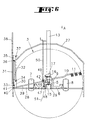
- the rod (39) is articulated by means of the axis (40) on a lug (41) integral with the lever (31) and by means of the axis (42) on a slide (46) which is connected to the connecting beam (13).
- This slide (46) is screwed onto a threaded rod (47) which is held by lugs (48 and 49) integral of the connecting beam (13).
- This threaded rod (47) is free to rotate and locked in translation. It is connected to a crank (50) which allows it to rotate on herself.
- the slide (46) then moves longitudinally on this rod threaded (47). It thus displaces the articulation axis (42) of the rod (39).
- This embodiment therefore actuates the lever (31) so that it pivots around its hinge pin (33) and changes the position of the swath deflector (38) by relative to the rotor (3).
- This embodiment offers a greater choice of positions for the swath deflector (38).
- the threaded rod (47) is advantageously tangent to an arc (51), the center is located on the articulation axis (40) of the rod (39) on the tab (41) of the lever (31) when the machine is in the transport position ( Figure 6). Therefore, the rod (39) and lever (31) automatically bring back the swath deflector (38) against the rotor (3) when placing in the transport position, whatever or its position during work.
- the swather described above can be attached to a tractor using the drawbar (14) and be moved in direction (A).
- the machine When the user arrives at the swath location, the machine is in the transport position in which the rotors (2 and 3) are located one behind the other ( Figure 2).
- To put it in position working (figure 1) it actuates from the tractor the hydraulic cylinder (16) located between the connecting beam (13) and the sleeve (15) so that it lengthens. This one then rotates, via said sleeve (15), the axis (5) substantially vertical of the second rotor (3) on itself.
- the support (6) and the supporting wheels (7 and 8) rotate with said axis (5) and orient themselves towards the left side when look in the direction of travel (A).
- the spacer (29), the support transverse (28) and the protection device (27) also rotate with said axis (5).
- the rod (39) then exerts traction on the tab (41) of the lever (31) of so that it pivots about its hinge pin (33) and moves it away the swath deflector (38) of the rotor (3) automatically.
- the second lever (32) pivots in a similar manner around its axis of articulation (34) so that the deflector (38) is always oriented in the direction of advance (A).
- the desired movement of the deflector (38) can be adjusted according to the volume of the forage to be swathed. So in the if the volume is large, the hinge pin (40) of the rod (39) is placed in the hole (44) of the tab (41) which is closest to the axis of articulation (33) lever (31). This will then pivot outwards as much as possible, in order to obtain a large distance from the rotor (3). On the contrary, if the volume of the the windrow is low, the user will choose an orifice (44) further from the hinge pin (33) of the lever (31). In this case, the pivoting outwards will be weaker, which will favor the formation of a compact swath.
- the spacing between the deflector swath (38) and the rotor (3) is increased when the user moves the slide (46) on the threaded rod (47) in the direction of advance (A).
- the rod (39) then pivots the lever (31) outwards by an angle that can reach 90 °. Lesser spacings are obtained when the slide (46) is located further back on the threaded rod (47). Displacements mentioned above of the slide (46) are made by rotating the threaded rod (47) to using the crank (50).
- the positioning of the axis (40 or 42) of the rod (39) can be carried out before entering the working position or at any time during work.
- the user After rotating the substantially vertical axis (5) as described previously the user moves the machine in direction (A). He can too perform both operations simultaneously.
- the carrying wheels (7 and 8) make then turn the connecting beam (13) around the substantially vertical axis (4) of the first rotor (2) until they are oriented in the direction again progress (A).
- the second rotor (3) In this new position the second rotor (3) is offset relative to the first rotor (2).
- the user actuates the cylinder hydraulic (20) of the holding device (18) so that it shortens. he then tightens the spring (19) which exerts a traction on the connecting beam (13). This therefore remains in the oblique position under all conditions.
- the user actuates the hydraulic means of the supports (6) so lifting the rotors (2 and 3) and clearing the forks (11) from the ground. Then he actuates the hydraulic cylinder (16) so that it shortens and turns the sleeve (15), the substantially vertical axis (5) and the support (6) with the carrying wheels (7 and 8). The latter then pivot to the right and orient in a direction which is parallel to the connecting beam (13).
- the support (28) of the protection device (27) also rotates with the sleeve (15) to the right.
- the rod (39) exercises then a pressure on the tab (41) and makes the lever (31) pivot around its axis hinge (33) so that it automatically returns the swath deflector (38) against the rotor (3).
- the second lever (32) pivots in the same way around of its axis of articulation (34). These two levers (31 and 32) thus position the deflector (38) in a position parallel to the connecting beam (13).
- the deflector (38) is automatically brought back against the rotor (3), in order to obtain a maximum reduction of the width of the machine during transport.
- the control of the hydraulic cylinders (16 and 20) can be synchronized from so as to simplify the work of the user.
Landscapes
- Environmental Sciences (AREA)
- Life Sciences & Earth Sciences (AREA)
- Harvesting Machines For Specific Crops (AREA)
- Control Of Multiple Motors (AREA)
- Glass Compositions (AREA)
- Paper (AREA)
- Agricultural Machines (AREA)
- Handcart (AREA)
- Making Paper Articles (AREA)
- Apparatus For Radiation Diagnosis (AREA)
- Forklifts And Lifting Vehicles (AREA)
- Processes Of Treating Macromolecular Substances (AREA)
- Separation By Low-Temperature Treatments (AREA)
- Compounds Of Unknown Constitution (AREA)
- Instructional Devices (AREA)
Applications Claiming Priority (2)
| Application Number | Priority Date | Filing Date | Title |
|---|---|---|---|
| FR9614819A FR2756137B1 (fr) | 1996-11-26 | 1996-11-26 | Machine de fenaison, notamment une andaineuse avec un deflecteur d'andainage reglage automatiquement dans differentes positions |
| FR9614819 | 1996-11-26 |
Publications (2)
| Publication Number | Publication Date |
|---|---|
| EP0845199A1 EP0845199A1 (fr) | 1998-06-03 |
| EP0845199B1 true EP0845199B1 (fr) | 2001-05-30 |
Family
ID=9498283
Family Applications (1)
| Application Number | Title | Priority Date | Filing Date |
|---|---|---|---|
| EP97440109A Expired - Lifetime EP0845199B1 (fr) | 1996-11-26 | 1997-11-18 | Machine de fenaison |
Country Status (7)
| Country | Link |
|---|---|
| US (1) | US6050076A (da) |
| EP (1) | EP0845199B1 (da) |
| AT (1) | ATE201556T1 (da) |
| DE (1) | DE69705013T2 (da) |
| DK (1) | DK0845199T3 (da) |
| ES (1) | ES2157056T3 (da) |
| FR (1) | FR2756137B1 (da) |
Cited By (1)
| Publication number | Priority date | Publication date | Assignee | Title |
|---|---|---|---|---|
| DE202016007555U1 (de) | 2016-12-12 | 2018-03-22 | Pöttinger Landtechnik Gmbh | Landwirtschaftliche Arbeitsmaschine |
Families Citing this family (9)
| Publication number | Priority date | Publication date | Assignee | Title |
|---|---|---|---|---|
| DE29806999U1 (de) * | 1998-04-17 | 1998-07-23 | Multinorm B.V., Nieuw-Vennep | Heuwerbungsmaschine |
| FR2790358B1 (fr) * | 1999-03-05 | 2001-05-11 | Kuhn Sa | Machine de fenaison avec au moins un rotor d'andainage muni d'un deflecteur dont la position est reglable |
| FR2790637B1 (fr) * | 1999-03-12 | 2001-04-27 | Mecanique Et Tolerie M E C A T | Andaineuse tractee a deux rotors de ratelage |
| DE10017967A1 (de) * | 2000-04-12 | 2001-10-18 | Claas Saulgau Gmbh | Heuwerbungsmaschine |
| DE202004008500U1 (de) * | 2004-05-28 | 2005-10-06 | Kverneland Gottmadingen Gmbh & Co. Kg | Geschleppter Kreiselschwader |
| FR2875377B1 (fr) * | 2004-09-23 | 2007-01-19 | Kuhn Sa Sa | Andaineuse de vegetaux avec trois roues rateleuses |
| FR3000870A1 (fr) * | 2013-01-17 | 2014-07-18 | Kuhn | Machine de fenaison comportant un deflecteur perfectionne |
| FR3019440B1 (fr) * | 2014-04-08 | 2016-03-25 | Kuhn Sa | Machine pour la recolte de fourrage presentant un deflecteur perfectionne |
| GB201610834D0 (en) * | 2016-06-21 | 2016-08-03 | Agco Feucht Gmbh | Agricultural tool control system |
Family Cites Families (32)
| Publication number | Priority date | Publication date | Assignee | Title |
|---|---|---|---|---|
| FR1327063A (fr) * | 1962-03-05 | 1963-05-17 | Arracheuse de betteraves à dispositif rangeur réglable | |
| NL6511984A (nl) * | 1965-09-15 | 1967-03-16 | Lely Nv C Van Der | Inrichting voor het verplaatsen van op de grond liggend gewas |
| DE1582297A1 (de) * | 1965-09-15 | 1970-08-06 | Lely Nv C Van Der | Heuwerbungsmaschine |
| NL6513220A (nl) * | 1965-10-13 | 1967-04-14 | Lely Nv C Van Der | Inrichting voor het bewerken van op de grond liggend gewas |
| DE1507324C3 (de) * | 1966-06-24 | 1978-05-11 | Maschinenfabrik Fahr Ag, 7702 Gottmadingen | Kreiselzettwender |
| NL6713676A (da) * | 1967-10-09 | 1969-04-11 | ||
| CH499254A (de) * | 1968-08-27 | 1970-11-30 | Bucher Guyer Ag Masch | Heuerntemaschine |
| CH508332A (de) * | 1969-04-16 | 1971-06-15 | Kuhn Freres & Cie | Heuerntemaschine |
| CA951910A (en) * | 1971-06-02 | 1974-07-30 | John K. Hale | Cooperating windrowing structure for a rotor type raking device |
| DE2127701B1 (de) * | 1971-06-04 | 1972-10-19 | Wilhelm Stoll, Maschinenfabrik Gmbh, 3325 Broistedt | Heuwerbungsmaschine |
| NL7305169A (da) * | 1973-04-13 | 1974-10-15 | ||
| CA1039515A (en) * | 1973-10-12 | 1978-10-03 | C. Van Der Lely N.V. | Raking machines |
| CH579342A5 (da) * | 1973-10-12 | 1976-09-15 | Lely Nv C Van Der | |
| FR2339330A1 (fr) * | 1976-01-30 | 1977-08-26 | Kuhn Sa | Machine de fenaison pour le fanage et pour l'andainage |
| FR2342639A1 (fr) * | 1976-03-05 | 1977-09-30 | Kuhn Sa | Dispositif permettant la modification de l'angle de piquage des toupies d'une machine agricole du type faneuse-andaineuse |
| NL7607093A (nl) * | 1976-06-29 | 1978-01-02 | Texas Industries Inc | Machine voor het bewerken van gewas. |
| ES237110Y (es) * | 1978-07-05 | 1979-01-16 | Apero de labranza. | |
| FR2549342B1 (fr) * | 1983-07-19 | 1987-10-02 | Kuhn Sa | Machine de fenaison perfectionnee pour le fanage |
| FR2576744B1 (fr) * | 1985-02-06 | 1988-06-17 | Kuhn Sa | Perfectionnement aux jupes flexibles pour deplacer des produits se trouvant sur le sol et machines agricoles equipees de telles jupes |
| FR2582186B1 (fr) * | 1985-05-21 | 1989-05-05 | Kuhn Sa | Perfectionnement aux machines de fenaison munies de plusieurs roues rateleuses |
| FR2613177B1 (fr) * | 1987-04-01 | 1991-06-28 | Kuhn Sa | Machine de fenaison |
| FR2632810B2 (fr) * | 1987-11-17 | 1991-08-30 | Kuhn Sa | Machine de fenaison avec au moins une roue rateleuse equipee de bras porte-outils commandes |
| FR2631775B1 (fr) * | 1988-05-26 | 1991-10-11 | Kuhn Sa | Machine agricole comportant au moins un rotor entraine en rotation durant le travail |
| FR2632155B1 (fr) * | 1988-06-03 | 1991-10-11 | Kuhn Sa | Machine de fenaison comportant un rotor pour andainer |
| FR2644320B1 (fr) * | 1989-03-20 | 1992-05-07 | Kuhn Sa | Machine agricole avec au moins un rotor pour deplacer des produits se trouvant sur le sol |
| FR2648310B1 (fr) * | 1989-06-16 | 1991-09-20 | Kuhn Sa | Machine agricole pour l'andainage, comportant des bras porte-outils repliables |
| DE4021812C2 (de) * | 1989-07-10 | 2000-08-10 | Stoll Maschf Gmbh Wilhelm | Heuwerbungsmaschine |
| FR2661312B1 (fr) * | 1990-04-27 | 1992-07-17 | Kuhn Sa | Machine de fenaison avec plusieurs rotors. |
| FR2678804B1 (fr) * | 1991-07-11 | 1998-09-18 | Kuhn Sa | Machine de fenaison comportant au moins une roue rateleuse, un dispositif de protection et un deflecteur reglable. |
| FR2700916B1 (fr) * | 1993-01-29 | 1999-02-26 | Kuhn Sa | Machine de fenaison avec un deflecteur lateral reglable. |
| FR2719443B1 (fr) * | 1994-05-04 | 1996-07-05 | Kuhn Sa | Machine de fenaison, notamment un andaineur de fourrage. |
| FR2722365B1 (fr) * | 1994-07-13 | 1996-09-20 | Kuhn Sa Societe Anonyme | Machine de fenaison, notamment une andaineuse de vegetaux a bras porte-fourches commandes |
-
1996
- 1996-11-26 FR FR9614819A patent/FR2756137B1/fr not_active Expired - Fee Related
-
1997
- 1997-11-18 DK DK97440109T patent/DK0845199T3/da active
- 1997-11-18 DE DE69705013T patent/DE69705013T2/de not_active Expired - Lifetime
- 1997-11-18 ES ES97440109T patent/ES2157056T3/es not_active Expired - Lifetime
- 1997-11-18 EP EP97440109A patent/EP0845199B1/fr not_active Expired - Lifetime
- 1997-11-18 AT AT97440109T patent/ATE201556T1/de active
- 1997-11-24 US US08/977,683 patent/US6050076A/en not_active Expired - Lifetime
Cited By (2)
| Publication number | Priority date | Publication date | Assignee | Title |
|---|---|---|---|---|
| DE202016007555U1 (de) | 2016-12-12 | 2018-03-22 | Pöttinger Landtechnik Gmbh | Landwirtschaftliche Arbeitsmaschine |
| EP3332628A1 (de) | 2016-12-12 | 2018-06-13 | PÖTTINGER Landtechnik GmbH | Landwirtschaftliche arbeitsmaschine |
Also Published As
| Publication number | Publication date |
|---|---|
| DE69705013T2 (de) | 2002-01-03 |
| DE69705013D1 (de) | 2001-07-05 |
| US6050076A (en) | 2000-04-18 |
| ES2157056T3 (es) | 2001-08-01 |
| ATE201556T1 (de) | 2001-06-15 |
| FR2756137A1 (fr) | 1998-05-29 |
| FR2756137B1 (fr) | 1999-01-22 |
| DK0845199T3 (da) | 2001-09-17 |
| EP0845199A1 (fr) | 1998-06-03 |
Similar Documents
| Publication | Publication Date | Title |
|---|---|---|
| EP0429381B1 (fr) | Machine agricole avec dispositif de suspension du groupe d'organes de travail perfectionné | |
| EP0763321B1 (fr) | Machine de fenaison | |
| EP0845199B1 (fr) | Machine de fenaison | |
| EP1290936B1 (fr) | Machine de fenaison | |
| EP1076482B1 (fr) | Machine de fenaison avec au moins un rotor d'andainage muni d'un deflecteur dont la position est reglable | |
| EP0692185B1 (fr) | Machine de fenaison, notamment une andaineuse à bras porte-fourches commandés | |
| EP0514302B1 (fr) | Andaineuse de végétaux perfectionnée | |
| EP0772969A1 (fr) | Machine de fenaison comportant au moins un rotor d'andainage | |
| FR2664127A1 (fr) | Machine agricole, notamment une andaineuse de vegetaux, a largeur de travail reglable. | |
| EP0797913B1 (fr) | Machine de fenaison | |
| FR2759245A1 (fr) | Machine de fenaison avec un dispositif d'appui au sol incluant au moins un balancier avec deux roues porteuses et un moyen pour deplacer ce balancier en vue du transport | |
| EP0779022B1 (fr) | Machine de fenaison | |
| EP0426588A1 (fr) | Perfectionnement aux machines agricoles destinées notamment à la fenaison | |
| FR2707450A1 (fr) | Machine de fenaison avec des rotors de fanage ou d'andainage munis de roues d'appui au sol. | |
| EP0654209B1 (fr) | Machine de fenaison | |
| EP0733302B1 (fr) | Machine de fenaison | |
| EP0532443B1 (fr) | Machine de fenaison comportant des roulettes orientables | |
| EP0914766B1 (fr) | Machine de fenaison | |
| EP4272538A1 (fr) | Machine de fenaison sécurisée et protocole s'y rapportant | |
| EP0811314B1 (fr) | Machine agricole | |
| FR2798817A1 (fr) | Machine de fenaison, notamment une andaineuse avec plusieurs rotors s'appuyant sur le sol au moyen de roues porteuses | |
| FR2549686A1 (fr) | Faneuse avec organes porteurs et arbres d'entrainement repliables | |
| EP0998843A1 (fr) | Machine de fenaison |
Legal Events
| Date | Code | Title | Description |
|---|---|---|---|
| PUAI | Public reference made under article 153(3) epc to a published international application that has entered the european phase |
Free format text: ORIGINAL CODE: 0009012 |
|
| AK | Designated contracting states |
Kind code of ref document: A1 Designated state(s): AT DE DK ES FR GB IT NL |
|
| AX | Request for extension of the european patent |
Free format text: AL;LT;LV;MK;RO;SI |
|
| 17P | Request for examination filed |
Effective date: 19981116 |
|
| AKX | Designation fees paid |
Free format text: AT DE DK ES FR GB IT NL |
|
| RBV | Designated contracting states (corrected) |
Designated state(s): AT DE DK ES FR GB IT NL |
|
| GRAG | Despatch of communication of intention to grant |
Free format text: ORIGINAL CODE: EPIDOS AGRA |
|
| GRAG | Despatch of communication of intention to grant |
Free format text: ORIGINAL CODE: EPIDOS AGRA |
|
| GRAH | Despatch of communication of intention to grant a patent |
Free format text: ORIGINAL CODE: EPIDOS IGRA |
|
| 17Q | First examination report despatched |
Effective date: 20000927 |
|
| GRAH | Despatch of communication of intention to grant a patent |
Free format text: ORIGINAL CODE: EPIDOS IGRA |
|
| GRAA | (expected) grant |
Free format text: ORIGINAL CODE: 0009210 |
|
| AK | Designated contracting states |
Kind code of ref document: B1 Designated state(s): AT DE DK ES FR GB IT NL |
|
| REF | Corresponds to: |
Ref document number: 201556 Country of ref document: AT Date of ref document: 20010615 Kind code of ref document: T |
|
| ITF | It: translation for a ep patent filed | ||
| REF | Corresponds to: |
Ref document number: 69705013 Country of ref document: DE Date of ref document: 20010705 |
|
| REG | Reference to a national code |
Ref country code: ES Ref legal event code: FG2A Ref document number: 2157056 Country of ref document: ES Kind code of ref document: T3 |
|
| GBT | Gb: translation of ep patent filed (gb section 77(6)(a)/1977) |
Effective date: 20010810 |
|
| REG | Reference to a national code |
Ref country code: DK Ref legal event code: T3 |
|
| REG | Reference to a national code |
Ref country code: GB Ref legal event code: IF02 |
|
| PLBE | No opposition filed within time limit |
Free format text: ORIGINAL CODE: 0009261 |
|
| STAA | Information on the status of an ep patent application or granted ep patent |
Free format text: STATUS: NO OPPOSITION FILED WITHIN TIME LIMIT |
|
| 26N | No opposition filed | ||
| REG | Reference to a national code |
Ref country code: FR Ref legal event code: PLFP Year of fee payment: 19 |
|
| PGFP | Annual fee paid to national office [announced via postgrant information from national office to epo] |
Ref country code: DK Payment date: 20151022 Year of fee payment: 19 |
|
| PGFP | Annual fee paid to national office [announced via postgrant information from national office to epo] |
Ref country code: DE Payment date: 20151022 Year of fee payment: 19 Ref country code: GB Payment date: 20151027 Year of fee payment: 19 Ref country code: IT Payment date: 20151023 Year of fee payment: 19 |
|
| PGFP | Annual fee paid to national office [announced via postgrant information from national office to epo] |
Ref country code: AT Payment date: 20151022 Year of fee payment: 19 Ref country code: ES Payment date: 20151110 Year of fee payment: 19 Ref country code: NL Payment date: 20151021 Year of fee payment: 19 Ref country code: FR Payment date: 20151023 Year of fee payment: 19 |
|
| REG | Reference to a national code |
Ref country code: DE Ref legal event code: R119 Ref document number: 69705013 Country of ref document: DE |
|
| REG | Reference to a national code |
Ref country code: DK Ref legal event code: EBP Effective date: 20161130 |
|
| REG | Reference to a national code |
Ref country code: NL Ref legal event code: MM Effective date: 20161201 |
|
| REG | Reference to a national code |
Ref country code: AT Ref legal event code: MM01 Ref document number: 201556 Country of ref document: AT Kind code of ref document: T Effective date: 20161118 |
|
| GBPC | Gb: european patent ceased through non-payment of renewal fee |
Effective date: 20161118 |
|
| REG | Reference to a national code |
Ref country code: FR Ref legal event code: ST Effective date: 20170731 |
|
| PG25 | Lapsed in a contracting state [announced via postgrant information from national office to epo] |
Ref country code: AT Free format text: LAPSE BECAUSE OF NON-PAYMENT OF DUE FEES Effective date: 20161118 |
|
| PG25 | Lapsed in a contracting state [announced via postgrant information from national office to epo] |
Ref country code: NL Free format text: LAPSE BECAUSE OF NON-PAYMENT OF DUE FEES Effective date: 20161201 |
|
| PG25 | Lapsed in a contracting state [announced via postgrant information from national office to epo] |
Ref country code: FR Free format text: LAPSE BECAUSE OF NON-PAYMENT OF DUE FEES Effective date: 20161130 Ref country code: IT Free format text: LAPSE BECAUSE OF NON-PAYMENT OF DUE FEES Effective date: 20161118 |
|
| PG25 | Lapsed in a contracting state [announced via postgrant information from national office to epo] |
Ref country code: GB Free format text: LAPSE BECAUSE OF NON-PAYMENT OF DUE FEES Effective date: 20161118 Ref country code: DE Free format text: LAPSE BECAUSE OF NON-PAYMENT OF DUE FEES Effective date: 20170601 Ref country code: DK Free format text: LAPSE BECAUSE OF NON-PAYMENT OF DUE FEES Effective date: 20161130 |
|
| REG | Reference to a national code |
Ref country code: ES Ref legal event code: FD2A Effective date: 20180507 |
|
| PG25 | Lapsed in a contracting state [announced via postgrant information from national office to epo] |
Ref country code: ES Free format text: LAPSE BECAUSE OF FAILURE TO SUBMIT A TRANSLATION OF THE DESCRIPTION OR TO PAY THE FEE WITHIN THE PRESCRIBED TIME-LIMIT Effective date: 20010530 |
|
| PG25 | Lapsed in a contracting state [announced via postgrant information from national office to epo] |
Ref country code: ES Free format text: LAPSE BECAUSE OF FAILURE TO SUBMIT A TRANSLATION OF THE DESCRIPTION OR TO PAY THE FEE WITHIN THE PRESCRIBED TIME-LIMIT Effective date: 20161119 |