EP0845189B1 - Reseau de communication video - Google Patents
Reseau de communication video Download PDFInfo
- Publication number
- EP0845189B1 EP0845189B1 EP97923282A EP97923282A EP0845189B1 EP 0845189 B1 EP0845189 B1 EP 0845189B1 EP 97923282 A EP97923282 A EP 97923282A EP 97923282 A EP97923282 A EP 97923282A EP 0845189 B1 EP0845189 B1 EP 0845189B1
- Authority
- EP
- European Patent Office
- Prior art keywords
- video communication
- channels
- frequency band
- cable
- communication channels
- Prior art date
- Legal status (The legal status is an assumption and is not a legal conclusion. Google has not performed a legal analysis and makes no representation as to the accuracy of the status listed.)
- Expired - Lifetime
Links
Images
Classifications
-
- H—ELECTRICITY
- H04—ELECTRIC COMMUNICATION TECHNIQUE
- H04N—PICTORIAL COMMUNICATION, e.g. TELEVISION
- H04N7/00—Television systems
- H04N7/20—Adaptations for transmission via a GHz frequency band, e.g. via satellite
-
- H—ELECTRICITY
- H04—ELECTRIC COMMUNICATION TECHNIQUE
- H04N—PICTORIAL COMMUNICATION, e.g. TELEVISION
- H04N7/00—Television systems
- H04N7/10—Adaptations for transmission by electrical cable
- H04N7/102—Circuits therefor, e.g. noise reducers, equalisers, amplifiers
Definitions
- the present invention relates to a method of increasing the capacity expressed in a number of channels of a video communication signal distribution network in which a first set of video communication channels received by satellite is converted into a predetermined frequency band in order to be delivered by a distribution cable and used by at least one user apparatus capable of using channels in a predetermined frequency band.
- the invention also relates to a video communication signal distribution network, comprising a distribution cable, at least one signal tapping element for supplying, from the cable, signals to at least one user apparatus capable of using channels in a predetermined frequency band, at least one converter delivering by said cable, in said predetermined frequency band, a first set of video communication channels received by satellite.
- the invention likewise relates to a video communication network head-end and to a signal tapping element to be used in such a video communication signal distribution network.
- a video communication signal distribution network is known from Patent EP 0 583 830. According to this document, a plurality of cables are used, each transporting different set of video communication channels, all situated in the band likely to be used by a user apparatus, and a switch at the level of the signal tapping element permitting to select the desired cable.
- At least a second set of video communication channels received by satellite is converted into a frequency band situated completely above said predetermined frequency band in order to be distributed by the same distribution cable as said first set of video communication channels, and for use in a user apparatus said second set of video communication channels is restored in said predetermined frequency band.
- a frequency band is used having the same bandwidth as for the first set, and a gap is left open between the frequency band of the second set of video communication channels and the frequency band of the first set of video communication channels.
- a video communication network comprises at least a frequency translation module for translating at least a second set of video communication channels received by satellite, into a frequency band situated completely above said predetermined frequency band, said second set of video communication channel being distributed by said cable with said first set of video communication channels, said tapping element comprising a converter module for restoring said second set of video communication channels in said predetermined band, and a switch for connecting said user apparatus either directly to the cable or to said converter module upon user request.
- a gap of at least 100 MHz is provided between the frequency band of the first set of video communication channels and the frequency band of the second set of video communication channels.
- a video communication network head-end comprises a frequency translation module for translating at least a second set of video communication channels received by satellite into a frequency band situated completely above said predetermined frequency band in order to distribute said first and second video communication channels by the same cable.
- a signal tapping element comprises a converter module for restoring said second set of video communication channels in said predetermined band, and a switch for connecting said user apparatus either directly to said cable or to said converter module upon user request.
- the value of the frequency translation provided by the translation means is at least equal to 1300 MHz.
- the means for switching or not the translation means into circuit are actuated either by the presence of a 14 to 18 volts control voltage, or by the presence or absence of a 22 kHz AC voltage.
- French patent application 2662895 describes the translation of TV signals coming from satellites into the band 300MHz-900MHz for transmission over the distribution network to the TV receivers. At the TV receiver, these TV signals are retranslated in the band which is used by the television receiver (950MHz-1750MHz). The aim of this translation is to make it possible to use, in the distribution network, standard products developed for operating till 862MHz.
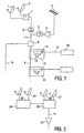
- the network shown in Fig. 1 comprises a network head-end, at least one distribution cable, and at least one signal tapping element.
- the network head-end shown in its simplest form here, comprises two dish antennas 1 and 2 for satellite television reception, and a module 7 for frequency translation for the dish antenna 2.
- the dish antennas 1 and 2 can receive each forty channels having a bandwidth of 30 MHz and have each an integrated conversion block called "LNB", producing the channels in the 950-2150 MHz frequency band.
- the module 7 translates the channels coming from the dish antenna 2 to form forty channels having a bandwidth of 30 MHz each, in the 2250-3450 MHz frequency band.
- Signal tapping elements or splitters 12 are connected to the cable 9, each feeding a user apparatus, for example, a receiver decoder 18 connected to the splitter 12 by a user cable 10 and capable of utilizing channels in a predetermined frequency band which is habitually the 950-2150 MHz frequency band.
- Each splitter contains a frequency converter module 13 which lowers the frequencies of the signals received in its input by 1300 MHz.
- the band running from 2250 to 3450 MHz is converted to a band running from 950 to 2150 MHz, which corresponds to the band that can be used by a receiver/decoder.
- a switch 14 makes it possible to connect the user apparatus either directly to the cable, or to the output of the converter module 14.
- the receiver decoder will be capable of processing either directly the channels of the 950-2150 MHz band of the cable, or the channels of the 2250-3450 MHz band of the cable, converted to the 950-2150 MHz band by the converter 13.
- the network head-end represented in Fig. 2 forms a variant which may be used in lieu of the elements 1, 2, 7 of Fig. 1. It comprises four dish antennas 22, 23, 26, 27 comprising each a LNB which produces channels having a bandwidth of 30 MHz each in a 950-2150 MHz band.
- the module 24 derives forty satellite channels having each a bandwidth of 30 MHz chosen from all the channels received by the two dish antennas 22 and 23, and translates each of them into a separate channel of the 2250-3450 MHz band.
- the module 29 selects forty channels having each a bandwidth of 30 MHz, chosen from all the channels received by the two dish antennas 26 and 27, each in a separate channel of the 950-2150 MHz band, adds thereto the channels coming from module 24 and applies all of them to the cable 11, while all the 950-3450 MHz channels are finally amplified in an amplifier 25.
- each of the satellite channels directly to a converted frequency of the 2250-3450 MHz band, in a LNB provided for this purpose. This can be contemplated economically if the quantities are sufficient to permit the financial settlement of the development of a specific LNB.
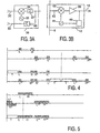
- Fig. 3A represents a transposer, for example, the one referenced 7 in the basic arrangement of Fig. 1. It receives on cable 32 the channels coming from the dish antenna 2 and on the cable 33 the channels coming from the dish antenna 1.
- a modulator or mixer 34 of any known type is fed by an oscillator 35.
- the output signal of the mixer 34 is applied to the cable 11 via a high-pass filter 37 which passes the frequencies higher than or equal to 2250 MHz.
- the result of mixer 34 is that the channels arriving at the input 32 in the 2250-3450 MHz band are converted to the 950-2150 MHz band.
- the signal on the input 33 passes without a frequency change on cable 11, via a low-pass filter 36 which passes the frequencies lower than or equal 2150 MHz.
- Fig. 3B represents an embodiment of the splitter referenced 12 in Fig. 1.
- a resistor 43 makes it possible to tap the whole signal coming from cable 9 in known manner while the impedance is adapted, and the tapped signal is taken to a modulator or mixer 42 of any known type (active-circuit, Gilbert, transformer, etc.).
- This mixer is fed by an oscillator 41.
- the result of the mixer is that the channels of the 2250-3450 MHz band present on cable 9 are converted to the 950-2150 MHz band.
- This mixer is of a model that produces shifted channels on the output, but whose incoming channels are suppressed or at least attenuated considerably.
- the signal on the output of the mixer 42 is amplified by an amplifier 39 and leaves by cable 10.
- the user apparatus of Fig. 1 sends an information signal to indicate whether they are the channels using the upper side band of the 950-2150 MHz band of the cable which are desired, or whether they are the channels converted to the 2250-3450 MHz band.
- This information signal, produced by the user apparatus may, for example, consist of the fact that a DC control voltage has a value of 14 or 18 volts, or also of the fact that a 22 kHz AC voltage is present or not, or may also be an information signal of the type "DiSEqC" in which a 22 kHz AC voltage is switched to form words.
- the module 40 connected to cable 10, detects the information concerned and controls the oscillator 41 to operate or stop.
- the first line represents channels in the 950-2150 MHz band, such as produced by a LNB, those indicated L positioned low in the band, those indicated H positioned high in the band.
- a 4400 MHz oscillator has been chosen whose frequency is indicated by a vertical broken line.
- the mixer 34 of Fig. 3A produces the channels indicated on the second line.
- the channels L and H became, respectively:
- the signals finally applied to cable 9 are indicated on the third line, the addition of the various channels producing a "terrestrial" band, denoted T (47-860 MHz), a L-H band (950-2150 MHz) coming, for example, from the dish antenna 1 of Fig. 1, and a band H*-L* (2250-3450 MHz) obtained by frequency translation.
- the oscillator 41 of the mixer 42 is also working at 4400 MHz, and when the signals pass through this mixer, channels indicated on the fourth line are produced: the band T gives the band T ⁇ , the band H*-L* gives the band L* ⁇ -H* ⁇ , the band L-H gives the band H ⁇ -L ⁇ , with, furthermore, the corresponding bands indicated by ⁇ above the frequency of the oscillator.
- the band L-H of the third line is stopped by the mixer. Only the band L* ⁇ -H* ⁇ , whose channels are in the right order, is likely to be used by a user apparatus.
- a 1300 MHz oscillator has been chosen, that means, in the band L-H.
- the mixer 34 of Fig. 3A produces the channels indicated on the second line.
- the channels below 1300 MHz are called L
- the channels above 1300 MHz are called H.
- the channels L and H are the result of the subtraction of the value of 1300 MHz from the value of their frequency, the channels L* and H* ranging from 0 to 850 MHz, but with an overlap (the channels H* are indicated upside down for clarity).
- the channels L** and H** are obtained, ranging from 2250 to 3450 MHz.
- the distributor 8 of Fig. 1 could also be omitted (a single cable), or, on the contrary, serve more than two cables, for example, four; the splitter casings 12, 15 could contain each, for example, two or four assemblies such as 13 + 14 to serve two or four users; the converted band could also be placed at even higher frequencies (higher than 2250-3450 MHz) to obtain a gap larger than 100 MHz between the bands; in the case of digital television channels, the 40 channels of 30 MHz could be 30 channels of 40 MHz bandwidth.
Landscapes
- Engineering & Computer Science (AREA)
- Multimedia (AREA)
- Signal Processing (AREA)
- Physics & Mathematics (AREA)
- Astronomy & Astrophysics (AREA)
- General Physics & Mathematics (AREA)
- Details Of Television Systems (AREA)
- Input Circuits Of Receivers And Coupling Of Receivers And Audio Equipment (AREA)
Claims (10)
- Procédé pour accroítre la capacité exprimée en un nombre de canaux d'un réseau de distribution de signaux de communication vidéo dans lequel un premier jeu de canaux de communication vidéo reçus par satellite (1) sont convertis en une bande de fréquences prédéterminée afin d'être fournis par un câble de distribution (11) et utilisés par au moins un appareil utilisateur (18) capable d'utiliser des canaux dans une bande de fréquences prédéterminée,
caractérisé en ce qu'au moins un deuxième jeu de canaux de communication vidéo reçus par satellite (2) sont convertis en une bande de fréquences située totalement au-dessus de ladite bande de fréquences prédéterminée afin d'être distribués par le même câble de distribution (11) que ledit premier jeu de canaux de communication vidéo, et en ce que, pour utilisation dans un appareil utilisateur, ledit deuxième jeu de canaux de communication vidéo sont rétablis dans ladite bande de fréquences prédéterminée. - Procédé suivant la revendication 1, caractérisé en ce que, pour le deuxième jeu de canaux convertis, une bande de fréquences présentant la même largeur de bande que pour le premier jeu est utilisée.
- Procédé suivant la revendication 1, caractérisé en ce qu'un intervalle est laissé libre entre la bande de fréquences du deuxième jeu de canaux convertis et la bande de fréquences du premier jeu de canaux convertis.
- Réseau de distribution de signaux de communication vidéo comprenant un câble de distribution (11), au moins un élément de dérivation de signaux (12,15) pour fournir, depuis le câble, des signaux à au moins un appareil utilisateur (18) capable d'utiliser des canaux dans une bande de fréquences prédéterminée, au moins un convertisseur (LNB) fournissant par ledit câble, dans ladite bande de fréquences prédéterminée, un premier jeu de canaux de communication vidéo reçus par satellite (1),
caractérisé en ce qu'il comprend au moins un module de transposition de fréquence (LNB, 7) pour transposer au moins un deuxième jeu de canaux de communication vidéo reçus par satellite en une bande de fréquences située totalement au-dessus de ladite bande de fréquences prédéterminée, ledit deuxième jeu de canaux de communication vidéo étant distribués par ledit câble (11) avec ledit premier jeu de canaux de communication vidéo, ledit élément de dérivation comprenant un module convertisseur (13) pour rétablir ledit deuxième jeu de canaux de communication vidéo dans ladite bande prédéterminée, et un commutateur (14) pour connecter ledit appareil utilisateur soit directement au câble, soit audit module convertisseur sur demande de l'utilisateur. - Réseau de communication vidéo suivant la revendication 4, caractérisé en ce qu'un intervalle d'au moins 100 MHz est prévu entre la bande de fréquences du premier jeu de canaux convertis et la bande de fréquences du deuxième jeu de canaux convertis.
- Tête de réseau de communication vidéo comprenant au moins un convertisseur de télédiffusion satellite (LNB) pour convertir un premier jeu de canaux de communication vidéo reçus par satellite (1) en une bande de fréquences prédéterminée, pour fournir ledit premier jeu de canaux de communication vidéo par un câble de distribution (11) à au moins un appareil utilisateur (18) capable d'utiliser des canaux dans ladite bande de fréquences prédéterminée,
caractérisée en ce qu'elle comprend en outre un module de transposition de fréquence (LNB, 7) pour transposer au moins un deuxième jeu de canaux de communication vidéo reçus par satellite (2) en une bande de fréquences située totalement au-dessus de ladite bande de fréquences prédéterminée afin de distribuer lesdits premiers et deuxièmes canaux de communication vidéo par le même câble (11). - Tête de réseau de communication vidéo suivant la revendication 6,
caractérisée en ce que la différence entre la bande de fréquences du premier jeu de canaux convertis et la bande de fréquences du deuxième jeu de canaux convertis est d'au moins 100 MHz. - Elément de dérivation de signaux (12, 15) pour fournir, d'un câble de distribution (11), un premier jeu de canaux de communication vidéo reçus par satellite (1) et convertis en une bande de fréquences prédéterminée à au moins un appareil utilisateur (18) capable d'utiliser des canaux dans ladite bande de fréquences prédéterminée,
caractérisé en ce qu'au moins un deuxième jeu de canaux de communication vidéo reçus par satellite (2) sont transposés en une bande de fréquences située totalement au-dessus de ladite bande de fréquences prédéterminée afin d'être distribués par ledit câble (11) avec ledit premier jeu de canaux de communication vidéo, ledit élément de dérivation comprend un module convertisseur (13) pour rétablir ledit deuxième jeu de canaux de communication vidéo dans ladite bande prédéterminée, et un commutateur (14) pour connecter ledit appareil utilisateur soit directement audit câble, soit audit module convertisseur sur demande de l'utilisateur. - Elément de dérivation de signaux (12, 15) suivant la revendication 8,
caractérisé en ce que la transposition dudit deuxième jeu de canaux de communication vidéo est au moins égale à 1300 MHz. - Elément de dérivation de signaux (12, 15) suivant la revendication 8,
caractérisé en ce que ledit commutateur est commandé soit par la valeur d'une tension de commande continue de 14 volts ou de 18 volts, soit par la présence ou l'absence d'une tension alternative de 22 kHz.
Applications Claiming Priority (3)
| Application Number | Priority Date | Filing Date | Title |
|---|---|---|---|
| FR9607634 | 1996-06-19 | ||
| FR9607634 | 1996-06-19 | ||
| PCT/IB1997/000664 WO1997049240A1 (fr) | 1996-06-19 | 1997-06-09 | Reseau de communication video |
Publications (2)
| Publication Number | Publication Date |
|---|---|
| EP0845189A1 EP0845189A1 (fr) | 1998-06-03 |
| EP0845189B1 true EP0845189B1 (fr) | 2003-09-17 |
Family
ID=9493219
Family Applications (1)
| Application Number | Title | Priority Date | Filing Date |
|---|---|---|---|
| EP97923282A Expired - Lifetime EP0845189B1 (fr) | 1996-06-19 | 1997-06-09 | Reseau de communication video |
Country Status (4)
| Country | Link |
|---|---|
| EP (1) | EP0845189B1 (fr) |
| JP (1) | JPH11511937A (fr) |
| DE (1) | DE69724916T2 (fr) |
| WO (1) | WO1997049240A1 (fr) |
Families Citing this family (6)
| Publication number | Priority date | Publication date | Assignee | Title |
|---|---|---|---|---|
| DE19747447A1 (de) * | 1997-10-28 | 1999-04-29 | Cit Alcatel | Vorrichtung zum Zusammenführen und Verstärken von zwei breitbandigen Signalen |
| DE19749120C2 (de) * | 1997-11-06 | 2002-07-18 | Kathrein Werke Kg | Satelliten-Empfangsanlage sowie zugehöriges Verfahren zum Betrieb einer Antennen-Empfangsanlage |
| IT1299476B1 (it) * | 1998-05-25 | 2000-03-16 | Itel S P A | Sistema per la gestione combinata di segnali |
| US6600730B1 (en) * | 1998-08-20 | 2003-07-29 | Hughes Electronics Corporation | System for distribution of satellite signals from separate multiple satellites on a single cable line |
| EP1030522A1 (fr) * | 1999-02-16 | 2000-08-23 | Koninklijke Philips Electronics N.V. | Procédé pour transmettre des signaux de retour vers un satellite à partir d'un réseau de distribution de signaux de vidéocommunication |
| AU2003293542A1 (en) | 2002-12-11 | 2004-06-30 | R.F. Magic, Inc. | Nxm crosspoint switch with band translation |
Family Cites Families (3)
| Publication number | Priority date | Publication date | Assignee | Title |
|---|---|---|---|---|
| FR2662895B1 (fr) * | 1990-05-29 | 1992-08-28 | Telediffusion Fse | Installation de distribution de programmes de radiodiffusion a reseau cable. |
| FR2680935B1 (fr) * | 1991-08-30 | 1996-08-09 | Telediffusion Fse | Installation a reseau filaire de distribution de programmes audiovisuels et communication numerique a pont de donnees numeriques. |
| EP0583830A1 (fr) * | 1992-08-19 | 1994-02-23 | Philips Electronique Grand Public | Boîtier de raccordement à un système de distribution de signaux de télévision, et système de distribution avec des moyens de sélection |
-
1997
- 1997-06-09 WO PCT/IB1997/000664 patent/WO1997049240A1/fr active IP Right Grant
- 1997-06-09 JP JP10502593A patent/JPH11511937A/ja not_active Withdrawn
- 1997-06-09 EP EP97923282A patent/EP0845189B1/fr not_active Expired - Lifetime
- 1997-06-09 DE DE69724916T patent/DE69724916T2/de not_active Expired - Fee Related
Also Published As
| Publication number | Publication date |
|---|---|
| EP0845189A1 (fr) | 1998-06-03 |
| DE69724916T2 (de) | 2004-07-15 |
| WO1997049240A1 (fr) | 1997-12-24 |
| JPH11511937A (ja) | 1999-10-12 |
| DE69724916D1 (de) | 2003-10-23 |
Similar Documents
| Publication | Publication Date | Title |
|---|---|---|
| US5905941A (en) | Television signal cable distribution installation | |
| US5428404A (en) | Apparatus for method for selectively demodulating and remodulating alternate channels of a television broadcast | |
| USRE39202E1 (en) | Digital video converter box for subscriber/home with multiple television sets | |
| US5742680A (en) | Set top box for receiving and decryption and descrambling a plurality of satellite television signals | |
| US5412720A (en) | Interactive home information system | |
| AU670830B2 (en) | TV set-top converter | |
| US4603349A (en) | Cable television system with stereo sound reproduction | |
| US9179170B2 (en) | Low noise block converter feedhorn | |
| EP1347644B1 (fr) | Système de distribution de signaux par satellite | |
| GB2256115A (en) | Switched cable television networks. | |
| CA2270429A1 (fr) | Systeme de radiodiffusion directe par satellite pour logements multiples | |
| MXPA96006588A (en) | Receptor apparatus, receiving method and termi unit | |
| EP1143733A2 (fr) | Interface de signaux pour un dispositif de communication bidirectionnelle | |
| EP0652677A2 (fr) | Convertisseur pour un système de télédiffusion terrestre de télévision | |
| US4586081A (en) | Method and apparatus for secure audio channel transmission in a CATV system | |
| EP0845189B1 (fr) | Reseau de communication video | |
| JP2001231033A (ja) | 共同受信システム及びこれの端末用周波数変換装置 | |
| RU2212115C2 (ru) | Оптимизированная система для распределения сигналов телевизионных и телекоммуникационных служб от периферийного узла к абонентским терминалам | |
| US7917922B1 (en) | Video input switching and signal processing apparatus | |
| US5386226A (en) | Connection unit for a television signal distribution system | |
| US5532733A (en) | Remodulation of a cable box output signal to a UHF channel | |
| JP3824369B2 (ja) | 衛星受信システム及び電源装置 | |
| JPH09168104A (ja) | 共同受信施設 | |
| EP2680465B1 (fr) | Système de distribution de données audio et/ou vidéo | |
| KR100421836B1 (ko) | 디지탈방송공청시스템 |
Legal Events
| Date | Code | Title | Description |
|---|---|---|---|
| PUAI | Public reference made under article 153(3) epc to a published international application that has entered the european phase |
Free format text: ORIGINAL CODE: 0009012 |
|
| AK | Designated contracting states |
Kind code of ref document: A1 Designated state(s): DE DK ES FI FR GB IT |
|
| RAP3 | Party data changed (applicant data changed or rights of an application transferred) |
Owner name: KONINKLIJKE PHILIPS ELECTRONICS N.V. |
|
| 17P | Request for examination filed |
Effective date: 19980624 |
|
| 17Q | First examination report despatched |
Effective date: 20010917 |
|
| GRAH | Despatch of communication of intention to grant a patent |
Free format text: ORIGINAL CODE: EPIDOS IGRA |
|
| GRAS | Grant fee paid |
Free format text: ORIGINAL CODE: EPIDOSNIGR3 |
|
| GRAA | (expected) grant |
Free format text: ORIGINAL CODE: 0009210 |
|
| AK | Designated contracting states |
Kind code of ref document: B1 Designated state(s): DE DK ES FI FR GB IT |
|
| PG25 | Lapsed in a contracting state [announced via postgrant information from national office to epo] |
Ref country code: IT Free format text: LAPSE BECAUSE OF FAILURE TO SUBMIT A TRANSLATION OF THE DESCRIPTION OR TO PAY THE FEE WITHIN THE PRE;WARNING: LAPSES OF ITALIAN PATENTS WITH EFFECTIVE DATE BEFORE 2007 MAY HAVE OCCURRED AT ANY TIME BEFORE 2007. THE CORRECT EFFECTIVE DATE MAY BE DIFFERENT FROM THE ONE RECORDED.SCRIBED TIME-LIMIT Effective date: 20030917 Ref country code: FI Free format text: LAPSE BECAUSE OF FAILURE TO SUBMIT A TRANSLATION OF THE DESCRIPTION OR TO PAY THE FEE WITHIN THE PRESCRIBED TIME-LIMIT Effective date: 20030917 |
|
| REG | Reference to a national code |
Ref country code: GB Ref legal event code: FG4D |
|
| REF | Corresponds to: |
Ref document number: 69724916 Country of ref document: DE Date of ref document: 20031023 Kind code of ref document: P |
|
| PG25 | Lapsed in a contracting state [announced via postgrant information from national office to epo] |
Ref country code: DK Free format text: LAPSE BECAUSE OF FAILURE TO SUBMIT A TRANSLATION OF THE DESCRIPTION OR TO PAY THE FEE WITHIN THE PRESCRIBED TIME-LIMIT Effective date: 20031217 |
|
| PG25 | Lapsed in a contracting state [announced via postgrant information from national office to epo] |
Ref country code: ES Free format text: LAPSE BECAUSE OF FAILURE TO SUBMIT A TRANSLATION OF THE DESCRIPTION OR TO PAY THE FEE WITHIN THE PRESCRIBED TIME-LIMIT Effective date: 20031228 |
|
| ET | Fr: translation filed | ||
| PGFP | Annual fee paid to national office [announced via postgrant information from national office to epo] |
Ref country code: GB Payment date: 20040629 Year of fee payment: 8 |
|
| PLBE | No opposition filed within time limit |
Free format text: ORIGINAL CODE: 0009261 |
|
| STAA | Information on the status of an ep patent application or granted ep patent |
Free format text: STATUS: NO OPPOSITION FILED WITHIN TIME LIMIT |
|
| PGFP | Annual fee paid to national office [announced via postgrant information from national office to epo] |
Ref country code: DE Payment date: 20040813 Year of fee payment: 8 |
|
| 26N | No opposition filed |
Effective date: 20040618 |
|
| REG | Reference to a national code |
Ref country code: GB Ref legal event code: 746 Effective date: 20050518 |
|
| PG25 | Lapsed in a contracting state [announced via postgrant information from national office to epo] |
Ref country code: GB Free format text: LAPSE BECAUSE OF NON-PAYMENT OF DUE FEES Effective date: 20050609 |
|
| PGFP | Annual fee paid to national office [announced via postgrant information from national office to epo] |
Ref country code: FR Payment date: 20050628 Year of fee payment: 9 |
|
| PG25 | Lapsed in a contracting state [announced via postgrant information from national office to epo] |
Ref country code: DE Free format text: LAPSE BECAUSE OF NON-PAYMENT OF DUE FEES Effective date: 20060103 |
|
| GBPC | Gb: european patent ceased through non-payment of renewal fee |
Effective date: 20050609 |
|
| REG | Reference to a national code |
Ref country code: FR Ref legal event code: ST Effective date: 20070228 |
|
| PG25 | Lapsed in a contracting state [announced via postgrant information from national office to epo] |
Ref country code: FR Free format text: LAPSE BECAUSE OF NON-PAYMENT OF DUE FEES Effective date: 20060630 |