EP0845189B1 - Video communication network - Google Patents
Video communication network Download PDFInfo
- Publication number
- EP0845189B1 EP0845189B1 EP97923282A EP97923282A EP0845189B1 EP 0845189 B1 EP0845189 B1 EP 0845189B1 EP 97923282 A EP97923282 A EP 97923282A EP 97923282 A EP97923282 A EP 97923282A EP 0845189 B1 EP0845189 B1 EP 0845189B1
- Authority
- EP
- European Patent Office
- Prior art keywords
- video communication
- channels
- frequency band
- cable
- communication channels
- Prior art date
- Legal status (The legal status is an assumption and is not a legal conclusion. Google has not performed a legal analysis and makes no representation as to the accuracy of the status listed.)
- Expired - Lifetime
Links
Images
Classifications
-
- H—ELECTRICITY
- H04—ELECTRIC COMMUNICATION TECHNIQUE
- H04N—PICTORIAL COMMUNICATION, e.g. TELEVISION
- H04N7/00—Television systems
- H04N7/20—Adaptations for transmission via a GHz frequency band, e.g. via satellite
-
- H—ELECTRICITY
- H04—ELECTRIC COMMUNICATION TECHNIQUE
- H04N—PICTORIAL COMMUNICATION, e.g. TELEVISION
- H04N7/00—Television systems
- H04N7/10—Adaptations for transmission by electrical cable
- H04N7/102—Circuits therefor, e.g. noise reducers, equalisers, amplifiers
Landscapes
- Engineering & Computer Science (AREA)
- Multimedia (AREA)
- Signal Processing (AREA)
- Physics & Mathematics (AREA)
- Astronomy & Astrophysics (AREA)
- General Physics & Mathematics (AREA)
- Details Of Television Systems (AREA)
- Input Circuits Of Receivers And Coupling Of Receivers And Audio Equipment (AREA)
Description
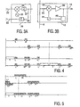
- the channels L* and H*, ranging from 2250 to 3450 MHz, by subtracting the value of the frequency from the value of 4400 MHz. The order of the channels is inverted: H* is to the left of L*.
- the channels L** and H**, ranging from 5350 to 6550 MHz, by adding the value of their frequency to the value of 4400 MHz. These channels are not annoying, and, furthermore, they have every chance of being suppressed in a natural way, because the passband of the amplifiers is limited.
Claims (10)
- A method of increasing the capacity expressed in a number of channels of a video communication signal distribution network in which a first set of video communication channels received by satellite (1) is converted into a predetermined frequency band in order to be delivered by a distribution cable (11) and used by at least one user apparatus (18) capable of using channels in a predetermined frequency band,
characterized in that at least a second set of video communication channels received by satellite (2) is converted into a frequency band situated completely above said predetermined frequency band in order to be distributed by the same distribution cable (11) as said first set of video communication channels, and in that for use in a user apparatus said second set of video communication channels is restored in said predetermined frequency band. - A method as claimed in Claim 1, characterized in that for the second set of converted channels, a frequency band is used having the same bandwidth as for the first set.
- A method as claimed in Claim 1, characterized in that a gap is left open between the frequency band of the second set of converted channels and the frequency band of the first set of converted channels.
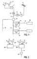
- A video communication signal distribution network comprising a distribution cable (11), at least one signal tapping element (12, 15) for supplying, from the cable, signals to at least one user apparatus (18) capable of using channels in a predetermined frequency band, at least one converter (LNB) delivering by said cable, in said predetermined frequency band, a first set of video communication channels received by satellite (1),
characterized in that it comprises at least a frequency translation module (LNB, 7) for translating at least a second set of video communication channels received by satellite, into a frequency band situated completely above said predetermined frequency band, said second set of video communication channel being distributed by said cable (11) with said first set of video communication channels, said tapping element comprising a converter module (13) for restoring said second set of video communication channels in said predetermined band, and a switch (14) for connecting said user apparatus either directly to the cable or to said converter module upon user request. - A video communication network as claimed in Claim 4, characterized in that a gap of at least 100 MHz is provided between the frequency band of the first set of converted channels and the frequency band of the second set of converted channels.
- A video communication network head-end comprising at least one satellite television broadcast converter (LNB) for converting a first set of video communication channels received by satellite (1) into a predetermined frequency band, for delivering said first set of video communication channel by a distribution cable (11) to at least one user apparatus (18) capable of using channels in said predetermined frequency band,
characterized in that it further comprises a frequency translation module (LNB, 7) for translating at least a second set of video communication channels received by satellite (2) into a frequency band situated completely above said predetermined frequency band in order to distribute said first and second video communication channels by the same cable (11). - A video communication network head-end as claimed in Claim 6, characterized in that the difference between the frequency band of the first set of converted channels and the frequency band of the second set of converted channels is at least 100 MHz.
- A signal tapping element (12, 15) for supplying, from a distribution cable (11), a first set of video communication channels received by satellite (1) and converted into a predetermined frequency band, to at least one user apparatus (18) capable of using channels in said predetermined frequency band,
characterized in that, at least a second set of video communication channels received by satellite (2) being translated to a frequency band situated completely above said predetermined frequency band in order to be distributed by said cable (11) with said first set of video communication channels, said tapping element comprises a converter module (13) for restoring said second set of video communication channels in said predetermined band, and a switch (14) for connecting said user apparatus either directly to said cable or to said converter module upon user request. - A signal tapping element (12, 15) as claimed in claim 8, characterized in that the translation of said second set of video communication channels is at least equal to 1300 MHZ.
- A signal tapping element (12, 15) as claimed in claim 8, characterized in that said switch is controlled either by the value of a continuous control voltage of 14 volt or 18 volt, or by the presence or absence of a 22kHz alternative voltage.
Applications Claiming Priority (3)
| Application Number | Priority Date | Filing Date | Title |
|---|---|---|---|
| FR9607634 | 1996-06-19 | ||
| FR9607634 | 1996-06-19 | ||
| PCT/IB1997/000664 WO1997049240A1 (en) | 1996-06-19 | 1997-06-09 | Video communication network |
Publications (2)
| Publication Number | Publication Date |
|---|---|
| EP0845189A1 EP0845189A1 (en) | 1998-06-03 |
| EP0845189B1 true EP0845189B1 (en) | 2003-09-17 |
Family
ID=9493219
Family Applications (1)
| Application Number | Title | Priority Date | Filing Date |
|---|---|---|---|
| EP97923282A Expired - Lifetime EP0845189B1 (en) | 1996-06-19 | 1997-06-09 | Video communication network |
Country Status (4)
| Country | Link |
|---|---|
| EP (1) | EP0845189B1 (en) |
| JP (1) | JPH11511937A (en) |
| DE (1) | DE69724916T2 (en) |
| WO (1) | WO1997049240A1 (en) |
Families Citing this family (6)
| Publication number | Priority date | Publication date | Assignee | Title |
|---|---|---|---|---|
| DE19747447A1 (en) * | 1997-10-28 | 1999-04-29 | Cit Alcatel | Device for merging and amplifying two broadband signals |
| DE19749120C2 (en) * | 1997-11-06 | 2002-07-18 | Kathrein Werke Kg | Satellite reception system and associated method for operating an antenna reception system |
| IT1299476B1 (en) * | 1998-05-25 | 2000-03-16 | Itel S P A | SYSTEM FOR COMBINED SIGNAL MANAGEMENT |
| US6600730B1 (en) * | 1998-08-20 | 2003-07-29 | Hughes Electronics Corporation | System for distribution of satellite signals from separate multiple satellites on a single cable line |
| EP1030522A1 (en) * | 1999-02-16 | 2000-08-23 | Koninklijke Philips Electronics N.V. | Method for transmitting upstream signals to a satellite from a video communication signals distribution network |
| EP1574084B1 (en) | 2002-12-11 | 2010-02-17 | R.F. Magic Inc. | Nxm crosspoint switch with band translation |
Family Cites Families (3)
| Publication number | Priority date | Publication date | Assignee | Title |
|---|---|---|---|---|
| FR2662895B1 (en) * | 1990-05-29 | 1992-08-28 | Telediffusion Fse | INSTALLATION FOR DISTRIBUTING BROADCASTING PROGRAMS WITH A CABLE NETWORK. |
| FR2680935B1 (en) * | 1991-08-30 | 1996-08-09 | Telediffusion Fse | WIRELESS NETWORK INSTALLATION FOR DISTRIBUTING AUDIOVISUAL PROGRAMS AND DIGITAL COMMUNICATION WITH A DIGITAL DATA BRIDGE. |
| EP0583830A1 (en) * | 1992-08-19 | 1994-02-23 | Philips Electronique Grand Public | Box for connecting to a distribution system of television signals and distribution system with selecting means |
-
1997
- 1997-06-09 DE DE69724916T patent/DE69724916T2/en not_active Expired - Fee Related
- 1997-06-09 JP JP10502593A patent/JPH11511937A/en not_active Withdrawn
- 1997-06-09 WO PCT/IB1997/000664 patent/WO1997049240A1/en active IP Right Grant
- 1997-06-09 EP EP97923282A patent/EP0845189B1/en not_active Expired - Lifetime
Also Published As
| Publication number | Publication date |
|---|---|
| DE69724916T2 (en) | 2004-07-15 |
| DE69724916D1 (en) | 2003-10-23 |
| WO1997049240A1 (en) | 1997-12-24 |
| JPH11511937A (en) | 1999-10-12 |
| EP0845189A1 (en) | 1998-06-03 |
Similar Documents
| Publication | Publication Date | Title |
|---|---|---|
| US5905941A (en) | Television signal cable distribution installation | |
| US5428404A (en) | Apparatus for method for selectively demodulating and remodulating alternate channels of a television broadcast | |
| USRE39202E1 (en) | Digital video converter box for subscriber/home with multiple television sets | |
| US5742680A (en) | Set top box for receiving and decryption and descrambling a plurality of satellite television signals | |
| US5412720A (en) | Interactive home information system | |
| AU670830B2 (en) | TV set-top converter | |
| US4603349A (en) | Cable television system with stereo sound reproduction | |
| EP1347644B1 (en) | Satellite signal distribution systems | |
| US8132214B2 (en) | Low noise block converter feedhorn | |
| GB2256115A (en) | Switched cable television networks. | |
| CA2270429A1 (en) | Direct broadcast satellite system for multiple dwelling units | |
| JP2001359068A (en) | Signal interface for two-directional communication unit | |
| MXPA96006588A (en) | Receptor apparatus, receiving method and termi unit | |
| US4586081A (en) | Method and apparatus for secure audio channel transmission in a CATV system | |
| EP0845189B1 (en) | Video communication network | |
| GB2283875A (en) | Terrestrial television broadcast system converter | |
| JP2001231033A (en) | Community reception system and frequency converter for terminal of the system | |
| RU2212115C2 (en) | Optimized system for distributing signals of television and telecommunication services from peripheral center to subscribers' terminals | |
| US5386226A (en) | Connection unit for a television signal distribution system | |
| US5532733A (en) | Remodulation of a cable box output signal to a UHF channel | |
| JPH0453103Y2 (en) | ||
| JPH09168104A (en) | Common reception facility | |
| RU2012142C1 (en) | Information transmitter-receiver system | |
| EP2680465B1 (en) | Video and/or audio data distribution system | |
| JPH10257410A (en) | Satellite reception system and power unit |
Legal Events
| Date | Code | Title | Description |
|---|---|---|---|
| PUAI | Public reference made under article 153(3) epc to a published international application that has entered the european phase |
Free format text: ORIGINAL CODE: 0009012 |
|
| AK | Designated contracting states |
Kind code of ref document: A1 Designated state(s): DE DK ES FI FR GB IT |
|
| RAP3 | Party data changed (applicant data changed or rights of an application transferred) |
Owner name: KONINKLIJKE PHILIPS ELECTRONICS N.V. |
|
| 17P | Request for examination filed |
Effective date: 19980624 |
|
| 17Q | First examination report despatched |
Effective date: 20010917 |
|
| GRAH | Despatch of communication of intention to grant a patent |
Free format text: ORIGINAL CODE: EPIDOS IGRA |
|
| GRAS | Grant fee paid |
Free format text: ORIGINAL CODE: EPIDOSNIGR3 |
|
| GRAA | (expected) grant |
Free format text: ORIGINAL CODE: 0009210 |
|
| AK | Designated contracting states |
Kind code of ref document: B1 Designated state(s): DE DK ES FI FR GB IT |
|
| PG25 | Lapsed in a contracting state [announced via postgrant information from national office to epo] |
Ref country code: IT Free format text: LAPSE BECAUSE OF FAILURE TO SUBMIT A TRANSLATION OF THE DESCRIPTION OR TO PAY THE FEE WITHIN THE PRE;WARNING: LAPSES OF ITALIAN PATENTS WITH EFFECTIVE DATE BEFORE 2007 MAY HAVE OCCURRED AT ANY TIME BEFORE 2007. THE CORRECT EFFECTIVE DATE MAY BE DIFFERENT FROM THE ONE RECORDED.SCRIBED TIME-LIMIT Effective date: 20030917 Ref country code: FI Free format text: LAPSE BECAUSE OF FAILURE TO SUBMIT A TRANSLATION OF THE DESCRIPTION OR TO PAY THE FEE WITHIN THE PRESCRIBED TIME-LIMIT Effective date: 20030917 |
|
| REG | Reference to a national code |
Ref country code: GB Ref legal event code: FG4D |
|
| REF | Corresponds to: |
Ref document number: 69724916 Country of ref document: DE Date of ref document: 20031023 Kind code of ref document: P |
|
| PG25 | Lapsed in a contracting state [announced via postgrant information from national office to epo] |
Ref country code: DK Free format text: LAPSE BECAUSE OF FAILURE TO SUBMIT A TRANSLATION OF THE DESCRIPTION OR TO PAY THE FEE WITHIN THE PRESCRIBED TIME-LIMIT Effective date: 20031217 |
|
| PG25 | Lapsed in a contracting state [announced via postgrant information from national office to epo] |
Ref country code: ES Free format text: LAPSE BECAUSE OF FAILURE TO SUBMIT A TRANSLATION OF THE DESCRIPTION OR TO PAY THE FEE WITHIN THE PRESCRIBED TIME-LIMIT Effective date: 20031228 |
|
| ET | Fr: translation filed | ||
| PGFP | Annual fee paid to national office [announced via postgrant information from national office to epo] |
Ref country code: GB Payment date: 20040629 Year of fee payment: 8 |
|
| PLBE | No opposition filed within time limit |
Free format text: ORIGINAL CODE: 0009261 |
|
| STAA | Information on the status of an ep patent application or granted ep patent |
Free format text: STATUS: NO OPPOSITION FILED WITHIN TIME LIMIT |
|
| PGFP | Annual fee paid to national office [announced via postgrant information from national office to epo] |
Ref country code: DE Payment date: 20040813 Year of fee payment: 8 |
|
| 26N | No opposition filed |
Effective date: 20040618 |
|
| REG | Reference to a national code |
Ref country code: GB Ref legal event code: 746 Effective date: 20050518 |
|
| PG25 | Lapsed in a contracting state [announced via postgrant information from national office to epo] |
Ref country code: GB Free format text: LAPSE BECAUSE OF NON-PAYMENT OF DUE FEES Effective date: 20050609 |
|
| PGFP | Annual fee paid to national office [announced via postgrant information from national office to epo] |
Ref country code: FR Payment date: 20050628 Year of fee payment: 9 |
|
| PG25 | Lapsed in a contracting state [announced via postgrant information from national office to epo] |
Ref country code: DE Free format text: LAPSE BECAUSE OF NON-PAYMENT OF DUE FEES Effective date: 20060103 |
|
| GBPC | Gb: european patent ceased through non-payment of renewal fee |
Effective date: 20050609 |
|
| REG | Reference to a national code |
Ref country code: FR Ref legal event code: ST Effective date: 20070228 |
|
| PG25 | Lapsed in a contracting state [announced via postgrant information from national office to epo] |
Ref country code: FR Free format text: LAPSE BECAUSE OF NON-PAYMENT OF DUE FEES Effective date: 20060630 |