EP0844359A2 - Draft strips for doors - Google Patents
Draft strips for doors Download PDFInfo
- Publication number
- EP0844359A2 EP0844359A2 EP97830523A EP97830523A EP0844359A2 EP 0844359 A2 EP0844359 A2 EP 0844359A2 EP 97830523 A EP97830523 A EP 97830523A EP 97830523 A EP97830523 A EP 97830523A EP 0844359 A2 EP0844359 A2 EP 0844359A2
- Authority
- EP
- European Patent Office
- Prior art keywords
- movable part
- slide
- brace
- attachment
- support section
- Prior art date
- Legal status (The legal status is an assumption and is not a legal conclusion. Google has not performed a legal analysis and makes no representation as to the accuracy of the status listed.)
- Granted
Links
Images


Classifications
-
- E—FIXED CONSTRUCTIONS
- E06—DOORS, WINDOWS, SHUTTERS, OR ROLLER BLINDS IN GENERAL; LADDERS
- E06B—FIXED OR MOVABLE CLOSURES FOR OPENINGS IN BUILDINGS, VEHICLES, FENCES OR LIKE ENCLOSURES IN GENERAL, e.g. DOORS, WINDOWS, BLINDS, GATES
- E06B7/00—Special arrangements or measures in connection with doors or windows
- E06B7/16—Sealing arrangements on wings or parts co-operating with the wings
- E06B7/18—Sealing arrangements on wings or parts co-operating with the wings by means of movable edgings, e.g. draught sealings additionally used for bolting, e.g. by spring force or with operating lever
- E06B7/20—Sealing arrangements on wings or parts co-operating with the wings by means of movable edgings, e.g. draught sealings additionally used for bolting, e.g. by spring force or with operating lever automatically withdrawn when the wing is opened, e.g. by means of magnetic attraction, a pin or an inclined surface, especially for sills
- E06B7/215—Sealing arrangements on wings or parts co-operating with the wings by means of movable edgings, e.g. draught sealings additionally used for bolting, e.g. by spring force or with operating lever automatically withdrawn when the wing is opened, e.g. by means of magnetic attraction, a pin or an inclined surface, especially for sills with sealing strip being moved to a retracted position by elastic means, e.g. springs
Abstract
Description
- a channel-like section to be fixed in a seat at the base of the leaf of a door,
- a movable part that is mounted in the fixed channel-like section, which can be moved in height, towards and away from the floor under the door;
- at least one weather strip supported by the movable part and intended to rest on the ground when the part is lowered;
- a pushing element at at least one end of the movable part intended to be engaged with a corresponding doorjamb to bring about the lowering of the movable part and the resting on the ground of the weather strip when the door is closed; and
- at least one means to adjust the position and the action of the movable part.
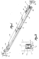
In the drawings:
- a
first attachment slide 21, which is inserted and slides in thetrack 11b of thesupport section 11, and an adjustingslide 22, which is inserted and slides in the channel-like seat 13' in themovable part 13; - a
first brace 19 and afirst return spring 20, which are connected, on the one hand, to thefirst attachment slide 21, and on the other hand, to the adjustingslide 22; - a
second attachment slide 25, which is also inserted and slides in thetrack 11b of thesupport section 11, and astop slide 26, which slides in themovable part 13 and is engaged against a nib 13'' on the bottom of the part in order to limit its movements; and - a
second brace 23 and asecond return spring 24, which are connected, on the one hand, to the second attachment slide 25, and on the other hand, to the stop slide 26.
Claims (20)
- A draft strip device for doors, the device comprising:a channel-like support section to be fixed at said base of a door;a movable part mounted in said channel-like support section, which can be moved in height towards and away from said floor under said door;at least one weather strip seal supported by said movable part and intended to rest on ground when said movable part is lowered;a pushing element at one end of said movable part, said pushing element being intended to be engaged with a respective doorjamb to bring about said lowering of said movable part and said resting on the ground of said weather strip when said door is closed;at least one said adjusting element to adjust a position and an action of said movable part;a first, rigid or spring-actuated brace and at least a second, rigid or spring-actuated brace, which are spaced apart from one another said movable part being supported and being articulated with said support section in at least two parts, which are separated by said first, rigid or spring-actuated brace and said second, rigid or spring-actuated brace;a first attachment slide and an adjusting slide, said first brace being connected at its ends to said first attachment slide, which is inserted and can be moved longitudinally in said support section, and to said adjusting slide, which is inserted and can be moved longitudinally in said movable part with said weather strip seal;a second attachment slide;a stop slide;a second brace connected at its ends to said second attachment slide, which is inserted and can be moved longitudinally in said support section, and to said stop slide, which is arranged and can be moved within certain limits in said longitudinal direction in said movable part with said seal, said first and second attachment slides being combined by an intermediate connecting section, which can be moved longitudinally `with said slides in said support section, said pushing element being connected to said first attachment slide in an adjustable manner, said adjusting element being connected to said adjusting slide; andrabbet means, which is intended to interact with locking means fixed in said support section, said rabbet means being fixed in said movable part in order to bring about a lowering of said movable part with said seal in response to a force applied to said pushing element.
- A draft strip device for doors, the device comprising:a channel-like support section to be fixed at said base of a door;a movable part mounted in said channel-like support section, which can be moved in height towards and away from said floor under said door;at least one weather strip seal supported by said movable part and intended to rest on ground when said movable part is lowered;a pushing element at one end of said movable part, said pushing element being intended to be engaged with a respective doorjamb to bring about said lowering of said movable part and said resting on the ground of said weather strip when said door is closed;at least one said adjusting element to adjust a position and an action of said movable part;a first, rigid or spring-actuated brace and at least a second, rigid or spring-actuated brace, which are spaced apart from one another said movable part being supported and being articulated with said support section in at least two parts, which are separated by said first, rigid or spring-actuated brace and said second, rigid or spring-actuated brace;a first attachment slide and an adjusting slide, said first brace being connected at its ends to said first attachment slide, which is inserted and can be moved longitudinally in said support section, and to said adjusting slide, which is inserted and can be moved longitudinally in said movable part with said weather strip seal;a second attachment slide;a stop slide;a second brace connected at its ends to said second attachment slide, which is inserted and can be moved longitudinally in said support section, and to said stop slide, which is arranged and can be moved within certain limits in said longitudinal direction in said movable part with said seal, said first and second attachment slides being combined by an intermediate connecting section, which can be moved longitudinally with said slides in said support section, said pushing element being connected to said first attachment slide in an adjustable manner, said adjusting element being connected to said adjusting slide;a third, rigid brace connecting said movable part to said support section, with said third brace having a foot, which is hinged to said stop slide, and a head that is movably coupled to said second attachment slide and resting, in said direction of said control force on said pushing element, against locking nibs which are integral with said fixed support section, and said third brace extends into a crevice made in said second attachment slide, and said head is forced in a longitudinal guide inside said support section.
- A device in accordance with claim 1, wherein said first and second braces are rigid and a spring is associated with each of said first and second braces for said return of said movable part into a raised, resting position.
- A device in accordance with claim 1, wherein said first and second braces are spring-actuated with ends hinged to said corresponding slides.
- A device in accordance with claim 3, wherein said first and second braces are oriented in a same direction, are essentially parallel to one another and are turned in a direction of a control force on said pushing element from said corresponding attachment slides towards said adjusting slide and said stop slide, respectively.
- A device in accordance with claim 2, wherein said third brace is rigid or spring-actuated with its ends hinged to said corresponding slides.
- A device in accordance with claim 1, wherein said attachment slides and said connecting part are coupled for providing longitudinal movement of one in relation to said other.
- A device in accordance with claim 2, wherein said first and second braces are oriented in a same direction, are essentially parallel to one another and are turned in a direction of a control force on said pushing element from said corresponding attachment slides towards said adjusting slide and said stop slide, respectively, and in which said third brace is oriented in a direction that is opposite that of said first and second braces from its head towards its foot.
- A device in accordance with claim 2, wherein said third brace is arranged between said first and second braces or on another side of said second brace close to an end of the device, which is said furthest from said pushing element.
- A device in accordance with claims 1, wherein said stop slide, to which said foot of said third brace is connected, has an end shoulder, which is intended to rest against a locking nib on said bottom of said movable part in order to limit said movement of said slide in one direction, and said movement in said opposite direction is limited by a hook at an end of a shank that is integral with said slide and also interacts with said nib.
- A device in accordance with claim 1, wherein said pushing element is screwed down and is adjustable on a threaded shank, which is integral with said first attachment slide.
- A device in accordance with claim 1, wherein said adjusting part is a threaded bush, which is mounted rotatably and without translatory movement on a support that is locked in said movable part and is screwed to a threaded shank, which is fixed to said adjusting slide.
- A device in accordance with claim 1, wherein lateral weather strips are provided between said sides of said movable part and said fixed support section, and in which said weather strips are provided against doorjambs at said opposite ends of the device.
- A device in accordance with claim 2, wherein said first and second braces are rigid and a spring is associated with each of said first and second braces for said return of said movable part into a raised, resting position.
- A device in accordance with claim 2, wherein said first and second braces are spring-actuated with ends hinged to said corresponding slides.
- A device in accordance with claim 14, wherein said first and second braces are oriented in a same direction, are essentially parallel to one another and are turned in a direction of a control force on said pushing element from said corresponding attachment slides towards said adjusting slide and said stop slide, respectively.
- A device in accordance with claim 2, wherein said attachment slides and said connecting part are coupled for providing longitudinal movement of one in relation to said other.
- A device in accordance with claims 2, wherein said stop slide, to which said foot of said third brace is connected, has an end shoulder, which is intended to rest against a locking nib on said bottom of said movable part in order to limit said movement of said slide in one direction, and said movement in said opposite direction is limited by a hook at an end of a shank that is integral with said slide and also interacts with said nib.
- A device in accordance with claim 2, wherein said adjusting part is a threaded bush, which is mounted rotatably and without translatory movement on a support that is locked in said movable part and is screwed to a threaded shank, which is fixed to said adjusting slide.
- A device in accordance with claim 2, wherein lateral weather strips are provided between said sides of said movable part and said fixed support section, and in which said weather strips are provided against doorjambs at said opposite ends of the device.
Priority Applications (1)
| Application Number | Priority Date | Filing Date | Title |
|---|---|---|---|
| SI9730540T SI0844359T1 (en) | 1996-10-23 | 1997-10-17 | Draft strips for doors |
Applications Claiming Priority (2)
| Application Number | Priority Date | Filing Date | Title |
|---|---|---|---|
| IT96BS000084A IT1288251B1 (en) | 1996-10-23 | 1996-10-23 | COOLING DEVICE FOR DOORS |
| ITBS960084 | 1996-10-23 |
Publications (3)
| Publication Number | Publication Date |
|---|---|
| EP0844359A2 true EP0844359A2 (en) | 1998-05-27 |
| EP0844359A3 EP0844359A3 (en) | 1999-08-04 |
| EP0844359B1 EP0844359B1 (en) | 2003-04-02 |
Family
ID=11345833
Family Applications (1)
| Application Number | Title | Priority Date | Filing Date |
|---|---|---|---|
| EP97830523A Expired - Lifetime EP0844359B1 (en) | 1996-10-23 | 1997-10-17 | Draft strips for doors |
Country Status (9)
| Country | Link |
|---|---|
| US (1) | US6082047A (en) |
| EP (1) | EP0844359B1 (en) |
| AT (1) | ATE236338T1 (en) |
| DE (1) | DE69720377T2 (en) |
| DK (1) | DK0844359T3 (en) |
| ES (1) | ES2195107T3 (en) |
| IT (1) | IT1288251B1 (en) |
| PT (1) | PT844359E (en) |
| SI (1) | SI0844359T1 (en) |
Cited By (6)
| Publication number | Priority date | Publication date | Assignee | Title |
|---|---|---|---|---|
| ES2174664A1 (en) * | 1999-03-02 | 2002-11-01 | Carranza Luis Muller | Elevated automatically descending draft excluder for lower edge of door jambs, has two end sections each connected to side of door jamb and third laid out in sliding fashion to cover separation between two fixed end sections |
| EP1365099A2 (en) * | 2002-05-24 | 2003-11-26 | Comaglio S.r.l. | Reversible draught excluding device for doors |
| WO2012032295A1 (en) * | 2010-09-07 | 2012-03-15 | Rbp Associates Limited Et Al | Automatic door bottom drop-down seal |
| ITBS20130043A1 (en) * | 2013-04-02 | 2014-10-03 | Comaglio S R L | LENGTH ADJUSTABLE FROST COOLING DEVICE |
| US9885211B2 (en) | 2012-08-30 | 2018-02-06 | Rbp Associates Limited | Door seal |
| WO2020037822A1 (en) * | 2018-08-20 | 2020-02-27 | 深圳市大疆创新科技有限公司 | Door bottom sealing device and door |
Families Citing this family (38)
| Publication number | Priority date | Publication date | Assignee | Title |
|---|---|---|---|---|
| ES2272233T3 (en) * | 1999-03-02 | 2007-05-01 | Luis Muller Carranza | BURLETE. |
| US7260915B2 (en) * | 2003-04-15 | 2007-08-28 | Firma F. Athmer | Door seal device |
| US6871448B1 (en) | 2003-10-20 | 2005-03-29 | C. Walter Kline | Apparatus moving with a sliding door to provide an unobstructed passageway and to seal a notch within a watertight barrier |
| DE102006007511A1 (en) * | 2005-06-14 | 2006-12-21 | Wilfried Boldt | Rail-guided mobile wall element |
| US8074400B2 (en) * | 2006-06-20 | 2011-12-13 | Secura-Seal Technologies Llc | Combined modular sealing systems and seal activation system for door/window |
| US8627606B2 (en) | 2005-12-30 | 2014-01-14 | Tyto Life LLC | Combined sealing system for garage door |
| US7685776B2 (en) * | 2005-12-30 | 2010-03-30 | Speyer Door And Window, Inc. | Sealing system for sliding door/window |
| US7624539B2 (en) | 2005-12-30 | 2009-12-01 | Speyer Door And Window, Inc. | Combined sealing systems for pivoting door/window |
| US8109037B2 (en) | 2005-12-30 | 2012-02-07 | Secura-Seal Technologies Llc | Active sealing system for single-hung door/window |
| US7685775B2 (en) | 2005-12-30 | 2010-03-30 | Speyer Door And Window, Inc. | Combined sealing systems for sliding door/window |
| US7627987B2 (en) * | 2005-12-30 | 2009-12-08 | Speyer Door And Window, Inc. | Combined sealing system and seal activation system for door |
| US8925249B2 (en) | 2006-06-20 | 2015-01-06 | Tyto Life LLC | Active sealing and securing systems for door/window |
| US7707773B2 (en) | 2005-12-30 | 2010-05-04 | Speyer Door And Window, Inc. | Seal activation system positioned within panel for door/window |
| US8336258B2 (en) | 2005-12-30 | 2012-12-25 | Secura-Seal Technologies Llc | Self-driving combination sealing system for single-hung door/window |
| US8091282B2 (en) * | 2005-12-30 | 2012-01-10 | Secura-Seal Technologies Llc | Combined sealing system and seal activation system for door/window |
| US8539717B2 (en) | 2005-12-30 | 2013-09-24 | Secura-Seal Technologies Llc | Electronic control for door/window |
| US7685774B2 (en) * | 2005-12-30 | 2010-03-30 | Speyer Door And Window, Inc. | Closing system for sealing system of sliding door/window |
| US7665245B2 (en) * | 2005-12-30 | 2010-02-23 | Speyer Door And Window, Inc. | Sealing system positioned within frame for door/window |
| US8074399B2 (en) | 2006-06-20 | 2011-12-13 | Secura-Seal Technologies Llc | Sealing system modules for door/window |
| DE202007016379U1 (en) * | 2007-11-21 | 2009-04-09 | F. Athmer Ohg | Lowerable bottom seal with at least partially soft trigger element |
| AU2009260245B2 (en) * | 2008-06-17 | 2015-05-07 | John B . Higman And Valorie J . Higman; Trustees Of The Higman Family Trust U/D/T As Amended And Restated On December 22, 2006. | Automatically sealing door and door system |
| US8468746B2 (en) | 2008-09-30 | 2013-06-25 | Tyto Life LLC | Sealing systems for garage door |
| US8484899B2 (en) | 2008-09-30 | 2013-07-16 | Tyto Life LLC | Driving and driven sealing systems for single-hung door/window |
| US8516756B2 (en) | 2009-04-27 | 2013-08-27 | Secura-Seal Technologies Llc | Door panel with thermal break |
| US8381448B2 (en) * | 2010-05-04 | 2013-02-26 | Special-Lite, Inc. | Adjustable door sweep |
| US8336257B2 (en) * | 2010-07-16 | 2012-12-25 | Railquip Enterprises Inc. | Telescoping floor seal for vertically displaceable partition |
| US9217277B2 (en) | 2010-10-25 | 2015-12-22 | John B. Higman and Valorie J. Higman | Door drainage system |
| WO2014029877A1 (en) * | 2012-08-23 | 2014-02-27 | Planet Gdz Ag | Door seal with two sealing planes |
| US8955271B2 (en) | 2012-09-17 | 2015-02-17 | Steelcase Inc. | Sliding door assembly |
| US20150152679A1 (en) * | 2013-11-29 | 2015-06-04 | ETS-Lindgren Inc. | Manual-automatic rf sealing system |
| USD738532S1 (en) * | 2013-12-19 | 2015-09-08 | Hsing-Hua KUAN | Electric threshold |
| CN103883234A (en) * | 2014-03-11 | 2014-06-25 | 江苏海陆科技股份有限公司 | Barrier-free high-sound-insulating fireproof door for ship |
| JP6655314B2 (en) * | 2015-07-21 | 2020-02-26 | 株式会社ベスト | Door shutter device |
| US10024100B2 (en) * | 2016-04-26 | 2018-07-17 | Cmech (Guangzhou) Ltd. | Magnetically actuated door seal |
| US20200284087A1 (en) * | 2016-05-06 | 2020-09-10 | Oscar RODRIGUEZ RODRIGUEZ | Device for sealing below doors |
| WO2018165129A1 (en) * | 2017-03-09 | 2018-09-13 | Conway Matthew B | Window shade device |
| US20220268094A1 (en) * | 2021-02-24 | 2022-08-25 | Baron Carleton | E-auto door bottom |
| US11932457B1 (en) | 2023-06-21 | 2024-03-19 | William Kasdon | Container closure systems |
Citations (4)
| Publication number | Priority date | Publication date | Assignee | Title |
|---|---|---|---|---|
| GB293196A (en) * | 1927-07-05 | 1928-07-05 | Harry William Aves | Draught excluder for the bottoms of doors, windows, and the like |
| US4089136A (en) * | 1976-06-07 | 1978-05-16 | Catuma Pty. Ltd. | Weather excluder |
| US4805345A (en) * | 1987-07-10 | 1989-02-21 | Nankai Kogyo Kabushiki Kaisha | Sealing device for a door |
| GB2304776A (en) * | 1995-09-06 | 1997-03-26 | Raven Products Pty Ltd | Retractable door seal |
Family Cites Families (14)
| Publication number | Priority date | Publication date | Assignee | Title |
|---|---|---|---|---|
| US813411A (en) * | 1904-10-14 | 1906-02-27 | Clarence M Eveleth | Weather-strip. |
| US813268A (en) * | 1905-07-31 | 1906-02-20 | Lewis W Woodburn | Weather-strip. |
| GB274376A (en) * | 1927-02-26 | 1927-07-21 | Voor Controle Associate En Tru | Adjustable draught, dust and weather excluder for doors and the like |
| GB319116A (en) * | 1928-08-18 | 1929-09-19 | Richard Holmes | Improvements appertaining to weather-bars or draught excluders for doors and hinged windows |
| US2250821A (en) * | 1939-05-22 | 1941-07-29 | Harry A Bedol | Weather strip |
| GB686612A (en) * | 1950-07-14 | 1953-01-28 | Colin Neville Wheildon | An improved draught excluder |
| DE846785C (en) * | 1950-08-26 | 1952-08-18 | Otto Starke | Sealing device for lower door edges |
| CH285700A (en) * | 1950-12-15 | 1952-09-30 | Allger Jos | Sealing device on threshold-free doors. |
| US2820261A (en) * | 1956-06-14 | 1958-01-21 | Kenneth B Thompson | Retractable seal for a slidable closure member |
| US3072977A (en) * | 1958-12-01 | 1963-01-15 | Burda Josef | Draft excluding strip for door |
| DE1185505B (en) * | 1959-02-17 | 1965-01-14 | Athmer Fa F | Device for the automatic closing of a door leaf and sealing of the floor gap by means of a sealing strip that is forced to move |
| DE1181389B (en) * | 1959-07-22 | 1964-11-12 | Athmer Fa F | Sealing device for doors |
| AT224878B (en) * | 1960-09-17 | 1962-12-10 | Andreas Gragin-Kalser | Sealing device for doors or the like. |
| US5467559A (en) * | 1994-07-19 | 1995-11-21 | Modernfold, Incorporated | Electrically operated drop seal for pass doors in operable walls |
-
1996
- 1996-10-23 IT IT96BS000084A patent/IT1288251B1/en active IP Right Grant
-
1997
- 1997-10-17 SI SI9730540T patent/SI0844359T1/en unknown
- 1997-10-17 AT AT97830523T patent/ATE236338T1/en active
- 1997-10-17 ES ES97830523T patent/ES2195107T3/en not_active Expired - Lifetime
- 1997-10-17 PT PT97830523T patent/PT844359E/en unknown
- 1997-10-17 EP EP97830523A patent/EP0844359B1/en not_active Expired - Lifetime
- 1997-10-17 DE DE69720377T patent/DE69720377T2/en not_active Expired - Lifetime
- 1997-10-17 DK DK97830523T patent/DK0844359T3/en active
- 1997-10-22 US US08/955,496 patent/US6082047A/en not_active Expired - Fee Related
Patent Citations (4)
| Publication number | Priority date | Publication date | Assignee | Title |
|---|---|---|---|---|
| GB293196A (en) * | 1927-07-05 | 1928-07-05 | Harry William Aves | Draught excluder for the bottoms of doors, windows, and the like |
| US4089136A (en) * | 1976-06-07 | 1978-05-16 | Catuma Pty. Ltd. | Weather excluder |
| US4805345A (en) * | 1987-07-10 | 1989-02-21 | Nankai Kogyo Kabushiki Kaisha | Sealing device for a door |
| GB2304776A (en) * | 1995-09-06 | 1997-03-26 | Raven Products Pty Ltd | Retractable door seal |
Cited By (8)
| Publication number | Priority date | Publication date | Assignee | Title |
|---|---|---|---|---|
| ES2174664A1 (en) * | 1999-03-02 | 2002-11-01 | Carranza Luis Muller | Elevated automatically descending draft excluder for lower edge of door jambs, has two end sections each connected to side of door jamb and third laid out in sliding fashion to cover separation between two fixed end sections |
| EP1365099A2 (en) * | 2002-05-24 | 2003-11-26 | Comaglio S.r.l. | Reversible draught excluding device for doors |
| EP1365099A3 (en) * | 2002-05-24 | 2004-03-24 | Comaglio S.r.l. | Reversible draught excluding device for doors |
| WO2012032295A1 (en) * | 2010-09-07 | 2012-03-15 | Rbp Associates Limited Et Al | Automatic door bottom drop-down seal |
| US8925250B2 (en) | 2010-09-07 | 2015-01-06 | Rbp Associates Limited | Automatic door bottom drop-down seal |
| US9885211B2 (en) | 2012-08-30 | 2018-02-06 | Rbp Associates Limited | Door seal |
| ITBS20130043A1 (en) * | 2013-04-02 | 2014-10-03 | Comaglio S R L | LENGTH ADJUSTABLE FROST COOLING DEVICE |
| WO2020037822A1 (en) * | 2018-08-20 | 2020-02-27 | 深圳市大疆创新科技有限公司 | Door bottom sealing device and door |
Also Published As
| Publication number | Publication date |
|---|---|
| PT844359E (en) | 2003-08-29 |
| IT1288251B1 (en) | 1998-09-11 |
| SI0844359T1 (en) | 2003-10-31 |
| ES2195107T3 (en) | 2003-12-01 |
| ATE236338T1 (en) | 2003-04-15 |
| DE69720377T2 (en) | 2004-03-04 |
| EP0844359B1 (en) | 2003-04-02 |
| DE69720377D1 (en) | 2003-05-08 |
| EP0844359A3 (en) | 1999-08-04 |
| DK0844359T3 (en) | 2003-07-21 |
| US6082047A (en) | 2000-07-04 |
| ITBS960084A0 (en) | 1996-10-23 |
| ITBS960084A1 (en) | 1998-04-23 |
Similar Documents
| Publication | Publication Date | Title |
|---|---|---|
| EP0844359B1 (en) | Draft strips for doors | |
| US5244238A (en) | Locking mechanism for sash type windows | |
| CA2810599C (en) | Automatic door bottom drop-down seal | |
| US4208838A (en) | Latch hardware | |
| US3054152A (en) | Window unit | |
| US4928428A (en) | Lever-activated locking bar brace for a window or a door | |
| US7412800B2 (en) | Latching and anti-bow mechanism for a window | |
| US20180320437A1 (en) | Sealing unit for a sliding door | |
| CA2130052A1 (en) | Locking system for a double hung window | |
| CZ289954B6 (en) | Window, intended particularly for installation in an inclined roof surface | |
| CA2434348A1 (en) | Automatic door sweep | |
| US6722082B1 (en) | Window having a hinged weatherstrip | |
| EP2924224B2 (en) | Controllably operating draught excluder device | |
| US3023804A (en) | Articulated door construction | |
| EP2280143A2 (en) | An improved pivot window with at least one auxiliary opening device | |
| EP3042017B1 (en) | Weathertight window or door having at least one sliding wing | |
| US5185955A (en) | Sash windows | |
| CA2410112A1 (en) | Block and tackle sash balance brake assembly | |
| US2187459A (en) | Pressure seal for windows and doors | |
| GB2134167A (en) | Shower cubicle sealing door | |
| US10787849B1 (en) | Sash balance for vertical slider window | |
| CN210033030U (en) | Hollow sliding groove type door and window hinge | |
| EP2821575A2 (en) | An improved pivot window with at least one auxiliary opening device and check means | |
| US2937699A (en) | Folding door | |
| DE19650085A1 (en) | Bottom-corner bearing for hinging and tilting window or door |
Legal Events
| Date | Code | Title | Description |
|---|---|---|---|
| PUAI | Public reference made under article 153(3) epc to a published international application that has entered the european phase |
Free format text: ORIGINAL CODE: 0009012 |
|
| AK | Designated contracting states |
Kind code of ref document: A2 Designated state(s): AT BE CH DE DK ES FI FR GB GR IE IT LI LU MC NL PT SE |
|
| AX | Request for extension of the european patent |
Free format text: AL;LT;LV;RO;SI |
|
| PUAL | Search report despatched |
Free format text: ORIGINAL CODE: 0009013 |
|
| AK | Designated contracting states |
Kind code of ref document: A3 Designated state(s): AT BE CH DE DK ES FI FR GB GR IE IT LI LU MC NL PT SE |
|
| AX | Request for extension of the european patent |
Free format text: AL;LT;LV;RO;SI |
|
| 17P | Request for examination filed |
Effective date: 19991222 |
|
| AKX | Designation fees paid |
Free format text: AT BE CH DE DK ES FI FR GB GR IE IT LI LU MC NL PT SE |
|
| AXX | Extension fees paid |
Free format text: AL PAYMENT 19991222;LT PAYMENT 19991222;LV PAYMENT 19991222;RO PAYMENT 19991222;SI PAYMENT 19991222 |
|
| 17Q | First examination report despatched |
Effective date: 20011217 |
|
| GRAH | Despatch of communication of intention to grant a patent |
Free format text: ORIGINAL CODE: EPIDOS IGRA |
|
| GRAH | Despatch of communication of intention to grant a patent |
Free format text: ORIGINAL CODE: EPIDOS IGRA |
|
| GRAA | (expected) grant |
Free format text: ORIGINAL CODE: 0009210 |
|
| AK | Designated contracting states |
Designated state(s): AT BE CH DE DK ES FI FR GB GR IE IT LI LU MC NL PT SE |
|
| AX | Request for extension of the european patent |
Extension state: AL LT LV RO SI |
|
| REG | Reference to a national code |
Ref country code: GB Ref legal event code: FG4D |
|
| REG | Reference to a national code |
Ref country code: CH Ref legal event code: EP |
|
| REG | Reference to a national code |
Ref country code: IE Ref legal event code: FG4D |
|
| REF | Corresponds to: |
Ref document number: 69720377 Country of ref document: DE Date of ref document: 20030508 Kind code of ref document: P |
|
| RIN2 | Information on inventor provided after grant (corrected) |
Inventor name: VEZZOLA, CATERINA Inventor name: COMAGLIO, ALDO |
|
| REG | Reference to a national code |
Ref country code: GR Ref legal event code: EP Ref document number: 20030402381 Country of ref document: GR |
|
| REG | Reference to a national code |
Ref country code: DK Ref legal event code: T3 |
|
| REG | Reference to a national code |
Ref country code: SE Ref legal event code: TRGR |
|
| RAP2 | Party data changed (patent owner data changed or rights of a patent transferred) |
Owner name: COMAGLIO S.R.L. |
|
| REG | Reference to a national code |
Ref country code: CH Ref legal event code: NV Representative=s name: ISLER & PEDRAZZINI AG |
|
| NLT2 | Nl: modifications (of names), taken from the european patent patent bulletin |
Owner name: COMAGLIO S.R.L. |
|
| NLXE | Nl: other communications concerning ep-patents (part 3 heading xe) |
Free format text: PAT. BUL. 09/2003: CORR.: COMAGLIO S.R.L. |
|
| ET | Fr: translation filed | ||
| PLBE | No opposition filed within time limit |
Free format text: ORIGINAL CODE: 0009261 |
|
| STAA | Information on the status of an ep patent application or granted ep patent |
Free format text: STATUS: NO OPPOSITION FILED WITHIN TIME LIMIT |
|
| 26N | No opposition filed |
Effective date: 20040105 |
|
| REG | Reference to a national code |
Ref country code: SI Ref legal event code: IF |
|
| PGFP | Annual fee paid to national office [announced via postgrant information from national office to epo] |
Ref country code: CH Payment date: 20130830 Year of fee payment: 17 |
|
| PGFP | Annual fee paid to national office [announced via postgrant information from national office to epo] |
Ref country code: DK Payment date: 20131021 Year of fee payment: 17 |
|
| PGFP | Annual fee paid to national office [announced via postgrant information from national office to epo] |
Ref country code: MC Payment date: 20131015 Year of fee payment: 17 Ref country code: SE Payment date: 20131018 Year of fee payment: 17 |
|
| PGFP | Annual fee paid to national office [announced via postgrant information from national office to epo] |
Ref country code: GR Payment date: 20131021 Year of fee payment: 17 Ref country code: FI Payment date: 20131018 Year of fee payment: 17 |
|
| REG | Reference to a national code |
Ref country code: CH Ref legal event code: PCAR Free format text: NEW ADDRESS: VIA LUGANETTO 3, 6962 LUGANO (CH) |
|
| PG25 | Lapsed in a contracting state [announced via postgrant information from national office to epo] |
Ref country code: MC Free format text: LAPSE BECAUSE OF NON-PAYMENT OF DUE FEES Effective date: 20141031 |
|
| REG | Reference to a national code |
Ref country code: CH Ref legal event code: PL |
|
| REG | Reference to a national code |
Ref country code: SE Ref legal event code: EUG |
|
| REG | Reference to a national code |
Ref country code: GR Ref legal event code: ML Ref document number: 20030402381 Country of ref document: GR Effective date: 20150505 |
|
| PG25 | Lapsed in a contracting state [announced via postgrant information from national office to epo] |
Ref country code: FI Free format text: LAPSE BECAUSE OF NON-PAYMENT OF DUE FEES Effective date: 20141017 Ref country code: SE Free format text: LAPSE BECAUSE OF NON-PAYMENT OF DUE FEES Effective date: 20141018 Ref country code: CH Free format text: LAPSE BECAUSE OF NON-PAYMENT OF DUE FEES Effective date: 20141031 Ref country code: LI Free format text: LAPSE BECAUSE OF NON-PAYMENT OF DUE FEES Effective date: 20141031 |
|
| REG | Reference to a national code |
Ref country code: SI Ref legal event code: KO00 Effective date: 20150610 |
|
| REG | Reference to a national code |
Ref country code: DK Ref legal event code: EBP Effective date: 20141031 |
|
| PG25 | Lapsed in a contracting state [announced via postgrant information from national office to epo] |
Ref country code: GR Free format text: LAPSE BECAUSE OF NON-PAYMENT OF DUE FEES Effective date: 20150505 |
|
| PG25 | Lapsed in a contracting state [announced via postgrant information from national office to epo] |
Ref country code: DK Free format text: LAPSE BECAUSE OF NON-PAYMENT OF DUE FEES Effective date: 20141031 |
|
| REG | Reference to a national code |
Ref country code: FR Ref legal event code: PLFP Year of fee payment: 19 |
|
| REG | Reference to a national code |
Ref country code: FR Ref legal event code: PLFP Year of fee payment: 20 |
|
| PGFP | Annual fee paid to national office [announced via postgrant information from national office to epo] |
Ref country code: ES Payment date: 20160915 Year of fee payment: 20 Ref country code: LU Payment date: 20161026 Year of fee payment: 20 |
|
| PGFP | Annual fee paid to national office [announced via postgrant information from national office to epo] |
Ref country code: IE Payment date: 20161020 Year of fee payment: 20 Ref country code: FR Payment date: 20161028 Year of fee payment: 20 Ref country code: NL Payment date: 20161025 Year of fee payment: 20 Ref country code: GB Payment date: 20161020 Year of fee payment: 20 |
|
| PGFP | Annual fee paid to national office [announced via postgrant information from national office to epo] |
Ref country code: BE Payment date: 20161019 Year of fee payment: 20 Ref country code: AT Payment date: 20161027 Year of fee payment: 20 Ref country code: IT Payment date: 20161006 Year of fee payment: 20 Ref country code: PT Payment date: 20161007 Year of fee payment: 20 |
|
| PGFP | Annual fee paid to national office [announced via postgrant information from national office to epo] |
Ref country code: DE Payment date: 20170102 Year of fee payment: 20 |
|
| REG | Reference to a national code |
Ref country code: DE Ref legal event code: R071 Ref document number: 69720377 Country of ref document: DE |
|
| REG | Reference to a national code |
Ref country code: NL Ref legal event code: MK Effective date: 20171016 |
|
| REG | Reference to a national code |
Ref country code: GB Ref legal event code: PE20 Expiry date: 20171016 |
|
| REG | Reference to a national code |
Ref country code: IE Ref legal event code: MK9A |
|
| REG | Reference to a national code |
Ref country code: AT Ref legal event code: MK07 Ref document number: 236338 Country of ref document: AT Kind code of ref document: T Effective date: 20171017 |
|
| REG | Reference to a national code |
Ref country code: BE Ref legal event code: MK Effective date: 20171017 |
|
| PG25 | Lapsed in a contracting state [announced via postgrant information from national office to epo] |
Ref country code: PT Free format text: LAPSE BECAUSE OF EXPIRATION OF PROTECTION Effective date: 20171025 Ref country code: GB Free format text: LAPSE BECAUSE OF EXPIRATION OF PROTECTION Effective date: 20171016 Ref country code: IE Free format text: LAPSE BECAUSE OF EXPIRATION OF PROTECTION Effective date: 20171017 |
|
| REG | Reference to a national code |
Ref country code: ES Ref legal event code: FD2A Effective date: 20180508 |
|
| PG25 | Lapsed in a contracting state [announced via postgrant information from national office to epo] |
Ref country code: ES Free format text: LAPSE BECAUSE OF EXPIRATION OF PROTECTION Effective date: 20171018 |