EP0844057B1 - Mold designing method and apparatus - Google Patents
Mold designing method and apparatus Download PDFInfo
- Publication number
- EP0844057B1 EP0844057B1 EP97915694A EP97915694A EP0844057B1 EP 0844057 B1 EP0844057 B1 EP 0844057B1 EP 97915694 A EP97915694 A EP 97915694A EP 97915694 A EP97915694 A EP 97915694A EP 0844057 B1 EP0844057 B1 EP 0844057B1
- Authority
- EP
- European Patent Office
- Prior art keywords
- molding
- metal mold
- deformation
- shape
- difference
- Prior art date
- Legal status (The legal status is an assumption and is not a legal conclusion. Google has not performed a legal analysis and makes no representation as to the accuracy of the status listed.)
- Expired - Lifetime
Links
Images





Classifications
-
- B—PERFORMING OPERATIONS; TRANSPORTING
- B29—WORKING OF PLASTICS; WORKING OF SUBSTANCES IN A PLASTIC STATE IN GENERAL
- B29C—SHAPING OR JOINING OF PLASTICS; SHAPING OF MATERIAL IN A PLASTIC STATE, NOT OTHERWISE PROVIDED FOR; AFTER-TREATMENT OF THE SHAPED PRODUCTS, e.g. REPAIRING
- B29C37/00—Component parts, details, accessories or auxiliary operations, not covered by group B29C33/00 or B29C35/00
- B29C37/005—Compensating volume or shape change during moulding, in general
-
- B—PERFORMING OPERATIONS; TRANSPORTING
- B29—WORKING OF PLASTICS; WORKING OF SUBSTANCES IN A PLASTIC STATE IN GENERAL
- B29C—SHAPING OR JOINING OF PLASTICS; SHAPING OF MATERIAL IN A PLASTIC STATE, NOT OTHERWISE PROVIDED FOR; AFTER-TREATMENT OF THE SHAPED PRODUCTS, e.g. REPAIRING
- B29C33/00—Moulds or cores; Details thereof or accessories therefor
- B29C33/38—Moulds or cores; Details thereof or accessories therefor characterised by the material or the manufacturing process
- B29C33/3835—Designing moulds, e.g. using CAD-CAM
-
- B—PERFORMING OPERATIONS; TRANSPORTING
- B29—WORKING OF PLASTICS; WORKING OF SUBSTANCES IN A PLASTIC STATE IN GENERAL
- B29C—SHAPING OR JOINING OF PLASTICS; SHAPING OF MATERIAL IN A PLASTIC STATE, NOT OTHERWISE PROVIDED FOR; AFTER-TREATMENT OF THE SHAPED PRODUCTS, e.g. REPAIRING
- B29C37/00—Component parts, details, accessories or auxiliary operations, not covered by group B29C33/00 or B29C35/00
- B29C2037/90—Measuring, controlling or regulating
-
- B—PERFORMING OPERATIONS; TRANSPORTING
- B29—WORKING OF PLASTICS; WORKING OF SUBSTANCES IN A PLASTIC STATE IN GENERAL
- B29C—SHAPING OR JOINING OF PLASTICS; SHAPING OF MATERIAL IN A PLASTIC STATE, NOT OTHERWISE PROVIDED FOR; AFTER-TREATMENT OF THE SHAPED PRODUCTS, e.g. REPAIRING
- B29C49/00—Blow-moulding, i.e. blowing a preform or parison to a desired shape within a mould; Apparatus therefor
- B29C49/24—Lining or labelling
- B29C2049/2414—Linings or labels, e.g. specific geometry, multi-layered or material
- B29C2049/24302—Label materials
- B29C2049/24306—Label materials using different material for the label and the preform
-
- B—PERFORMING OPERATIONS; TRANSPORTING
- B29—WORKING OF PLASTICS; WORKING OF SUBSTANCES IN A PLASTIC STATE IN GENERAL
- B29C—SHAPING OR JOINING OF PLASTICS; SHAPING OF MATERIAL IN A PLASTIC STATE, NOT OTHERWISE PROVIDED FOR; AFTER-TREATMENT OF THE SHAPED PRODUCTS, e.g. REPAIRING
- B29C35/00—Heating, cooling or curing, e.g. crosslinking or vulcanising; Apparatus therefor
- B29C35/16—Cooling
-
- B—PERFORMING OPERATIONS; TRANSPORTING
- B29—WORKING OF PLASTICS; WORKING OF SUBSTANCES IN A PLASTIC STATE IN GENERAL
- B29C—SHAPING OR JOINING OF PLASTICS; SHAPING OF MATERIAL IN A PLASTIC STATE, NOT OTHERWISE PROVIDED FOR; AFTER-TREATMENT OF THE SHAPED PRODUCTS, e.g. REPAIRING
- B29C49/00—Blow-moulding, i.e. blowing a preform or parison to a desired shape within a mould; Apparatus therefor
- B29C49/42—Component parts, details or accessories; Auxiliary operations
- B29C49/42398—Simulation of the blow-moulding process
-
- B—PERFORMING OPERATIONS; TRANSPORTING
- B29—WORKING OF PLASTICS; WORKING OF SUBSTANCES IN A PLASTIC STATE IN GENERAL
- B29C—SHAPING OR JOINING OF PLASTICS; SHAPING OF MATERIAL IN A PLASTIC STATE, NOT OTHERWISE PROVIDED FOR; AFTER-TREATMENT OF THE SHAPED PRODUCTS, e.g. REPAIRING
- B29C49/00—Blow-moulding, i.e. blowing a preform or parison to a desired shape within a mould; Apparatus therefor
- B29C49/42—Component parts, details or accessories; Auxiliary operations
- B29C49/42398—Simulation of the blow-moulding process
- B29C49/42402—Simulation of the shaping process
Definitions
- This invention is utilized in the design of metal molds for plastic products. It relates to a technique for shortening the time required for the plastic molding process by taking out the plastic molding from the metal mold at high temperature after having made allowance in the metal mold design for the deformation that occurs when the molding cools after taking out.
- a widely-used method for molding plastic is to extrude high-temperature molten plastic in a tubular shape, enclose this in a metal mold and make the tube expand by blowing air into it.
- FIG. 10 shows the process of manufacturing a container by blow molding.
- molten plastic in tubular shape (the parison) is extruded into the middle of a split metal mold, and as shown in FIG. 10(b), the metal mold is then closed.
- FIG. 10(c) when air is blown into the molten plastic, the plastic adheres closely to the inner wall of the metal mold and assumes the same shape as this inner wall.
- the molten plastic is at a high temperature of for example 200°C, and it is cooled and solidified by keeping it in the metal mold while continuing to blow in high-pressure air.
- cooling time has hitherto been determined by aiming for a temperature at which the deformation due to thermal shrink of the resin after taking out from the metal mold is linear. As shown in FIG. 10(d), when the metal mold is opened, the molding is took out.
- the molding shown in FIG. 10 is a container (a bottle) which will be marketed after being filled with a liquid.
- the usual aim is to open the metal mold when the resin has cooled to about 50°C. A dozen or so seconds are required for this cooling.
- a container manufactured by above-mentioned blow molding is pasted a label after cooling. While, it is also used a method that a label may be pasted in the molding process. This method is generally called as "in-mold labelling".
- a label made by synthetic resin is placed on the inside of the metal mold before molding process and is pasted with the container by the heat of the molten plastic on the molding process so that the container and the label are formed as one body.
- in-molding labelling it is formed different two kinds of materials overlapping so that it is more difficult to predict deformations caused by the different heat shrinkage rates of the materials than to do for a container with no in-mold label.
- deformation of a label face does not only depend on difference of shrinkage rates of the label material and the container material.
- a label face bears not only the shrinkage of a container but also compression load from more than one directions parallel to the label face. Consequently, a label face does not always deform (swell out) to outside of the container.
- a label face swells out (deforms to outside) by the bending effect caused by the difference of temperature of the resin thickness direction.
- the label face collapses (deforms to inside) by the shrinkage difference in the surrounding direction caused by the thickness distribution in the bottle height direction.
- the label face may collapse or swell out depending on the initial condition of the container by the shrinkage difference of the label material and the container material.
- JP-A-7186228 discloses a method for predicting the warpage and deformation of an injected moulding with high precision by calculating a shrinkage factor according to a finite element method.
- JP-A-7112481 describes the use of finite element modelling in predicting the behaviour of material within a mould as part of a blow molding process.
- the present invention has been devised in the light of this background. It is an object of this invention to provide a method and apparatus for designing a metal mold whereby a targeted molding shape can be obtained even though the cooling time in the plastic molding process is shortened. It is a further object of this invention to provide a method and apparatus for designing a metal mold whereby a molding can be manufactured with a shape which compensates for the deformation due to hydrostatic pressure resulting from the molding being filled with contents. It is yet another object of this invention to provide a method and apparatus for designing a metal mold whereby the metal mold can be designed without dependence on prior experience.
- Plastic which has been released from a metal mold undergoes shrink deformation in the course of cooling to ordinary temperature undergoes shrink deformation in the course of cooling to ordinary temperature.
- taking out of the plastic at a low temperature ensures a regularity in the resulting deformation, i.e. the deformation is linear, and therefore by ensuring that the reciprocal of the shrink factor (1/shrink factor) is reflected in the target molding shape, and by making the metal mold correspondingly larger, the manufacturability of the targeted molding shape (i.e. its design dimensions) can be guaranteed.
- the broad regularity mentioned above is not found in the course of the nonlinear shrink that occurs when a plastic molding is taken out at high temperature.
- the inventors have therefore invented a method and apparatus for metal mold design whereby a target molding shape is obtained even when the molding is taken out at high temperature. This is achieved by using the finite element method to simulate deformation behavior, and then taking this deformation into account beforehand when preparing the metal mold shape.
- a method for designing a metal mold for a blow molding process comprising a first step of simulating, using a finite element method, the deformation that will occur in the initial shape of a blow molded molding (its shape immediately prior to take out from the metal mold) after it has been taken out from the metal mold at a temperature such that it will deform in a non-linear manner, wherein the finite element method comprises applying an adjustment of coefficient of thermal expansion, Young's modulus, Poisson's ratio, thermal conductivity, specific heat and density of the molding material; a second step of calculating the difference between the deformed shape obtained by this first step and a target molding shape; a third step of comparing this difference with a threshold; and a fourth step wherein, if this difference exceeds said threshold, a change is calculated in the aforesaid initial shape on the basis of this difference.
- a label is solvent bonded to a portion of the surface of the aforesaid molding, this label being of a different material from the main material of which the molding surface is formed; and the aforesaid first step comprises simulating deformation after adding parameters relating to the material of this label, said parameters including at least its thermal conductivity and coefficient of linear expansion.
- the target molding shape can be designed so as not to include the deformation due to the internal pressure produced when the molding is filled with contents.
- it can be designed so as to include the deformation due to the internal pressure produced when the molding is filled with contents.
- the molding when the molding is a plastic container for filling with a liquid, the plastic container will deform when it is filled with the liquid.
- the metal mold can be designed with this deformation taken into account in advance.
- the simulation is based on the finite element method. (Regarding the finite element method, see “Denshi Joho Tsushin Handobukku” [Handbook of Electronics, Information and Communications] ed. by the IEICE Japan, pp.36-37.)
- metal mold design has simply relied on repeated trial and error or on the experience of craftsmen.
- the finite element method the number of unsuccessful trial metal molds can be reduced and metal molds can be designed without dependence on prior experience.
- an apparatus for designing a metal mold for a blow molding process comprising means for inputting the initial shape of the metal mold (b0) in the form of three-dimensional information; and the following four means: a first means for calculating a simulation, using a finite element method, of the deformation that will occur after a blow molded molding equal in shape to this initial shape has been taken out from the metal mold at a temperature such that it will deform in a non-linear manner, the first means comprising means for applying an adjustment of coefficient of thermal expansion, Young's modulus, Poisson's ratio, thermal conductivity, specific heat and density of the molding material; a second means for calculating the difference (xi) between the calculation result for the simulated deformation (ci) and a target molding shape; a third means for comparing this difference with a threshold; and a fourth means which, if this difference exceeds the threshold (t), applies a change to the aforesaid initial shape on the basis of this
- a label is solvent bonded to a portion of the surface of the aforesaid molding, this label being of a different material from the main material of which the molding surface is formed; and the aforesaid first means simulates deformation after adding parameters relating to the material of this label, said parameters including at least its thermal conductivity and coefficient of linear expansion.
- the target molding shape can be designed so as not to include the deformation due to the internal pressure produced when the molding is filled with contents. Alternatively, it can be designed so as to include the deformation due to the internal pressure produced when the molding is filled with contents.
- a recording medium on which is recorded a program for causing each of the aforementioned means to operate.
- this invention can provide a metal mold whereby a target molding shape can be obtained despite the cooling time being shortened. It also enables a metal mold to be designed so that the molding product has a shape which compensates for the deformation due to the hydrostatic pressure that arises when the molding is filled with its contents. In addition, this invention enables a metal mold to be designed independently of prior experience. As an in-mold labeled container, this invention can provide a metal mold whereby a target molding shape can be obtained despite the cooling time being shortened.
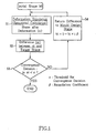
- FIG. 1 is a flowchart of the metal mold design method according to a specific embodiment of this invention.
- This invention is a metal mold design method comprising a first step (S1) of simulating the deformation that will occur in the initial shape of a molding (that is, its shape immediately prior to taking out from the metal mold) after it has been taken out from the metal mold; a second step (S2) of calculating the difference between the deformed shape obtained by this first step and a target molding shape; a third step (S3) of comparing this difference with a threshold; and a fourth step (S4) wherein, if this difference exceeds the threshold, a change is calculated in the initial shape on the basis of this difference.
- FIG. 5 is a block diagram of a metal mold design apparatus according to an embodiment of this invention.
- This invention is a metal mold design apparatus comprising keyboard 6 as means for inputting the initial shape of the metal mold (b0) in the form of three-dimensional information; deformation simulation arithmetic unit 1 as the first means which calculates a simulation of the deformation that will occur after a molding equal in shape to this initial shape has been taken out from the metal mold; difference arithmetic unit 2 as the second means which calculates the difference between the calculation result for the simulated deformation and a target molding shape; difference decision unit 3 as the third means which compares this difference with a threshold; initial shape change unit 4 as the fourth means which, if this difference exceeds the threshold, applies a change to part of the initial shape on the basis of this difference; and arithmetic controller 5 as means for causing deformation simulation arithmetic unit 1, difference arithmetic unit 2, difference decision unit 3 and initial shape change unit 4 to operate repeatedly until the aforesaid difference becomes less than the threshold.
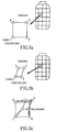
- FIG. 2 depicts a finite element model of a bottle
- FIG. 3 serves to explain the finite element method.
- a container i.e. a shape
- the finite element method is employed in similar manner to obtain the deformation of all the elements of the model shown in FIG. 2, whereby the deformed state of the entire container is found.
- the final design shape is determined by repeatedly performing the deformation simulation while little by little changing the design shape prior to deformation in such manner that the shape after deformation approaches the target molding shape.
- a first embodiment of this invention will be explained with reference to the bottle depicted in FIG. 2 as an example. If the taking out temperature is low, i.e. if there is very little deformation (and deformation is linear), then the metal mold shape that will give the target molding shape when the shrink deformation of the plastic that has been taken out from the metal mold is completed, can be obtained by multiplying the target molding shape by the reciprocal of the deformation ratio. However, this technique cannot be applied if the taking out temperature is high, i.e. if thermal shrink is large and nonlinear.
- the inventors therefore repeatedly simulated the thermal deformation that occurs in the initial shape of a molding (this shape being determined by the design shape of the metal mold), and caused any difference between this simulation result and the target molding shape to be reflected in the metal mold design shape, and repeated this process until there was a convergence to the target molding shape. They also took the nonlinearity of the deformation into consideration, and in order to stabilize the convergence, introduced a retardation coefficient for adjusting the difference that is reflected in the metal mold design shape. For this technique to work effectively, the amount of deformation and the deformed state calculated by the FEM-based deformation simulation have to be in fairly close agreement with the actual state of affairs.
- the physical property parameters were adjusted so that the simulation results matched the measured displacements, these adjustments being based on the shape before and after a measurable deformation.
- Physical property parameters include the coefficient of linear expansion, Young's modulus, Poisson's ratio, thermal conductivity, specific heat, density, and so forth. Simulation results after parameter adjustment are given in Table 1. deformation (mm) difference (measured-FEM) [difference ⁇ 100]/measured (%) measured FEM waist width -1.925 -1.886 -0.039 -2.068 waist depth 2.225 2.350 -0.125 -5.618 height of base indentation -4.780 -4.753 -0.027 -0.565
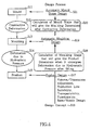
- FIG. 4 is a flowchart of a metal mold design method according to this second embodiment.
- metal mold design also takes into account the deformation due to hydrostatic pressure resulting from the molded bottle having been filled with a liquid as its contents.
- the plastic is took out from the metal mold (S11) and undergoes thermal shrink type deformation (S12), whereby a molding is obtained (S13).
- S14 thermal shrink type deformation
- S15 hydrostatic pressure
- this process is taken into consideration as well.
- product design (S17) is carried out on the basis of a design concept (S16), and the molding is automatically designed (S19) by calculating the molding shape that will give the product dimensions when it undergoes deformation due to hydrostatic pressure after being filled with the contents (S 18).
- the metal mold shape is also automatically designed (S21) by calculating the metal mold shape that will give the molding dimensions after shrink deformation (S20).
- this second embodiment has, in addition to the steps of the first embodiment, a step wherein the shape of the empty molding is compared with the shape of the molding after it has been filled with its contents, i.e. compared with the product shape, and any difference is reflected in the design shape of the metal mold.
- This procedure is similar to the first embodiment and is performed in accordance with the flowchart shown in FIG. 1. Parameters like those in the first embodiment are adjusted so that the simulation agrees with the measured displacements.
- FIG. 5 is a block diagram of a metal mold design apparatus according to this third embodiment.
- the metal mold design method disclosed in the first or second embodiment of this invention is performed by means of the metal mold design apparatus disclosed in this third embodiment.
- the initial shape of the metal mold (b0) is input in the form of three-dimensional information by means of keyboard 6.
- Deformation simulation arithmetic unit 1 calculates a simulation of the deformation that will occur after a molding equal in shape to this initial shape has been taken out from the metal mold.
- Difference arithmetic unit 2 calculates the difference between the calculated deformation and the target molding shape.
- Difference decision unit 3 compares this difference with a threshold.
- initial shape change unit 4 applies a change to the initial shape on the basis of the difference.
- Arithmetic controller 5 causes deformation simulation arithmetic unit 1, difference arithmetic unit 2, difference decision unit 3 and initial shape change unit 4 to operate repeatedly until the aforesaid difference becomes less than the threshold.
- deformation simulation arithmetic unit 1 calculates a simulation of the deformation that will occur after a molding equal in shape to the initial shape has been taken out from the metal mold, and also calculates a simulation of the subsequent deformation that occurs due to hydrostatic pressure arising when the molding has been filled with its contents.
- the metal mold was opened at a temperature of about 120°C and the cooling time was 5 seconds.
- the metal mold was opened at a temperature of about 50°C and the cooling time was a dozen or so seconds. It will therefore be seen that production per unit time was improved by a factor of at least two.
- a label is solvent bonded to a portion of the surface of a molding, the label being of a different material from the main material of which the molding surface is formed; and the first step depicted in FIG. 1 (S1) comprises simulating deformation after adding parameters relating to the material of this label, said parameters including at least its thermal conductivity and coefficient of linear expansion.
- FIG. 6 shows an in-mold labelled bottle. The FEM-based deformation simulation described previously is applied to the bottle shown in FIG. 6.
- the apparatus for performing the metal mold design method according to this fourth embodiment of the invention has the same constitution as the apparatus shown in FIG. 5, except that deformation simulation arithmetic unit 1 differs from its equivalent in the first, second and third embodiments in that it simulates deformation after adding parameters relating to the material of the label, said parameters including at least thermal conductivity and coefficient of linear expansion.
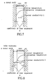
- FIG. 7 shows the resin structure and parameters of a container to which an in-mold label is not being applied.
- FIG. 8 shows the resin structure and parameters of the portion of an in-mold labelled container to which the in-mold label is being applied.
- the deformation by thermal shrink of an in-mold labelled container can then be simulated using the physical properties of the resins derived in this way.
- the physical properties of both the resin used for the bottle (HDPE) and the resin used for the label (PP) can be derived from the physical properties, obtained in this way, of the resin of the unlabelled container and the resin of the in-mold labelled container, by way of subtractive considerations.
- the thermal conductivity and coefficient of linear expansion of both the bottle resin (HDPE) and the label resin (PP) obtained in this fourth embodiment are shown in Table 2.
- the deformation by thermal shrink of a container is simulated using the physical properties of the resins derived in this way.
- FIG. 9 which compares simulated deformation by thermal shrink and actual measurements of moldings, the distance from the base of the bottle (i.e. height) is plotted along the horizontal axis, and the distance from the center of the base of the bottle is plotted along the vertical axis.
- Table 3 the errors between measured values and simulated deformation can be made extremely small.
- the width and depth given in Table 3 are the width and depth at the part of the bottle corresponding to a height of 100 mm. height of base indentation width depth measured 182.67 94.44 52.94 simulation 183.08 95.12 52.61 difference -0.41 -0.68 0.33
- a metal mold is designed by simulating the deformation due to thermal shrink of an in-mold labelled container.
- deformation of the initial design shape of a metal mold (b0) due to thermal shrink is simulated, and any difference between this simulation result and the target molding shape is reflected in the metal mold design shape, and this process is repeated until there is a convergence to the target molding shape.
- the nonlinearity of the deformation is taken into consideration, and in order to stabilize the convergence, a retardation coefficient is introduced for adjusting the difference that is reflected in the metal mold design shape.
- the amount of deformation and the deformed state calculated by the FEM-based deformation simulation have to be in fairly close agreement with the actual state of affairs.
- the physical property parameters are adjusted so that the simulation results match the measured displacements, these adjustments being based on the shape before and after a measurable deformation.
- Physical property parameters include the coefficient of linear expansion, Young's modulus, Poisson's ratio, thermal conductivity, specific heat, density, and so forth. Deformation simulation results after parameter adjustment are given in Table 1.
- a metal mold can be designed taking into account the deformation due to hydrostatic pressure resulting from the molded bottle being filled with a liquid as its contents, and this can be applied also to an in-mold labelled bottle according to the fourth embodiment of this invention.
- the metal mold was opened at a temperature of about 120 °C and the cooling time was 5 seconds.
- the metal mold was opened at a temperature of about 50°C and the cooling time was a dozen or so seconds. It will therefore be seen that production per unit time was improved by a factor of at least two.
Landscapes
- Engineering & Computer Science (AREA)
- Manufacturing & Machinery (AREA)
- Mechanical Engineering (AREA)
- Moulds For Moulding Plastics Or The Like (AREA)
- Blow-Moulding Or Thermoforming Of Plastics Or The Like (AREA)
- Knitting Machines (AREA)
- Transplanting Machines (AREA)
- Floor Finish (AREA)
- Containers Having Bodies Formed In One Piece (AREA)
Description
| deformation (mm) | difference (measured-FEM) | [difference ×100]/measured (%) | ||
| measured | FEM | |||
| waist width | -1.925 | -1.886 | -0.039 | -2.068 |
| waist depth | 2.225 | 2.350 | -0.125 | -5.618 |
| height of base indentation | -4.780 | -4.753 | -0.027 | -0.565 |
| Unit | HDPE | PP | |
| thermal conductivity | cal/mm s °C | 1.0E-4 | 1.0E-5 |
| thermal conductance (air) | cal/mm s2 °C | 4.78E-6 | - |
| thermal conductance (mold) | cal/mm s2 °C | 6.21E-5 | 1.00E-5 |
| specific heat | cal/kg °C | 550. | 460. |
| density | kg/mm3 | 955E-6 | .900E-6 |
| thermal transmission efficiency | E-7 m2/s | 1.90 | 2.42E-1 |
| coefficient of linear expansion (height) | /°C | 1.52E-4 | 2.00E-5 |
| coefficient of linear expansion (around) | /°C | 3.20E-4 | 2.00E-5 |
| Young's modulus | Kg f/mm2 | 3.0 | 1.0 |
| Poison ratio | - | 0.4 | 0.4 |
| height of base indentation | width | depth | |
| measured | 182.67 | 94.44 | 52.94 |
| simulation | 183.08 | 95.12 | 52.61 |
| difference | -0.41 | -0.68 | 0.33 |
| dimension (mm) | difference (test piece -design value) | [difference × 100]/design value (%) | |||
| design value | test piece | ||||
| maximum height | 74.2 | 73.71 | -0.49 | -0.66 | |
| maximum thickness | 38.7 | 39.01 | 0.31 | 0.80 | |
| shoulder width | 72.0 | 71.17 | -0.83 | -1.15 | |
| shoulder thickness | 37.4 | 37.48 | 0.08 | 0.21 | |
| waist width | 59.1 | 58.56 | -0.54 | -0.91 | |
| waist thickness | 29.6 | 29.90 | 0.30 | 1.01 | |
| overall height | 216.5 | 217.07 | 0.57 | 0.26 | |
| nozzle height | 17.5 | 17.79 | 0.29 | 1.66 | |
| inner diameter of mouth | width | 18.3 | 18.67 | 0.37 | 2.02 |
| thickness | ^ | 18.04 | -0.26 | -1.42 | |
| peak-to-peak thread diameter | width | 25.2 | 24.88 | -0.32 | -1.27 |
| thickness | ^ | 24.92 | -0.28 | -1.11 |
Claims (9)
- A method for designing a metal mold for a blow molding process, comprising a first step of simulating, using a finite element method, the deformation that will occur in the initial shape of a blow molded molding (its shape immediately prior to take out from the metal mold) after it has been taken out from the metal mold at a temperature such that it will deform in a non-linear manner, wherein the finite element method comprises applying an adjustment of coefficient of thermal expansion, Young's modulus, Poisson's ratio, thermal conductivity, specific heat and density of the molding material; a second step of calculating the difference between the deformed shape obtained by this first step and a target molding shape; a third step of comparing this difference with a threshold; and a fourth step wherein, if this difference exceeds said threshold, a change is calculated in the aforesaid initial shape on the basis of this difference.
- A method for designing a metal mold according to claim 1, wherein a label is solvent bonded to a portion of the surface of the aforesaid molding, this label being of a different material from the main material of which the molding surface is formed; and the aforesaid first step comprises simulating deformation after adding parameters relating to the material of this label, said parameters including at least its thermal conductivity and coefficient of linear expansion.
- A method for designing a metal mold according to claim 1 or 2, wherein the aforesaid target molding shape does not include the deformation due to the internal pressure produced when the molding is filled with contents.
- A method for designing a metal mold according to Claim 1 or 2, wherein the aforesaid target molding shape includes the deformation due to the internal pressure produced when the molding is filled with contents.
- An apparatus for designing a metal mold for a blow molding process, the apparatus comprising means for inputting the initial shape of the metal mold (b0) in the form of three-dimensional information; and the following four means: a first means for calculating a simulation, using a finite element method, of the deformation that will occur after a blow molded molding equal in shape to this initial shape has been taken out from the metal mold at a temperature such that it will deform in a non-linear manner, the first means comprising means for applying an adjustment of coefficient of thermal expansion. Young's modulus, Poisson's ratio, thermal conductivity, specific heat and density of the molding material; a second means for calculating the difference (xi) between the calculation result for the simulated deformation (ci) and a target molding shape; a third means for comparing this difference with a threshold; and a fourth means which, if this difference exceeds the threshold (t), applies a change to the aforesaid initial shape on the basis of this difference; and means for causing the aforesaid first to fourth means to operate repeatedly until the aforesaid difference becomes less than the threshold.
- An apparatus for designing a metal mold according to claim 5, wherein a label is solvent bonded to a portion of the surface of the aforesaid molding, this label being of a different material from the main material of which the molding surface is formed; and the aforesaid first means simulates deformation after adding parameters relating to the material of this label, said parameters including at least its thermal conductivity and coefficient of linear expansion.
- An apparatus for designing a metal mold according to claim 5 or claim 6, wherein the aforesaid target molding shape does not include the deformation due to the internal pressure produced when the molding is filled with contents.
- An apparatus for designing a metal mold according to claim 5 or claim 6, wherein the aforesaid target molding shape includes the deformation due to the internal pressure . produced when the molding is filled with contents.
- A machine readable recording medium on which is recorded a program for causing each means recited in any of claims 5 to 8 to operate.
Applications Claiming Priority (7)
| Application Number | Priority Date | Filing Date | Title |
|---|---|---|---|
| JP8089690A JP2955509B2 (en) | 1996-04-11 | 1996-04-11 | Mold design method and apparatus |
| JP89690/96 | 1996-04-11 | ||
| JP8969096 | 1996-04-11 | ||
| JP570897 | 1997-01-16 | ||
| JP5708/97 | 1997-01-16 | ||
| JP9005708A JP2957503B2 (en) | 1997-01-16 | 1997-01-16 | Mold design method |
| PCT/JP1997/001229 WO1997037823A1 (en) | 1996-04-11 | 1997-04-10 | Mold designing method and apparatus |
Publications (3)
| Publication Number | Publication Date |
|---|---|
| EP0844057A1 EP0844057A1 (en) | 1998-05-27 |
| EP0844057A4 EP0844057A4 (en) | 2000-01-12 |
| EP0844057B1 true EP0844057B1 (en) | 2004-06-16 |
Family
ID=26339696
Family Applications (1)
| Application Number | Title | Priority Date | Filing Date |
|---|---|---|---|
| EP97915694A Expired - Lifetime EP0844057B1 (en) | 1996-04-11 | 1997-04-10 | Mold designing method and apparatus |
Country Status (6)
| Country | Link |
|---|---|
| US (1) | US6304794B1 (en) |
| EP (1) | EP0844057B1 (en) |
| CN (1) | CN1084661C (en) |
| DE (1) | DE69729533T2 (en) |
| TW (1) | TW333478B (en) |
| WO (1) | WO1997037823A1 (en) |
Families Citing this family (26)
| Publication number | Priority date | Publication date | Assignee | Title |
|---|---|---|---|---|
| DE19841389A1 (en) * | 1998-09-10 | 2000-03-16 | Abb Research Ltd | Process for generating a molded shell for a casting |
| FR2804286B1 (en) | 2000-01-28 | 2002-09-06 | Oreal | USE OF POLYAMINOACID DERIVATIVES AS PRESERVATIVES, COMPOSITIONS COMPRISING THE SAME AND STORAGE METHOD USING THE SAME |
| TWI224546B (en) * | 2000-03-07 | 2004-12-01 | Kao Corp | Method and apparatus for designing molds, extruder dies and cores |
| US7024342B1 (en) * | 2000-07-01 | 2006-04-04 | Mercury Marine | Thermal flow simulation for casting/molding processes |
| US6766207B2 (en) * | 2000-08-25 | 2004-07-20 | Fujitsu Limited | Designing method, CAD apparatus and storage medium |
| US20020120356A1 (en) * | 2001-02-26 | 2002-08-29 | Keiichi Takahashi | Container designing system, container designing method, container designing program and recording medium for recording container designing program |
| TWI338262B (en) * | 2003-07-25 | 2011-03-01 | Hon Hai Prec Ind Co Ltd | A system and method for managing module development |
| DE10342147B4 (en) * | 2003-09-12 | 2007-05-10 | Daimlerchrysler Ag | Method of calculating the cavity geometry of a master tool |
| JP2007213269A (en) * | 2006-02-08 | 2007-08-23 | Toshiba Corp | Stress analysis method, wiring structure design method, program, and semiconductor device manufacturing method |
| JP4271246B2 (en) * | 2007-04-09 | 2009-06-03 | 株式会社デンソー | Method and apparatus for predicting deformation due to shrinkage of molded product |
| JP2009037162A (en) * | 2007-08-03 | 2009-02-19 | Panasonic Corp | Cylindrical molded products, lens barrels, cameras and injection molds |
| JP4749393B2 (en) * | 2007-08-03 | 2011-08-17 | パナソニック株式会社 | Cylindrical molded product, injection mold and cylindrical molded product manufacturing method |
| DE102009040803A1 (en) | 2009-08-25 | 2011-04-14 | Khs Corpoplast Gmbh & Co. Kg | Method and apparatus for blow molding containers |
| CN102682171B (en) * | 2012-05-15 | 2014-12-31 | 中国电子科技集团公司第五十四研究所 | Method for compensating thermal deformation of mold for high-precision composite material antenna reflector unit |
| KR101325834B1 (en) * | 2013-05-07 | 2013-11-05 | 윤남운 | Mobile phone protection case with trnsparent part and its making method |
| US9573306B2 (en) * | 2014-01-10 | 2017-02-21 | Western Digital Technologies, Inc. | Injection molding part with “zero draft” design and manufacturing methodologies |
| CN104441488A (en) * | 2014-12-23 | 2015-03-25 | 广州科技职业技术学院 | Predeformation method and system of unequal-wall-thickness plastic part mold parting surface |
| CN105983608B (en) * | 2015-02-02 | 2018-04-17 | 上海赛科利汽车模具技术应用有限公司 | The control method of the plate influx of auto sound doubling plate drawing die |
| US10315340B2 (en) * | 2015-05-08 | 2019-06-11 | GM Global Technology Operations LLC | Methods and systems for modeling of distortion in molded composites |
| EP3362247B1 (en) * | 2015-10-12 | 2020-03-11 | PPG Industries Ohio, Inc. | Mold for making a polymeric aircraft window panel |
| CN106626449B (en) * | 2015-11-24 | 2018-11-27 | 北京航空航天大学 | Consider the design method in the composite material V-type component autoclave molding tooling type face of curing deformation |
| CN105599177A (en) * | 2015-12-30 | 2016-05-25 | 苏州乔布注塑工业有限公司 | Manufacturing method of temperature control injection mold |
| CN105599185B (en) * | 2016-03-11 | 2018-06-29 | 武汉华星光电技术有限公司 | A kind of manufacturing method of light-conducting board mold |
| CN111278562A (en) * | 2017-08-28 | 2020-06-12 | 普梭梅根公司 | Device for protecting and sealing the opening of a container |
| CN111497163B (en) * | 2018-12-28 | 2023-06-20 | 株式会社捷太格特 | Quality prediction system and molding machine |
| CN112406129B (en) * | 2020-10-29 | 2021-11-30 | 清华大学 | Production method and production system of rubber part |
Family Cites Families (14)
| Publication number | Priority date | Publication date | Assignee | Title |
|---|---|---|---|---|
| KR920004583B1 (en) * | 1988-10-31 | 1992-06-11 | 가부시끼가이샤 히다찌세이사꾸쇼 | Method and apparatus for measuring flow and curing characteristices of resin |
| US5435818A (en) * | 1992-06-02 | 1995-07-25 | Canon Kabushiki Kaisha | Mold for optical element and a method of molding optical element |
| JP2698520B2 (en) * | 1992-08-31 | 1998-01-19 | 日立金属株式会社 | How to make a casting plan for a breathable mold |
| JP2898197B2 (en) * | 1993-06-18 | 1999-05-31 | キヤノン株式会社 | Optical element, molding method thereof, and laser scanning optical system |
| JPH079522A (en) * | 1993-06-23 | 1995-01-13 | Sekisui Chem Co Ltd | Mold design method |
| JPH079523A (en) * | 1993-06-25 | 1995-01-13 | Sekisui Chem Co Ltd | Injection molding method and injection molding die design method |
| JPH07112481A (en) * | 1993-10-19 | 1995-05-02 | Denki Kagaku Kogyo Kk | Blow Molding Bottle Shape Design Method by Blow Molding Analysis |
| JPH07117113A (en) * | 1993-10-21 | 1995-05-09 | Denki Kagaku Kogyo Kk | Design method for optimum blow molding temperature by blow molding analysis |
| JP3501486B2 (en) * | 1993-12-27 | 2004-03-02 | キヤノン株式会社 | Method and apparatus for estimating deformation of injection-molded article |
| JPH0812481A (en) * | 1994-06-29 | 1996-01-16 | Otsuka Chem Co Ltd | Gas-generating agent for air bag |
| JPH0817113A (en) * | 1994-06-29 | 1996-01-19 | Sony Corp | Tape player device |
| JPH08257741A (en) * | 1995-03-24 | 1996-10-08 | Hitachi Metals Ltd | Method for predicting casting defect utilizing numerical analysis |
| US5908128A (en) * | 1995-07-17 | 1999-06-01 | Continental Pet Technologies, Inc. | Pasteurizable plastic container |
| US5925208A (en) * | 1995-09-13 | 1999-07-20 | Northstar Print Group | Process for the production of printed in-mold labeled molded containers |
-
1997
- 1997-04-10 DE DE69729533T patent/DE69729533T2/en not_active Expired - Lifetime
- 1997-04-10 CN CN97190340A patent/CN1084661C/en not_active Expired - Fee Related
- 1997-04-10 EP EP97915694A patent/EP0844057B1/en not_active Expired - Lifetime
- 1997-04-10 WO PCT/JP1997/001229 patent/WO1997037823A1/en not_active Ceased
- 1997-04-11 TW TW086104673A patent/TW333478B/en not_active IP Right Cessation
- 1997-12-10 US US08/988,240 patent/US6304794B1/en not_active Expired - Fee Related
Also Published As
| Publication number | Publication date |
|---|---|
| CN1188441A (en) | 1998-07-22 |
| WO1997037823A1 (en) | 1997-10-16 |
| CN1084661C (en) | 2002-05-15 |
| DE69729533T2 (en) | 2004-11-11 |
| US6304794B1 (en) | 2001-10-16 |
| DE69729533D1 (en) | 2004-07-22 |
| EP0844057A1 (en) | 1998-05-27 |
| EP0844057A4 (en) | 2000-01-12 |
| TW333478B (en) | 1998-06-11 |
Similar Documents
| Publication | Publication Date | Title |
|---|---|---|
| US6304794B1 (en) | Method for designing a metal mold | |
| JP3226447B2 (en) | Simulation method of press molding or injection press molding | |
| CN109822849B (en) | Molding system and setting method thereof | |
| JP4378011B2 (en) | Mold design equipment and mold shape design method | |
| JPH0622840B2 (en) | Molding process simulation system | |
| KR20010088405A (en) | Method and apparatus for designing molds, extruder dies and cores | |
| Kim et al. | Birefringence in injection‐compression molding of amorphous polymers: Simulation and experiment | |
| JP2955509B2 (en) | Mold design method and apparatus | |
| Yang et al. | Numerical prediction of phase‐change heat conduction of injection‐molded high density polyethylene thick‐walled parts via the enthalpy transforming model with mushy zone | |
| Bhagavatula et al. | Modelling and verification of ejection forces in thermoplastic injection moulding | |
| JP2998596B2 (en) | Fluid flow process analysis device, analysis method, injection molding process analysis device, analysis method, injection molded product, and method for manufacturing injection molded product | |
| Guo et al. | Warpage of injection-molded thermoplastics parts: Numerical simulation and experimental validation | |
| JP2957503B2 (en) | Mold design method | |
| JP2000313035A (en) | Injection molding process simulation method and apparatus, and method for manufacturing resin molded product using the result | |
| Suvanjumrat et al. | [RETRACTED ARTICLE] Blow Molding Simulation using Cross-Section Technique for Complex Shape Bottles | |
| Zhou et al. | Integrated simulation of the injection molding process with stereolithography molds | |
| US10864667B2 (en) | Molding system for preparing an in-mold decorated article | |
| Liu et al. | Numerical simulations of residual stresses and warpage in injection molding | |
| Hioe et al. | A simplified approach to predict part temperature and minimum “safe” cycle time | |
| JP3650338B2 (en) | Mold design method and apparatus, and extrusion die and core design method and apparatus | |
| Koziey et al. | Computer simulation of thermoforming | |
| JPH02258229A (en) | Method and apparatus for simulating molding process | |
| JPH07108595A (en) | Design method of preform or parison shape by blow molding analysis | |
| BARON et al. | COMPARISON OF SELECTED MATERIALS INTENDED FOR THE MANUFACTURE OF PLASTIC HOLDER FOR REVERSE PARKING SENSOR WITH THE USE OF COMPUTER SIMULATION TOOLS. | |
| JPH07112481A (en) | Blow Molding Bottle Shape Design Method by Blow Molding Analysis |
Legal Events
| Date | Code | Title | Description |
|---|---|---|---|
| PUAI | Public reference made under article 153(3) epc to a published international application that has entered the european phase |
Free format text: ORIGINAL CODE: 0009012 |
|
| 17P | Request for examination filed |
Effective date: 19971230 |
|
| AK | Designated contracting states |
Kind code of ref document: A1 Designated state(s): DE FR GB IT |
|
| RIC1 | Information provided on ipc code assigned before grant |
Free format text: 6B 29C 33/38 A, 6B 29C 49/48 B, 6B 29C 37/00 B |
|
| A4 | Supplementary search report drawn up and despatched |
Effective date: 19991125 |
|
| AK | Designated contracting states |
Kind code of ref document: A4 Designated state(s): DE FR GB IT |
|
| 17Q | First examination report despatched |
Effective date: 20000519 |
|
| GRAP | Despatch of communication of intention to grant a patent |
Free format text: ORIGINAL CODE: EPIDOSNIGR1 |
|
| GRAS | Grant fee paid |
Free format text: ORIGINAL CODE: EPIDOSNIGR3 |
|
| GRAA | (expected) grant |
Free format text: ORIGINAL CODE: 0009210 |
|
| AK | Designated contracting states |
Kind code of ref document: B1 Designated state(s): DE FR GB IT |
|
| REG | Reference to a national code |
Ref country code: GB Ref legal event code: FG4D |
|
| REF | Corresponds to: |
Ref document number: 69729533 Country of ref document: DE Date of ref document: 20040722 Kind code of ref document: P |
|
| ET | Fr: translation filed | ||
| PLBE | No opposition filed within time limit |
Free format text: ORIGINAL CODE: 0009261 |
|
| STAA | Information on the status of an ep patent application or granted ep patent |
Free format text: STATUS: NO OPPOSITION FILED WITHIN TIME LIMIT |
|
| 26N | No opposition filed |
Effective date: 20050317 |
|
| PGFP | Annual fee paid to national office [announced via postgrant information from national office to epo] |
Ref country code: GB Payment date: 20100325 Year of fee payment: 14 |
|
| PGFP | Annual fee paid to national office [announced via postgrant information from national office to epo] |
Ref country code: FR Payment date: 20100521 Year of fee payment: 14 |
|
| PGFP | Annual fee paid to national office [announced via postgrant information from national office to epo] |
Ref country code: IT Payment date: 20100420 Year of fee payment: 14 Ref country code: DE Payment date: 20100430 Year of fee payment: 14 |
|
| REG | Reference to a national code |
Ref country code: DE Ref legal event code: R119 Ref document number: 69729533 Country of ref document: DE |
|
| REG | Reference to a national code |
Ref country code: DE Ref legal event code: R119 Ref document number: 69729533 Country of ref document: DE |
|
| GBPC | Gb: european patent ceased through non-payment of renewal fee |
Effective date: 20110410 |
|
| REG | Reference to a national code |
Ref country code: FR Ref legal event code: ST Effective date: 20111230 |
|
| PG25 | Lapsed in a contracting state [announced via postgrant information from national office to epo] |
Ref country code: FR Free format text: LAPSE BECAUSE OF NON-PAYMENT OF DUE FEES Effective date: 20110502 |
|
| PG25 | Lapsed in a contracting state [announced via postgrant information from national office to epo] |
Ref country code: GB Free format text: LAPSE BECAUSE OF NON-PAYMENT OF DUE FEES Effective date: 20110410 Ref country code: IT Free format text: LAPSE BECAUSE OF NON-PAYMENT OF DUE FEES Effective date: 20110410 |
|
| PG25 | Lapsed in a contracting state [announced via postgrant information from national office to epo] |
Ref country code: DE Free format text: LAPSE BECAUSE OF NON-PAYMENT OF DUE FEES Effective date: 20111031 |