EP0844039B1 - Procede de soudage horizontal et appareillage de soudage - Google Patents
Procede de soudage horizontal et appareillage de soudage Download PDFInfo
- Publication number
- EP0844039B1 EP0844039B1 EP97920937A EP97920937A EP0844039B1 EP 0844039 B1 EP0844039 B1 EP 0844039B1 EP 97920937 A EP97920937 A EP 97920937A EP 97920937 A EP97920937 A EP 97920937A EP 0844039 B1 EP0844039 B1 EP 0844039B1
- Authority
- EP
- European Patent Office
- Prior art keywords
- welding
- molten pool
- current
- heat source
- wires
- Prior art date
- Legal status (The legal status is an assumption and is not a legal conclusion. Google has not performed a legal analysis and makes no representation as to the accuracy of the status listed.)
- Expired - Lifetime
Links
Images


Classifications
-
- B—PERFORMING OPERATIONS; TRANSPORTING
- B23—MACHINE TOOLS; METAL-WORKING NOT OTHERWISE PROVIDED FOR
- B23K—SOLDERING OR UNSOLDERING; WELDING; CLADDING OR PLATING BY SOLDERING OR WELDING; CUTTING BY APPLYING HEAT LOCALLY, e.g. FLAME CUTTING; WORKING BY LASER BEAM
- B23K15/00—Electron-beam welding or cutting
- B23K15/0046—Welding
-
- B—PERFORMING OPERATIONS; TRANSPORTING
- B23—MACHINE TOOLS; METAL-WORKING NOT OTHERWISE PROVIDED FOR
- B23K—SOLDERING OR UNSOLDERING; WELDING; CLADDING OR PLATING BY SOLDERING OR WELDING; CUTTING BY APPLYING HEAT LOCALLY, e.g. FLAME CUTTING; WORKING BY LASER BEAM
- B23K26/00—Working by laser beam, e.g. welding, cutting or boring
- B23K26/14—Working by laser beam, e.g. welding, cutting or boring using a fluid stream, e.g. a jet of gas, in conjunction with the laser beam; Nozzles therefor
- B23K26/1423—Working by laser beam, e.g. welding, cutting or boring using a fluid stream, e.g. a jet of gas, in conjunction with the laser beam; Nozzles therefor the flow carrying an electric current
-
- B—PERFORMING OPERATIONS; TRANSPORTING
- B23—MACHINE TOOLS; METAL-WORKING NOT OTHERWISE PROVIDED FOR
- B23K—SOLDERING OR UNSOLDERING; WELDING; CLADDING OR PLATING BY SOLDERING OR WELDING; CUTTING BY APPLYING HEAT LOCALLY, e.g. FLAME CUTTING; WORKING BY LASER BEAM
- B23K26/00—Working by laser beam, e.g. welding, cutting or boring
- B23K26/20—Bonding
- B23K26/21—Bonding by welding
- B23K26/24—Seam welding
-
- B—PERFORMING OPERATIONS; TRANSPORTING
- B23—MACHINE TOOLS; METAL-WORKING NOT OTHERWISE PROVIDED FOR
- B23K—SOLDERING OR UNSOLDERING; WELDING; CLADDING OR PLATING BY SOLDERING OR WELDING; CUTTING BY APPLYING HEAT LOCALLY, e.g. FLAME CUTTING; WORKING BY LASER BEAM
- B23K26/00—Working by laser beam, e.g. welding, cutting or boring
- B23K26/346—Working by laser beam, e.g. welding, cutting or boring in combination with welding or cutting covered by groups B23K5/00 - B23K25/00, e.g. in combination with resistance welding
- B23K26/348—Working by laser beam, e.g. welding, cutting or boring in combination with welding or cutting covered by groups B23K5/00 - B23K25/00, e.g. in combination with resistance welding in combination with arc heating, e.g. TIG [tungsten inert gas], MIG [metal inert gas] or plasma welding
-
- B—PERFORMING OPERATIONS; TRANSPORTING
- B23—MACHINE TOOLS; METAL-WORKING NOT OTHERWISE PROVIDED FOR
- B23K—SOLDERING OR UNSOLDERING; WELDING; CLADDING OR PLATING BY SOLDERING OR WELDING; CUTTING BY APPLYING HEAT LOCALLY, e.g. FLAME CUTTING; WORKING BY LASER BEAM
- B23K37/00—Auxiliary devices or processes, not specially adapted to a procedure covered by only one of the preceding main groups
- B23K37/06—Auxiliary devices or processes, not specially adapted to a procedure covered by only one of the preceding main groups for positioning the molten material, e.g. confining it to a desired area
-
- B—PERFORMING OPERATIONS; TRANSPORTING
- B23—MACHINE TOOLS; METAL-WORKING NOT OTHERWISE PROVIDED FOR
- B23K—SOLDERING OR UNSOLDERING; WELDING; CLADDING OR PLATING BY SOLDERING OR WELDING; CUTTING BY APPLYING HEAT LOCALLY, e.g. FLAME CUTTING; WORKING BY LASER BEAM
- B23K9/00—Arc welding or cutting
- B23K9/08—Arrangements or circuits for magnetic control of the arc
-
- B—PERFORMING OPERATIONS; TRANSPORTING
- B23—MACHINE TOOLS; METAL-WORKING NOT OTHERWISE PROVIDED FOR
- B23K—SOLDERING OR UNSOLDERING; WELDING; CLADDING OR PLATING BY SOLDERING OR WELDING; CUTTING BY APPLYING HEAT LOCALLY, e.g. FLAME CUTTING; WORKING BY LASER BEAM
- B23K9/00—Arc welding or cutting
- B23K9/16—Arc welding or cutting making use of shielding gas
- B23K9/167—Arc welding or cutting making use of shielding gas and of a non-consumable electrode
- B23K9/1675—Arc welding or cutting making use of shielding gas and of a non-consumable electrode making use of several electrodes
-
- B—PERFORMING OPERATIONS; TRANSPORTING
- B23—MACHINE TOOLS; METAL-WORKING NOT OTHERWISE PROVIDED FOR
- B23K—SOLDERING OR UNSOLDERING; WELDING; CLADDING OR PLATING BY SOLDERING OR WELDING; CUTTING BY APPLYING HEAT LOCALLY, e.g. FLAME CUTTING; WORKING BY LASER BEAM
- B23K9/00—Arc welding or cutting
- B23K9/16—Arc welding or cutting making use of shielding gas
- B23K9/173—Arc welding or cutting making use of shielding gas and of a consumable electrode
- B23K9/1735—Arc welding or cutting making use of shielding gas and of a consumable electrode making use of several electrodes
Definitions
- This invention concerns a method of welding in the horizontal position, in which the molten pool is liable to experience deformation under the influence of gravity, and a welding apparatus for that purpose. More specifically, it concerns a welding method in the horizontal position to be used in the production of large structures such as smokestacks, bridges, pressure vessels and the like, and a welding apparatus for that purpose. It also concerns an apparatus for performing the method.
- Welding has been an indispensable process in the manufacture of large steel structures such as smokestacks, bridges and pressure vessels. Because such large structures cannot easily be inverted during production, some portions must be welded in the horizontal position.
- welding in the overhead position refers to welding a joint from below with the axis of the weld approximately horizontal.
- Welding in the flat position refers to welding a joint from above with the axis of the weld approximately horizontal.
- Welding in the horizontal position refers to welding a joint from the side with the axis of the weld approximately horizontal.
- Welding in the vertical position refers to welding a joint with a vertical axis of the weld lengthwise along the vertical.
- welding in the horizontal position will refer to welds such that the angle of the parent material with respect to a horizontal surface is either approximately vertical or within the range of 45° to 90°; and the weld line is either approximately horizontal or its angle with respect to a horizontal surface is within the range of 0° to 45°.
- the present invention is also applicable in a range of welding positions which might be called intermediate between the common overhead, flat and horizontal positions.
- horizontal position in the wider meaning specified above.
- JP-A-63-119980 which represents the closest prior art, discloses a welding method which uses a coil to produce a magnetic force to push the molten welding pool up against the force of gravity.
- a preferred embodiment of the present invention is designed as follows. It concerns a method of welding in the horizontal position, in which a heat source such as an arc, a laser or an electron beam is used to melt the parent material and form a molten pool. Because of the position of the weld, gravity tends to cause the bead to deform.
- a heat source such as an arc, a laser or an electron beam
- a current is made to flow in the molten pool in approximately the same direction as the weld line, and a magnetic field is induced in the molten pool orthogonal to the direction of the current.
- the joint is welded while an upward Lorentz force (opposite the direction of gravity) is generated in the molten pool.
- the means by which a current is made to flow in the direction of the weld line in the molten pool comprise a plurality of auxiliary wires. These wires are inserted into the molten pool and a current is passed through them. The current, ideally a unidirectional current, is made to flow in the molten pool in the direction of the weld line.
- a welding apparatus which is advantageous to implement the welding method comprises: a heat source for welding comprising an arc, a laser or an electron beam; a plurality of auxiliary wires placed so as to face the molten pool formed by the heat source; a power supply for generating a current to run through the wires; and a magnetic field inducing means to induce a magnetic field in the molten pool which intersects the surface of the parent material.
- an apparatus can be provided to pass a portion of the welding current into the auxiliary wires.
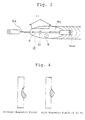
- auxiliary wires 5a and 5b are used. As is shown in Figure 1, the minus and plus sides of power supply 2 are connected to the respective wires. In addition to this, or instead of power supply 2, a portion of the welding current can be passed to auxiliary wire 5b, as shown in Figure 2.
- a current is conducted between auxiliary wires 5a and 5b, a unidirectional current A is created in molten pool 12.
- a Lorentz force 11 is activated in the direction which allows it to support the molten pool. This prevents the weld bead from sagging.
- auxiliary wires 5a and 5b When a current is conducted through auxiliary wires 5a and 5b, these wires are heated by the Joule effect, and their deposition rate is enhanced.
- the surface area of the wires which can absorb the radiant heat of the arc will be larger. Thus the melting capability of the wires will increase.
- the TIG hot-wire welding method is similar to the method according to this invention.
- heating power supply 102 which passes a current into consumable wire 101, is separate from TIG arc power supply 100.
- Current is supplied to consumable wire 101 from a point approximately 10 cm away from parent material 7, and the resistance heating heats wire 101. Since wire 101 is sent to the molten pool in a half-melted state, the deposition rate is increased by up to three times that of the usual method.
- the TIG hot-wire welding method and that according to the present embodiment have in common that they both involve supplying current to a consumable wire.
- the object of the former method is to heat the wire by resistance and send it to the molten pool in a half-melted state.
- That of the present embodiment is to pass a current through multiple melting wires in the direction of the weld line, and so induce a magnetic field in the molten pool 12 which is roughly orthogonal to the current. In this way a Lorentz force 11 will be activated in an upward direction in the molten pool 12.
- the former uses a single consumable wire
- the present embodiment uses two auxiliary wires, 5a and 5b, to pass a current in molten pool 12 in the direction of the weld line.
- Auxiliary wires 5a and 5b need not be consumable wires.
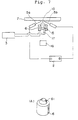
- an apparatus may be provided, as shown in Figure 7, which concentrates the heat source and applies a magnetic field.
- the present invention is particularly advantageously applied when the weld line is approximately horizontal and the surface of the parent material is approximately vertical.
- the effects of this invention are readily achieved throughout the range of horizontal position welding defined above, so long as a Lorentz force is generated in an upward direction (against the force of gravity) in the molten pool while the joint is welded.
- Figure 1 shows the circuit connections in a welding apparatus in the horizontal position which is a first preferred embodiment of this invention.
- Figure 2 shows the circuit connections in a welding apparatus in the horizontal position which is a second preferred embodiment of this invention.
- Figure 3 is a drawing to illustrate how the molten metal is supported in a method of welding in the horizontal position according to an embodiment of this invention.
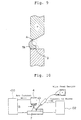
- Figure 4 shows cross sections of the bead in horizontal position welding.
- A shows the appearance of the bead without the application of a magnetic field.
- B is a cross section of a bead produced by an embodiment of this invention.
- Figure 5 shows the circuit connections in a welding apparatus in the horizontal position which is a third preferred embodiment of this invention.
- Figure 6 shows the circuit connections in a welding apparatus in the horizontal position which is a fourth preferred embodiment of this invention.
- FIG. 7 shows the circuit connections in a welding apparatus in the horizontal position which is a fifth preferred embodiment of this invention.
- (A) is an enlarged perspective drawing of the magnetic coil.
- Figure 8 shows the circuit connections in a welding apparatus in the horizontal position which is a sixth preferred embodiment of this invention.
- Figure 9 is a cross section of the welding area when the prior art welding method is used.
- Figure 10 shows an apparatus employing the TIG hot-wire welding method, a method belonging to the prior art.
- FIGs 1, 3 and 4 show a first preferred embodiment of this invention.
- This method, and the apparatus to make use of it, are used in TIG welding in the horizontal position. It employs an arc for heat source 10 and a nonconsumable electrode (a tungsten electrode) for electrode 13.
- a tungsten electrode a tungsten electrode
- 1 is the welding power supply.
- a TIG welding power supply with DC constant current characteristics is used.
- An arc (the heat source) is generated between electrode 13, which protrudes from welding torch 4, and parent material 7. The heat of the arc melts the parent material.
- auxiliary (melting) wires 5a and 5b are placed on molten pool 12 on either side of arc heat source 10.
- the wires 5a and 5b are connected, respectively, to the minus and plus sides of power supply 2. In this way a current is made to flow horizontally parallel to the weld line.
- the power supply 2 supplies a direct current and generates a constant electric field.
- a current splitting device 8 shown in Figure 2 can be used to pass a portion of the welding current to wire 5b.
- Current splitting device 8 may comprise two variable resistors so that the current supplied to auxiliary wire 5b may be varied.
- the welding torch 4 is surrounded by magnetic coil 6, which is connected to power supply 3.
- Magnetic field 9 can be induced in the direction which appears to be upward in Figure 1 (horizontally and orthogonal to the weld line).
- auxiliary wires 5a and 5b When a current is passed through auxiliary wires 5a and 5b, they are heated by the Joule effect just as in TIG hot-wire welding methods belonging to the prior art, and their deposition rate increases.
- the present invention makes use of multiple wires, 5a and 5b, so there is a greater surface area of these wires to absorb the radiant heat of arc heat source 10. As a result, the melting capacity of wires 5a and 5b is increased.
- the effect of this embodiment is verified from the shape of the bead obtained in a bead-on-plate welding test.
- the conditions of welding are a welding current of DC:500 A and a current to the wires of DC:120 A.
- the deposition rate of wires 5a and 5b is 100 g/min.
- the welding speed is 50 cm/min.
- the strength of the magnetic field 9 applied to molten pool 12 can be varied.
- the magnetic density is varied by changing the strength of the current from power supply 3 to magnetic coil 6, which is wound around TIG welding torch 4 as shown in Figure 1. Varying this current during welding will cause the magnetic flux density to vary.
- Figure 4 shows two cross sections of the welding location. In the one on the left, no magnetic field is applied. In the one on the right, a field with a magnetic flux density of 0.01 T (tesla) is applied. (The current from power supply 3 which induces the field is DC. The welding is done in a bead-on-plate test.) If we compare the two, we see clearly that the welding method according to this invention produces a bead which is buoyed up against the force of gravity.
- FIG. 2 illustrates the circuit connections in a welding apparatus in the horizontal position which is a second preferred embodiment of this invention.
- current splitting device 8 is placed in a location where the currents from power supplies 1 and 2 are confluent. A portion of the welding current supplied to parent material 7 is split off and supplied to auxiliary wire 5b.
- Current splitting device 8 comprises two variable resistors so that the current supplied to auxiliary wire 5b may be varied.
- FIG. 5 illustrates the circuit connections in a welding apparatus in the horizontal position which is a third preferred embodiment of this invention.
- Auxiliary wires 5a and 5b are on either side of arc heat source 10, but in this embodiment four wires are used, two on each side.
- one pair of auxiliary wires 5a and 5b is above heat source 10 and one pair is below it, parallel to the first pair, with the result that two unidirectional currents A are made to flow.
- This configuration achieves the same result as the first embodiment, except that the unidirectional current A is distributed over a larger area. This causes an upward Lorentz force to operate throughout molten pool 12 to produce a bead with a flat, smooth surface.
- FIG 6 illustrates the circuit connections in a welding apparatus in the horizontal position which is a fourth preferred embodiment of this invention.
- an arc is used as the heat source.
- Consumable electrode 14 is used to generate the arc instead of the non-consumable electrode in Figure 1. This configuration achieves the same effect as the first embodiment.
- Figure 7 illustrates the circuit connections in a welding apparatus in the horizontal position using a laser as the heat source.
- a laser as the heat source.
- a YAG or CO 2 laser is used as the heat source.
- the laser output is 4.5 Kw and the welding speed is 50 cm/min.
- the current which flows in molten pool 12 consists only of the current between auxiliary wires 5a and 5b; however, the same result is achieved as in the first embodiment.
- 16 in the drawing is a laser oscillator, and 15 is a condenser lens.
- Laser beam 17 is condensed onto the surface of the parent material.
- Magnetic coil 6 is wound around the condenser lens 15.
- Figure 8 illustrates the circuit connections in a welding apparatus in the horizontal position which uses an electron beam as the heat source.
- an electron beam is used as the heat source. If the voltage used to accelerate the beam is 60 kV, the beam current is 10 Ma, and the welding speed is 50 cm/min, the same result is achieved as in the first embodiment.
- 19 is an electron gun and 18 is a condenser lens. Electron beam 10' is condensed onto the surface of the parent material. Magnetic coil 6 is wound around the electron beam 10' in the vicinity of parent material 7.
- the current between auxiliary wires 5a and 5b and that flowing into the electromagnet are DC.
- the same effects could be achieved with AC currents by changing the superposition of the DC components as well as their duty factors and by controlling the phase relationship between the aforementioned two currents.
Landscapes
- Engineering & Computer Science (AREA)
- Physics & Mathematics (AREA)
- Mechanical Engineering (AREA)
- Plasma & Fusion (AREA)
- Optics & Photonics (AREA)
- Arc Welding Control (AREA)
- Arc Welding In General (AREA)
- Butt Welding And Welding Of Specific Article (AREA)
Claims (6)
- Procédé de soudage dans une position horizontale, dans lequel un matériau de base (7) est fondu en utilisant une source de chaleur (10, 10') afin de produire un bain de fusion (12) qui soit en mesure de se déformer sous l'influence de la gravité, comprenant en outre les étapes consistant à :insérer une pluralité de porteurs auxiliaires (5a à 5d) dans ledit bain de fusion (12),générer à travers lesdits porteurs auxiliaires (5a à 5d) une circulation de courant électrique (A) dans ledit bain de fusion (12) approximativement le long d'un sens d'une ligne de soudure, etinduire un champ magnétique (9) dans ledit bain de fusion (12) de manière approximativement orthogonale au sens dudit courant électrique (A) afin de générer une force de Lorentz ascendante (11) opposée à une traction par gravité dans ledit bain de fusion.
- Procédé selon la revendication 1, dans lequel ladite circulation de courant électrique (A) est un courant unidirectionnel.
- Procédé selon la revendication 1 ou 2, dans lequel ladite source de chaleur (10, 10') est un arc, et une partie d'un courant de soudage pour ledit arc est divisée et fournie à un porteur auxiliaire (5b).
- Appareil de soudage destiné à réaliser le procédé selon l'une quelconque des revendications 1 à 3, comprenant :une source de chaleur (10, 10') destinée à souder ce qui peut être un arc, un laser (17) ou un faisceau d'électrons (10') ;des moyens de génération de champ magnétique (2, 5a à 5d ; 3, 6) servant à générer un champ magnétique (9) dans ledit bain de fusion (12) qui croise une surface du matériau de base (7) ; et caractérisé parune pluralité de porteurs auxiliaires (5a à 5d) prévus de manière à faire face au bain de fusion (12) formé par ladite source de chaleur (10, 10') dans le matériau de base (7).
- Appareil de soudage selon la revendication 4, dans lequel ladite source de chaleur est un arc, et un dispositif de division de courant (8) est prévu pour diviser une partie du courant de soudage pour ladite source de chaleur et fournit ladite partie auxdits porteurs auxiliaires (5a à 5d).
- Appareil de soudage selon la revendication 4 ou 5, comprenant en outre des moyens de compression magnétique (61) servant à comprimer ledit champ magnétique (9) sur ledit bain de fusion (12).
Applications Claiming Priority (4)
| Application Number | Priority Date | Filing Date | Title |
|---|---|---|---|
| JP14063896 | 1996-05-10 | ||
| JP14063896 | 1996-05-10 | ||
| JP140638/96 | 1996-05-10 | ||
| PCT/JP1997/001533 WO1997043073A1 (fr) | 1996-05-10 | 1997-05-07 | Procede de soudage horizontal et appareillage de soudage |
Publications (3)
| Publication Number | Publication Date |
|---|---|
| EP0844039A1 EP0844039A1 (fr) | 1998-05-27 |
| EP0844039A4 EP0844039A4 (fr) | 1999-07-21 |
| EP0844039B1 true EP0844039B1 (fr) | 2002-12-11 |
Family
ID=15273341
Family Applications (1)
| Application Number | Title | Priority Date | Filing Date |
|---|---|---|---|
| EP97920937A Expired - Lifetime EP0844039B1 (fr) | 1996-05-10 | 1997-05-07 | Procede de soudage horizontal et appareillage de soudage |
Country Status (5)
| Country | Link |
|---|---|
| US (1) | US6023043A (fr) |
| EP (1) | EP0844039B1 (fr) |
| JP (1) | JP3219413B2 (fr) |
| DE (1) | DE69717774T2 (fr) |
| WO (1) | WO1997043073A1 (fr) |
Families Citing this family (40)
| Publication number | Priority date | Publication date | Assignee | Title |
|---|---|---|---|---|
| US6364971B1 (en) * | 2000-01-20 | 2002-04-02 | Electric Power Research Institute | Apparatus and method of repairing turbine blades |
| US6378882B1 (en) * | 2001-02-01 | 2002-04-30 | John Devine | Human-powered exercise cycle |
| US6884959B2 (en) * | 2001-09-07 | 2005-04-26 | Electric Power Research Institute, Inc. | Controlled composition welding method |
| DE10225781B4 (de) * | 2002-06-10 | 2006-07-27 | Universität Stuttgart Institut für Strahlwerkzeuge | Verfahren zum Behandeln, insbesondere zum Schweißen, eines Werkstückes mit einem Hochenergiestrahl |
| US6888090B2 (en) * | 2003-01-07 | 2005-05-03 | General Electric Company | Electron beam welding method |
| CN1883151B (zh) * | 2003-09-15 | 2010-06-16 | 英特尔公司 | 用于传递多个空间信号流的多载波发射机、多载波接收机和方法 |
| US7371988B2 (en) | 2004-10-22 | 2008-05-13 | Electric Power Research Institute, Inc. | Methods for extending the life of alloy steel welded joints by elimination and reduction of the HAZ |
| US7484651B2 (en) | 2004-10-22 | 2009-02-03 | Electric Power Research Institute, Inc. | Method to join or repair superalloy hot section turbine components using hot isostatic processing |
| CN1293982C (zh) * | 2004-11-25 | 2007-01-10 | 上海交通大学 | 双钨极氩弧预热重熔焊接装置 |
| AT502419B1 (de) * | 2005-09-09 | 2007-08-15 | Fronius Int Gmbh | Schweissbrenner und verfahren zur prozesssteuerung einer schweissanlage |
| US8653417B2 (en) * | 2009-01-13 | 2014-02-18 | Lincoln Global, Inc. | Method and system to start and use a combination filler wire feed and high intensity energy source |
| US9085041B2 (en) | 2009-01-13 | 2015-07-21 | Lincoln Global, Inc. | Method and system to start and use combination filler wire feed and high intensity energy source for welding |
| US10086461B2 (en) | 2009-01-13 | 2018-10-02 | Lincoln Global, Inc. | Method and system to start and use combination filler wire feed and high intensity energy source for welding |
| CN102152011B (zh) * | 2011-01-24 | 2013-01-23 | 天津工业大学 | 一种全位置焊熔池稳定成形的方法及装置 |
| CN102133679B (zh) * | 2011-01-29 | 2013-03-06 | 北京工业大学 | 一种用外加磁场辅助熔化极气体保护焊的装置和方法 |
| CN103042306B (zh) * | 2011-10-12 | 2015-06-03 | 中国科学院力学研究所 | 一种重力对接头焊缝形态影响的测量方法 |
| US10201877B2 (en) | 2011-10-26 | 2019-02-12 | Titanova Inc | Puddle forming and shaping with primary and secondary lasers |
| US9862050B2 (en) * | 2012-04-03 | 2018-01-09 | Lincoln Global, Inc. | Auto steering in a weld joint |
| CA2881692A1 (fr) * | 2012-08-14 | 2014-02-20 | Esab Ab | Procede et systeme de soudage a l'arc submerge |
| US10035211B2 (en) | 2013-03-15 | 2018-07-31 | Lincoln Global, Inc. | Tandem hot-wire systems |
| US10086465B2 (en) * | 2013-03-15 | 2018-10-02 | Lincoln Global, Inc. | Tandem hot-wire systems |
| US20140263231A1 (en) * | 2013-03-15 | 2014-09-18 | Lincoln Global, Inc. | Tandem hot-wire systems |
| US9498838B2 (en) | 2013-07-24 | 2016-11-22 | Lincoln Global, Inc. | System and method of controlling heat input in tandem hot-wire applications |
| CN103624371A (zh) * | 2013-11-29 | 2014-03-12 | 天津工业大学 | 一种提高全位置mag焊电源功率输出的方法 |
| US10464168B2 (en) | 2014-01-24 | 2019-11-05 | Lincoln Global, Inc. | Method and system for additive manufacturing using high energy source and hot-wire |
| CN104057199A (zh) * | 2014-06-30 | 2014-09-24 | 无锡市威海达机械制造有限公司 | 一种书页式金属结构的焊接方法 |
| EP3034225B1 (fr) * | 2014-12-17 | 2018-10-17 | Airbus Defence and Space GmbH | Procédé et appareil de commande de distorsion sur des pièces fabriquées de manière additive au moyen d'un fil et d'impulsions magnétiques |
| US10040096B2 (en) | 2015-07-17 | 2018-08-07 | Caterpillar Inc. | Abrasion resistant material tandem welding |
| US20180050414A1 (en) * | 2016-08-18 | 2018-02-22 | Camarc Llc | Welding system used with additive manufacturing |
| JP6722625B2 (ja) * | 2017-08-24 | 2020-07-15 | 株式会社Ihi検査計測 | ハイブリッド溶接方法及びハイブリッド溶接装置 |
| US11027362B2 (en) | 2017-12-19 | 2021-06-08 | Lincoln Global, Inc. | Systems and methods providing location feedback for additive manufacturing |
| DE102017223580A1 (de) | 2017-12-21 | 2019-06-27 | Robert Bosch Gmbh | Anpressvorrichtung und entsprechendes Verfahren zum Anpressen einer Metallfolie auf eine Auflagefläche |
| CN108247226B (zh) * | 2018-01-24 | 2020-09-01 | 北京工业大学 | 一种基于洛伦兹力的激光焊接熔池控制方法 |
| CN109365965B (zh) * | 2018-11-23 | 2021-01-05 | 哈尔滨工程大学 | 基于超音频脉冲双钨极协调的焊接熔滴过渡控制设备及控制方法 |
| CN109967879A (zh) * | 2019-03-30 | 2019-07-05 | 苏州欧米宁自动化科技有限公司 | 一种脉冲激光器与电弧焊接复合焊接设备及焊接工艺 |
| CN111168194B (zh) * | 2020-01-14 | 2022-06-28 | 佛山国防科技工业技术成果产业化应用推广中心 | 基于四极磁场控制电弧增材制造的方法及四极磁场系统 |
| CN113414492B (zh) * | 2021-07-22 | 2022-07-26 | 哈尔滨工业大学(威海) | 一种稳定激光深熔焊接匙孔的电磁发生装置及方法 |
| DE102021121146B4 (de) * | 2021-08-13 | 2023-07-13 | Bundesrepublik Deutschland, vertreten durch den Bundesminister für Wirtschaft und Energie, dieser vertreten durch den Präsidenten der Bundesanstalt für Materialforschung und –prüfung (BAM) | Verwendung eines oszillierenden Magnetfeldes als Badstütze für Lichtbogenschweißverfahren, Lichtbogenschweißverfahren, Vorrichtung zum Durchführen desselben und selbstfahrende Schmelzbadstütze |
| CN113409313B (zh) * | 2021-08-18 | 2021-11-09 | 济宁联威车轮制造有限公司 | 基于计算机视觉的车轮焊缝表面缺陷检测方法 |
| WO2024002488A1 (fr) * | 2022-06-30 | 2024-01-04 | Bundesrepublik Deutschland, Vertreten Durch Den Bundesminister Für Wirtschaft Und Klimaschutz, Dieser Vertreten Durch Den Präsidenten Der Bundesanstalt Für Materialforschung Und -Prüfung, (Bam) | Support électromagnétique de bain de fusion dans des procédés de fabrication additive par dépôt de matière sous énergie concentrée |
Family Cites Families (6)
| Publication number | Priority date | Publication date | Assignee | Title |
|---|---|---|---|---|
| US4190760A (en) * | 1976-05-14 | 1980-02-26 | Kobe Steel, Ltd. | Welding apparatus with shifting magnetic field |
| JPS61232080A (ja) * | 1985-04-09 | 1986-10-16 | Nippon Kokan Kk <Nkk> | レ−ザ溶接方法 |
| JPS6238768A (ja) * | 1985-08-14 | 1987-02-19 | Kobe Steel Ltd | 横向tigア−ク溶接方法 |
| JPS63108973A (ja) * | 1986-10-23 | 1988-05-13 | Mitsubishi Heavy Ind Ltd | 磁気撹拌横向溶接方法 |
| JPS63119980A (ja) * | 1986-11-05 | 1988-05-24 | Mitsubishi Heavy Ind Ltd | 横向姿勢溶接方法 |
| JP2778920B2 (ja) * | 1994-11-11 | 1998-07-23 | 三菱重工業株式会社 | 横向き溶接方法及び横向き溶接装置 |
-
1997
- 1997-05-07 EP EP97920937A patent/EP0844039B1/fr not_active Expired - Lifetime
- 1997-05-07 WO PCT/JP1997/001533 patent/WO1997043073A1/fr active IP Right Grant
- 1997-05-07 DE DE69717774T patent/DE69717774T2/de not_active Expired - Lifetime
- 1997-05-07 US US08/983,357 patent/US6023043A/en not_active Expired - Lifetime
- 1997-05-07 JP JP54071797A patent/JP3219413B2/ja not_active Expired - Lifetime
Also Published As
| Publication number | Publication date |
|---|---|
| DE69717774T2 (de) | 2003-09-18 |
| WO1997043073A1 (fr) | 1997-11-20 |
| US6023043A (en) | 2000-02-08 |
| DE69717774D1 (de) | 2003-01-23 |
| JP3219413B2 (ja) | 2001-10-15 |
| EP0844039A1 (fr) | 1998-05-27 |
| EP0844039A4 (fr) | 1999-07-21 |
Similar Documents
| Publication | Publication Date | Title |
|---|---|---|
| EP0844039B1 (fr) | Procede de soudage horizontal et appareillage de soudage | |
| EP0832710B1 (fr) | Méthode de soudage avec une torche en position verticale | |
| US7397015B2 (en) | Metal cored electrode for open root pass welding | |
| US7875827B2 (en) | Laser brazing improvement with twinspot | |
| US9718147B2 (en) | Method and system to start and use combination filler wire feed and high intensity energy source for root pass welding of the inner diameter of clad pipe | |
| JP3200613U (ja) | レーザーアークハイブリッド工程中に消耗品を誘導加熱するためのシステム | |
| US9095929B2 (en) | Dual fillet welding methods and systems | |
| CN103038016B (zh) | 包括感应加热系统的焊接系统、感应加热系统、和对焊接或切割工件加热的方法 | |
| CN102728960B (zh) | 混合焊接设备和焊接的系统与方法 | |
| JPH11509477A (ja) | 強化されたレーザー光線溶接 | |
| EP2596896B1 (fr) | Système et procédé de soudage avec un dispositif laser, un dispositif MIG/MAG et un dispositif TIG | |
| CA2349073A1 (fr) | Soudage hybride a l'arc et au laser avec controle de la position de la mise a la terre | |
| Hori et al. | Development of hot wire TIG welding methods using pulsed current to heat filler wire–research on pulse heated hot wire TIG welding processes | |
| JP2778920B2 (ja) | 横向き溶接方法及び横向き溶接装置 | |
| CN112975072A (zh) | 外加交变磁场辅助铝合金/钢异种金属熔钎焊方法和系统 | |
| CN108994427B (zh) | 利用外加磁场扩大装置的直流焊焊接电弧磁偏吹控制方法 | |
| JP3867164B2 (ja) | 溶接方法 | |
| RU2688033C1 (ru) | Способ многослойной электронно-лучевой сварки | |
| JPH04157079A (ja) | レーザー溶接方法 | |
| Milosevic et al. | Surface Tension Transfer (Stt) Welding | |
| JPH04157078A (ja) | レーザー溶接方法 | |
| KR100340639B1 (ko) | 유도코일을이용한용접아크의제어방법 | |
| JPS6199582A (ja) | ホツトワイヤスイツチングtig溶接方法 | |
| JPS586778A (ja) | 立向き溶接方法 | |
| RU94011413A (ru) | Способ автоматической электродуговой точечной сварки |
Legal Events
| Date | Code | Title | Description |
|---|---|---|---|
| PUAI | Public reference made under article 153(3) epc to a published international application that has entered the european phase |
Free format text: ORIGINAL CODE: 0009012 |
|
| 17P | Request for examination filed |
Effective date: 19980121 |
|
| AK | Designated contracting states |
Kind code of ref document: A1 Designated state(s): DE FR GB |
|
| A4 | Supplementary search report drawn up and despatched |
Effective date: 19990608 |
|
| AK | Designated contracting states |
Kind code of ref document: A4 Designated state(s): DE FR GB |
|
| 17Q | First examination report despatched |
Effective date: 20000904 |
|
| GRAG | Despatch of communication of intention to grant |
Free format text: ORIGINAL CODE: EPIDOS AGRA |
|
| GRAG | Despatch of communication of intention to grant |
Free format text: ORIGINAL CODE: EPIDOS AGRA |
|
| GRAG | Despatch of communication of intention to grant |
Free format text: ORIGINAL CODE: EPIDOS AGRA |
|
| GRAH | Despatch of communication of intention to grant a patent |
Free format text: ORIGINAL CODE: EPIDOS IGRA |
|
| GRAH | Despatch of communication of intention to grant a patent |
Free format text: ORIGINAL CODE: EPIDOS IGRA |
|
| GRAA | (expected) grant |
Free format text: ORIGINAL CODE: 0009210 |
|
| AK | Designated contracting states |
Kind code of ref document: B1 Designated state(s): DE FR GB |
|
| REG | Reference to a national code |
Ref country code: GB Ref legal event code: FG4D |
|
| REF | Corresponds to: |
Ref document number: 69717774 Country of ref document: DE Date of ref document: 20030123 |
|
| ET | Fr: translation filed | ||
| PLBE | No opposition filed within time limit |
Free format text: ORIGINAL CODE: 0009261 |
|
| STAA | Information on the status of an ep patent application or granted ep patent |
Free format text: STATUS: NO OPPOSITION FILED WITHIN TIME LIMIT |
|
| 26N | No opposition filed |
Effective date: 20030912 |
|
| PGFP | Annual fee paid to national office [announced via postgrant information from national office to epo] |
Ref country code: FR Payment date: 20110523 Year of fee payment: 15 |
|
| PGFP | Annual fee paid to national office [announced via postgrant information from national office to epo] |
Ref country code: GB Payment date: 20110504 Year of fee payment: 15 |
|
| PGFP | Annual fee paid to national office [announced via postgrant information from national office to epo] |
Ref country code: DE Payment date: 20110505 Year of fee payment: 15 |
|
| GBPC | Gb: european patent ceased through non-payment of renewal fee |
Effective date: 20120507 |
|
| REG | Reference to a national code |
Ref country code: FR Ref legal event code: ST Effective date: 20130131 |
|
| REG | Reference to a national code |
Ref country code: DE Ref legal event code: R119 Ref document number: 69717774 Country of ref document: DE Effective date: 20121201 |
|
| PG25 | Lapsed in a contracting state [announced via postgrant information from national office to epo] |
Ref country code: GB Free format text: LAPSE BECAUSE OF NON-PAYMENT OF DUE FEES Effective date: 20120507 Ref country code: FR Free format text: LAPSE BECAUSE OF NON-PAYMENT OF DUE FEES Effective date: 20120531 |
|
| PG25 | Lapsed in a contracting state [announced via postgrant information from national office to epo] |
Ref country code: DE Free format text: LAPSE BECAUSE OF NON-PAYMENT OF DUE FEES Effective date: 20121201 |