EP0843580B1 - Dentalgerät - Google Patents
Dentalgerät Download PDFInfo
- Publication number
- EP0843580B1 EP0843580B1 EP95916831A EP95916831A EP0843580B1 EP 0843580 B1 EP0843580 B1 EP 0843580B1 EP 95916831 A EP95916831 A EP 95916831A EP 95916831 A EP95916831 A EP 95916831A EP 0843580 B1 EP0843580 B1 EP 0843580B1
- Authority
- EP
- European Patent Office
- Prior art keywords
- bodies
- resilient body
- resilient
- contact surfaces
- wire
- Prior art date
- Legal status (The legal status is an assumption and is not a legal conclusion. Google has not performed a legal analysis and makes no representation as to the accuracy of the status listed.)
- Expired - Lifetime
Links
- 239000000463 material Substances 0.000 claims description 12
- 210000000214 mouth Anatomy 0.000 claims description 5
- 239000013536 elastomeric material Substances 0.000 claims description 4
- 210000004283 incisor Anatomy 0.000 claims description 3
- 239000002184 metal Substances 0.000 claims description 3
- 229920005989 resin Polymers 0.000 claims description 3
- 239000011347 resin Substances 0.000 claims description 3
- 239000007787 solid Substances 0.000 claims description 3
- 229920001187 thermosetting polymer Polymers 0.000 claims description 2
- 229920005992 thermoplastic resin Polymers 0.000 claims 1
- 210000002455 dental arch Anatomy 0.000 description 9
- 208000002193 Pain Diseases 0.000 description 6
- 230000036407 pain Effects 0.000 description 6
- 210000001847 jaw Anatomy 0.000 description 3
- 239000007788 liquid Substances 0.000 description 3
- 210000003205 muscle Anatomy 0.000 description 3
- 230000003387 muscular Effects 0.000 description 3
- 230000001225 therapeutic effect Effects 0.000 description 3
- 238000002560 therapeutic procedure Methods 0.000 description 3
- 208000008035 Back Pain Diseases 0.000 description 2
- 206010019233 Headaches Diseases 0.000 description 2
- 206010028836 Neck pain Diseases 0.000 description 2
- 238000003745 diagnosis Methods 0.000 description 2
- 230000001815 facial effect Effects 0.000 description 2
- 231100000869 headache Toxicity 0.000 description 2
- 238000004519 manufacturing process Methods 0.000 description 2
- 230000001575 pathological effect Effects 0.000 description 2
- 239000004033 plastic Substances 0.000 description 2
- 229920003023 plastic Polymers 0.000 description 2
- 239000012858 resilient material Substances 0.000 description 2
- 206010016059 Facial pain Diseases 0.000 description 1
- 208000007101 Muscle Cramp Diseases 0.000 description 1
- 206010052904 Musculoskeletal stiffness Diseases 0.000 description 1
- 208000012886 Vertigo Diseases 0.000 description 1
- 230000004308 accommodation Effects 0.000 description 1
- 239000000853 adhesive Substances 0.000 description 1
- 230000001070 adhesive effect Effects 0.000 description 1
- 230000006835 compression Effects 0.000 description 1
- 238000007906 compression Methods 0.000 description 1
- 230000008602 contraction Effects 0.000 description 1
- 238000003748 differential diagnosis Methods 0.000 description 1
- 208000037265 diseases, disorders, signs and symptoms Diseases 0.000 description 1
- 208000035475 disorder Diseases 0.000 description 1
- 230000000694 effects Effects 0.000 description 1
- 208000014674 injury Diseases 0.000 description 1
- 210000003734 kidney Anatomy 0.000 description 1
- 230000018984 mastication Effects 0.000 description 1
- 238000010077 mastication Methods 0.000 description 1
- 230000004048 modification Effects 0.000 description 1
- 238000012986 modification Methods 0.000 description 1
- 201000003152 motion sickness Diseases 0.000 description 1
- 210000001696 pelvic girdle Anatomy 0.000 description 1
- 230000002093 peripheral effect Effects 0.000 description 1
- 230000002265 prevention Effects 0.000 description 1
- 230000002035 prolonged effect Effects 0.000 description 1
- 230000001953 sensory effect Effects 0.000 description 1
- 238000007493 shaping process Methods 0.000 description 1
- 208000026843 stiff neck Diseases 0.000 description 1
- 230000009747 swallowing Effects 0.000 description 1
- 229920001169 thermoplastic Polymers 0.000 description 1
- 239000004416 thermosoftening plastic Substances 0.000 description 1
- 208000004371 toothache Diseases 0.000 description 1
- 230000008733 trauma Effects 0.000 description 1
- 231100000889 vertigo Toxicity 0.000 description 1
- 238000003466 welding Methods 0.000 description 1
Images


Classifications
-
- A—HUMAN NECESSITIES
- A63—SPORTS; GAMES; AMUSEMENTS
- A63B—APPARATUS FOR PHYSICAL TRAINING, GYMNASTICS, SWIMMING, CLIMBING, OR FENCING; BALL GAMES; TRAINING EQUIPMENT
- A63B23/00—Exercising apparatus specially adapted for particular parts of the body
- A63B23/025—Exercising apparatus specially adapted for particular parts of the body for the head or the neck
- A63B23/03—Exercising apparatus specially adapted for particular parts of the body for the head or the neck for face muscles
- A63B23/032—Exercising apparatus specially adapted for particular parts of the body for the head or the neck for face muscles for insertion in the mouth
-
- A—HUMAN NECESSITIES
- A61—MEDICAL OR VETERINARY SCIENCE; HYGIENE
- A61C—DENTISTRY; APPARATUS OR METHODS FOR ORAL OR DENTAL HYGIENE
- A61C7/00—Orthodontics, i.e. obtaining or maintaining the desired position of teeth, e.g. by straightening, evening, regulating, separating, or by correcting malocclusions
- A61C7/08—Mouthpiece-type retainers or positioners, e.g. for both the lower and upper arch
Definitions
- the present invention relates to dental apparatus which can be positioned within an oral cavity of a patient between the patient's dental arches.
- the object of the present invention is that of providing dental apparatus which makes it possible to resolve the above explained problems, and which at the same time can be made simply and economically.
- dental apparatus which can be fitted within a patient's oral cavity and which comprises two terminal cushion elements which can be clamped between the patient's teeth, and connection means to connect the cushion elements together, characterised in that each said terminal cushion element is defined by a solid resilient body delimited laterally by a pair of contact surfaces which can come into contact with the patient's teeth; the said connection means comprising a wire element made of material which can be cold formed.
- the above-defined apparatus further includes an intermediate cushion element extending between the said terminal cushion elements and defined by at least one further resilient body delimited laterally by a pair of contact surfaces which can come into contact with at least part of the incisor teeth of the patient; the said further resilient body being coupled to the said wire element.
- the reference numeral 1 indicates dental apparatus which can be fitted into the interior of an oral cavity (not illustrated) of a patient between the patient's dental arches (not illustrated).
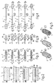
- the apparatus 1 comprises a pair of terminal cushion elements 2 (Figure 6A) which in the particular example described are defined by respective generally oblong solid bodies 3 of generally rectangular form, connected together by means of a cold-formable connection element defined by a biocompatible wire 4, preferably metal and of the type utilised in the field of dentistry.
- the wire 4 has respective terminal sections 5 embedded in the bodies 3, which in turn have various longitudinal dimensions so as to allow them to be fitted, in use, between the premolar and molar teeth (not illustrated) of the patient's dental arches or, alternatively, solely between the molar teeth (not illustrated) of the patient's dental arches.
- the bodies 3 are both made of biocompatible resilient material, preferably elastomeric material or, alternatively, by means of thermoplastic and/or thermosetting resins. Alternatively, however, the bodies 3 are made of a resilient material derived from a combination of the said resins with an elastomeric material. In all cases the bodies 3 have a high elasticity under load and, in particular, an elasticity such that following compression imparted by the patient's teeth they return to their undeformed condition without substantial residual plastic deformation.
- the bodies 3 are delimited by a lateral wall 6 and by two facial or contact walls 7 joined to the lateral walls 6 by rounded corners.
- the facial walls 7 are substantially parallel to one another and have a substantially rectangular shape and respective sides slightly curved with an outwardly facing convexity (Figures 1 and 6A) and are adapted, in use, to come into contact with the teeth (not illustrated) of the patient.
- the surfaces 7 are smooth; alternatively, however, as illustrated in Figure 5, they can have grooves or channels 8 extending parallel to or orthogonally of the major sides of the surfaces 7 ( Figures 5A, 5B) or, again, can have milled surfaces as illustrated in Figure 5C.
- one of the surfaces 7 is a convexly curved surface ( Figures 3D and 4E) or a concave surface ( Figure 3E); alternatively, in a variant not illustrated, both the surfaces 7 are curved surfaces having the same or different concavity from one another.
- bodies 3 each have a substantially trunco-pyramid form, and the respective contact surfaces 7 are inclined with respect to one another in such a way as to form between them a non-zero angle A; in particular the surfaces 7 can be inclined with respect to one another and converge towards an intermediate portion of the wire 4 as illustrated in Figure 3B or, alternatively, on the opposite side of the wire 4 ( Figure 3C) towards a free end of the associated body 3.
- the surfaces 7 of the same body 3 form between them an angle B and are convergent towards the other body 3 ( Figure 4C) or are convergent towards the outside ( Figure 4B) in such a way that the bodies 3 have respective larger ends facing one another.
- the surfaces 7 of the bodies again form an angle B with respect to one another, but the bodies 3 are connected to the wire 4 in such a way that the larger end of one of the bodies 3 is adjacent the smaller end of the other of the bodies 3.
- each body 3 has an elastic plate 9 embedded in it, which is preferably made of metal or, alternatively relatively rigid plastics material.
- each body 3 includes two portions 10 which in the particular case are of the same dimensions as one another and are connected to one another, for example via an adhesive material (not illustrated), or, alternatively, by heat welding.
- a relatively rigid plate 11 for example like the plate 9.
- each body 3 can have a regular parallelepiped form on a rectangular base (Figure 6B) or, alternatively, a kidney shape ( Figure 6D) or cylindrical shape ( Figure 6C).
- the cylindrical bodies 3 have respective axes 3A parallel to one another and substantially orthogonal to a plane in which the wire 4 lies; in a variant not illustrated the axes 3A of the cylindrical bodies extend in a direction substantially parallel to the said plane in which the wire 4 lies or, alternatively, form with this plane a predetermined non-zero angle.
- FIG. 7 relates to dental apparatus 13 similar to the apparatus 1 and in which component parts are distinguished where possible with the same reference numerals as the corresponding parts in the apparatus 1.
- the apparatus 13 includes a further intermediate element 14 which is coupled in a releasable manner to an intermediate section 15 of the wire 4 lying between the two terminal elements 2 and, in the particular example described, is defined by a single prismatic body 16 ( Figures 7, 8A, 8B) conveniently made of the same material as the bodies 3 and in the various different ways described for the production of the bodies 3.
- the body 16 can, in use, come into contact with the patient's incisor teeth (not illustrated) and it is also delimited by a lateral surface 17 and a pair of contact surfaces 18 which can be smooth or alternatively grooved or milled like the surfaces 7 of the bodies 3.
- the body 16 has the form of a circular sector, the smaller sides of which are curved with their convexity facing outwardly, and the corners of which are rounded.
- the said smaller sides are rectilinear and extend in respective substantially radial directions.
- the intermediate element 14 comprises a plurality of bodies 19 each of which has respective contact surfaces 20 which are disposed adjacent one another and are formed of the same material as that of the body 16.
- the bodies 19 are cylindrical bodies having the same dimensions as one another and respective axes substantially orthogonal to the plane in which the wire 4 lies.
- the cylindrical bodies 19 are positioned side by side and have different diameters from one another.
- the bodies 19 have a regular parallelepiped form and respective quadrilateral contact surfaces 20, in the specific case square, and are disposed with their sides (Figure 8D) or alternatively with their corners (Figure 8F) adjacent one another.
- the apparatus 1 and 13 described is first of all adapted to the dental arches (not illustrated) of the patient by cold shaping the wire 4 after which they are fitted between the dental arches by disposing the elements 2 and the element 4 when present between the corresponding teeth.
- the elements 2, 14 are clamped between the teeth and are either maintained in this position for a determined time or are squeezed by respective teeth with a predetermined pressure and frequency which depends on the ailment complained of by the patient or the therapy to which the patient is to be subjected in modifying the relative position of the dental arches.
- the apparatus 1 and 13 allows diagnosis and treatment of different types of ailments such as, for example, pathological occlusal pain, toothache of any cause, pathological pains in temperomandibular articulation, noises in the temperomandibular articulation itself reduced opening of the jaw, pain in the above mentioned articulation of muscular origin, disorders of swallowing and phonation, therapy of the orthodontic second class and false third class, headache of any origin, stiff neck of any origin, cervical pain and cervicobrachial pain, back pain, lumbar pain, sciatic pain, sea sickness, vertigo, brady acusia, problems of ocular accommodation and convergence, to rotate the shoulder gurdle or the pelvic girdle both for aesthetic purposes and for differential diagnosis in the occlusal-postural relationship and relative therapeutic indications.
- ailments such as, for example, pathological occlusal pain, toothache of any cause, pathological pains in temperomandibular articulation, noises in the temperomandibular
- the apparatus 1 and 13 described can be advantageously utilised in sport and in work and artistic activities to increase the articular excursion, muscular force, speed, strength, work, power, peripheral receptivity, coordination, attention, sensory acuity, performance, as well as for protection from contractions (cramps) and associated therapy and for the prevention of articular traumas.
- the apparatus 1 and 13 described as well as being extremely simple from the constructional point of view, has material advantages in use, which, as well as presenting a high elasticity under load, returns perfectly to their undeformed position immediately they are released. Therefore it is necessary to explain the fact that with respect to known apparatus in which the diagnostic and therapeutic effectiveness is attributed to the adaptability of the occlusal portions, in the apparatus 1 and 13 described this effectiveness is given by the occlusal non adaptability in that the cushion elements return perfectly to their undeformed condition after each clamping action by the patient.
- the apparatus 1 and 13 described is maintained in its operative equilibrium position solely by the actions exerted by the jaw and tongue muscles, always causing a different occlusion in the various cases and therefore always a different receptor response.
- the apparatus 1 and 13 described has extremely low manufacturing costs due to the fact that the materials utilised are readily available on the market at low cost.
- the terminal elements 2 can be different from one another and from the intermediate element 14 and could include several bodies different from one another both in shape and dimensions and, for example selectable from the different constructional shapes described.
- the cushion elements 2 and 14 can be made of different materials, and the bodies constituting the elements themselves can be defined by several parts not necessarily the same as one another in terms of shape and dimensions and material utilised.
- the intermediate element 14 comprises several bodies, all or only some of these bodies can be defined by several identical or different portions both as
- wire 4 could be replaced by an assembly of cold shapable wires disposed adjacent one another or slightly spaced from one another.
Landscapes
- Health & Medical Sciences (AREA)
- Oral & Maxillofacial Surgery (AREA)
- General Health & Medical Sciences (AREA)
- Otolaryngology (AREA)
- Physical Education & Sports Medicine (AREA)
- Dentistry (AREA)
- Epidemiology (AREA)
- Life Sciences & Earth Sciences (AREA)
- Animal Behavior & Ethology (AREA)
- Public Health (AREA)
- Veterinary Medicine (AREA)
- Dental Tools And Instruments Or Auxiliary Dental Instruments (AREA)
Claims (17)
- Zahnärztliche Vorrichtung (1; 13), die dafür vorgesehen ist, in die Mundhöhle eines Patienten eingesetzt zu werden, und die zwei terminale Kissenelemente (2), welche dafür vorgesehen sind, zwischen die Zähne des Patienten geklemmt zu werden, sowie Verbindungsmittel zur gegenseitigen Verbindung der Kissenelemente (2) umfaßt, dadurch gekennzeichnet, daß jedes terminale Kissenelement (2) durch einen zugehörigen festen elastischen Körper (3) definiert wird, der seitlich von einem Paar Kontaktflächen (7) begrenzt wird, die mit den Zähnen den Patienten in Kontakt kommen können; wobei die Verbindungsmittel ein Drahtelement (4) aus kaltverformbarem Material umfassen.
- Vorrichtung nach Anspruch 1, dadurch gekennzeichnet, daß sie außerdem ein dazwischenliegendes Kissenelement (14) einschließt, das sich zwischen den terminalen Kissenelementen (2) erstreckt und durch wenigstens einen weiteren elastischen Körper (16; 17) definiert wird, der seitlich von einem Paar Kontaktflächen (18; 20) begrenzt wird, die mit wenigstens einem Teil der Schneidezähne des Patienten in Kontakt kommen können; wobei der weitere elastische Körper (16; 19) an dem Drahtelement (4) befestigt ist.
- Vorrichtung nach Anspruch 2, dadurch gekennzeichnet, daß der weitere elastische Körper (16; 19) in einer lösbaren Weise an dem Drahtelement (4) befestigt ist.
- Vorrichtung nach Anspruch 2 oder Anspruch 3, dadurch gekennzeichnet, daß das dazwischenliegende Kissenelement (14) wenigstens zwei elastische Körper (19) umfaßt, die nebeneinander angeordnet und jeweils an dem Drahtelement (4) befestigt sind, wobei jeder der elastischen Körper (19) des dazwischenliegenden Kissenelementes (14) seitlich von zwei jeweiligen Kontaktflächen (20) begrenzt wird.
- Vorrichtung nach Anspruch 4, dadurch gekennzeichnet, daß alle elastischen Körper (3, 16, 19) aus elastomerem Material gefertigt sind.
- Vorrichtung nach Anspruch 4, dadurch gekennzeichnet, daß alle elastischen Körper (3, 16, 19) aus thermoplastischem Kunststoff gefertigt sind.
- Vorrichtung nach Anspruch 4, dadurch gekennzeichnet, daß alle elastischen Körper (3, 16, 19) aus duroplastischem Kunststoff gefertigt sind.
- Vorrichtung nach Anspruch 4, dadurch gekennzeichnet, daß jeder elastische Körper (3, 16, 19) wenigstens zwei miteinander verbundene Teile (10) umfaßt.
- Vorrichtung nach Anspruch 8, dadurch gekennzeichnet, daß wenigstens eines der Teile (10) zumindest teilweise aus elastomerem Material gefertigt ist.
- Vorrichtung nach einem der Ansprüche 4 bis 9, dadurch gekennzeichnet, daß wenigstens einer der elastischen Körper (3, 16, 19), welche die terminalen Kissenelemente (2) und das dazwischenliegende Kissenelement (14) bilden, eine elastische Platte (9, 11) enthält, die in dem elastischen Körper (3, 16, 19) eingebettet ist.
- Vorrichtung nach einem der Ansprüche 4 bis 10, dadurch gekennzeichnet, daß die Kontaktflächen (7, 18, 20) jedes elastischen Körpers (3, 16, 19) ebene Flächen sind, die im wesentlichen parallel zueinander sind.
- Vorrichtung nach einem der Ansprüche 4 bis 10, dadurch gekennzeichnet, daß die Kontaktflächen (7, 18, 20) jedes elastischen Körpers (3, 16, 19) im wesentlichen ebene Flächen sind und in Bezug aufeinander einen von Null verschiedenen Winkel (A, B, C) bilden.
- Vorrichtung nach einem der Ansprüche 4 bis 10, dadurch gekennzeichnet, daß wenigstens eine der Kontaktflächen (7, 18, 20) jedes elastischen Körpers (3, 16, 19) eine gekrümmte Fläche ist.
- Vorrichtung nach einem der Ansprüche 4 bis 13, dadurch gekennzeichnet, daß wenigstens eine der Kontaktflächen (7, 18, 20) jedes elastischen Körpers (3, 16, 19) eine gerillte Fläche ist.
- Vorrichtung nach einem der Ansprüche 4 bis 13, dadurch gekennzeichnet, daß wenigstens eine der Kontaktflächen (7, 18, 20) jedes elastischen Körpers (3, 16, 19) eine geriffelte Fläche ist.
- Vorrichtung nach einem der vorhergehenden Ansprüche, dadurch gekennzeichnet, daß das Drahtelement einen einzigen kaltverformbaren Draht (4) umfaßt.
- Vorrichtung nach Anspruch 16, dadurch gekennzeichnet, daß der Draht (4) ein Metalldraht ist.
Applications Claiming Priority (3)
| Application Number | Priority Date | Filing Date | Title |
|---|---|---|---|
| ITTO940071 IT232371Y1 (it) | 1994-04-12 | 1994-04-12 | Apparecchiatura dentale. |
| ITTO940071U | 1994-04-12 | ||
| PCT/IT1995/000051 WO1995027536A1 (en) | 1994-04-12 | 1995-04-10 | Dental apparatus |
Publications (2)
| Publication Number | Publication Date |
|---|---|
| EP0843580A1 EP0843580A1 (de) | 1998-05-27 |
| EP0843580B1 true EP0843580B1 (de) | 2000-10-04 |
Family
ID=11412122
Family Applications (1)
| Application Number | Title | Priority Date | Filing Date |
|---|---|---|---|
| EP95916831A Expired - Lifetime EP0843580B1 (de) | 1994-04-12 | 1995-04-10 | Dentalgerät |
Country Status (6)
| Country | Link |
|---|---|
| EP (1) | EP0843580B1 (de) |
| JP (1) | JPH09511423A (de) |
| AU (1) | AU2318295A (de) |
| DE (1) | DE69519043D1 (de) |
| IT (1) | IT232371Y1 (de) |
| WO (1) | WO1995027536A1 (de) |
Families Citing this family (7)
| Publication number | Priority date | Publication date | Assignee | Title |
|---|---|---|---|---|
| FR2855393B1 (fr) * | 2003-06-02 | 2006-02-17 | Bogumila Sobczak | Dispositif intra-oral auto-adaptable pour corriger l'asymetrie des articulations temporomandibulaires |
| JP5124772B2 (ja) * | 2007-03-30 | 2013-01-23 | 国立大学法人 岡山大学 | 咬みしめ抑制具 |
| EP2384717B1 (de) * | 2010-05-07 | 2018-07-11 | Falk Ifert | Vorrichtung zur kieferorthopädischen Zahnkorrektur und Verfahren zu ihrer Herstellung |
| JP5281046B2 (ja) * | 2010-07-02 | 2013-09-04 | 川上 和子 | 運動用マウスピース |
| JP5313979B2 (ja) * | 2010-08-26 | 2013-10-09 | 嘉則 佐藤 | 口腔周辺筋強化用マウスピース |
| KR101192539B1 (ko) * | 2012-05-24 | 2012-10-17 | 이상순 | 분할식 치열 교정장치 및 그 제조방법 |
| KR102107138B1 (ko) * | 2018-08-31 | 2020-05-07 | 오스템임플란트 주식회사 | 치아 교정 장치 |
Family Cites Families (4)
| Publication number | Priority date | Publication date | Assignee | Title |
|---|---|---|---|---|
| US3488848A (en) * | 1968-05-02 | 1970-01-13 | Martin D Lerman | Intra-oral corrective device |
| US4185817A (en) * | 1977-04-01 | 1980-01-29 | Peterson Eugenia N | Teeth exerciser |
| US4211008A (en) * | 1978-10-20 | 1980-07-08 | Lerman Martin D | Oral device |
| US4797093A (en) * | 1987-10-19 | 1989-01-10 | Bergersen Earl Olaf | Muscular expansion bumper and head-gear appliance |
-
1994
- 1994-04-12 IT ITTO940071 patent/IT232371Y1/it active IP Right Grant
-
1995
- 1995-04-10 DE DE69519043T patent/DE69519043D1/de not_active Expired - Lifetime
- 1995-04-10 EP EP95916831A patent/EP0843580B1/de not_active Expired - Lifetime
- 1995-04-10 JP JP7526225A patent/JPH09511423A/ja active Pending
- 1995-04-10 WO PCT/IT1995/000051 patent/WO1995027536A1/en not_active Ceased
- 1995-04-10 AU AU23182/95A patent/AU2318295A/en not_active Abandoned
Also Published As
| Publication number | Publication date |
|---|---|
| JPH09511423A (ja) | 1997-11-18 |
| EP0843580A1 (de) | 1998-05-27 |
| ITTO940071V0 (it) | 1994-04-12 |
| AU2318295A (en) | 1995-10-30 |
| IT232371Y1 (it) | 1999-12-17 |
| DE69519043D1 (de) | 2000-11-09 |
| ITTO940071U1 (it) | 1995-10-12 |
| WO1995027536A1 (en) | 1995-10-19 |
Similar Documents
| Publication | Publication Date | Title |
|---|---|---|
| AU2017254636B2 (en) | Apparatus and method for reducing bruxism and occlusal forces | |
| AU2002327075B2 (en) | Intraoral discluder device and method for preventing migraine and tension headaches and temporomandibular disorders | |
| US8439044B2 (en) | Dental appliance for minimizing effects of bruxism | |
| US20110151392A1 (en) | System of tube, resin and stops for orthodontics | |
| US20030015198A1 (en) | Method and device for addressing sleep apnea and related breathing disorders | |
| US7490609B2 (en) | Dental appliance for minimizing effects of bruxism | |
| KR102106213B1 (ko) | 치과교정술적 교정 장치 | |
| CN105377201A (zh) | 用于治疗磨牙症的牙科器具 | |
| JP2010538720A (ja) | 顔及び口の筋肉刺激器 | |
| EP0843580B1 (de) | Dentalgerät | |
| KR102800060B1 (ko) | 상악골 확장기 및 전인장치 | |
| WO2008023799A1 (fr) | Connecteur antérieur mandibulaire destiné à être placé dans la cavité orale afin de soulager le syndrome des apnées du sommeil ou le ronflement | |
| WO2015171495A1 (en) | Removable denture with metal denture tooth or teeth | |
| JPH05317335A (ja) | 顎関節の位置のずれを矯正する装置 | |
| US5938445A (en) | Kit for manufacturing occlusal plane raising plate | |
| KR101157506B1 (ko) | 치아교정 및 관리를 위한 구강내 압력측정용 감지센서 | |
| US5368477A (en) | Composite neuromuscular oral device | |
| KR102077947B1 (ko) | 슬림한 구조 기반의 턱관절 교합 안정화 장치 | |
| CN101181170A (zh) | 口腔功能矫治器 | |
| KR102257890B1 (ko) | 치아 교합력 전달장치 | |
| AU2021106195A4 (en) | An intra-oral appliance for use with a fixed retainer | |
| RU227381U1 (ru) | Ортодонтическое устройство в форме раковины | |
| JP5192474B2 (ja) | 口内刺激具 | |
| JPH0421528Y2 (de) | ||
| JP2025146922A (ja) | 整合間隙を伴うユーザカスタマイズ可能な整形外科整合デバイス |
Legal Events
| Date | Code | Title | Description |
|---|---|---|---|
| PUAI | Public reference made under article 153(3) epc to a published international application that has entered the european phase |
Free format text: ORIGINAL CODE: 0009012 |
|
| 17P | Request for examination filed |
Effective date: 19961108 |
|
| AK | Designated contracting states |
Kind code of ref document: A1 Designated state(s): BE DE ES FR GB NL |
|
| GRAG | Despatch of communication of intention to grant |
Free format text: ORIGINAL CODE: EPIDOS AGRA |
|
| 17Q | First examination report despatched |
Effective date: 19990820 |
|
| GRAG | Despatch of communication of intention to grant |
Free format text: ORIGINAL CODE: EPIDOS AGRA |
|
| GRAH | Despatch of communication of intention to grant a patent |
Free format text: ORIGINAL CODE: EPIDOS IGRA |
|
| GRAH | Despatch of communication of intention to grant a patent |
Free format text: ORIGINAL CODE: EPIDOS IGRA |
|
| GRAA | (expected) grant |
Free format text: ORIGINAL CODE: 0009210 |
|
| AK | Designated contracting states |
Kind code of ref document: B1 Designated state(s): BE DE ES FR GB NL |
|
| PG25 | Lapsed in a contracting state [announced via postgrant information from national office to epo] |
Ref country code: NL Free format text: LAPSE BECAUSE OF FAILURE TO SUBMIT A TRANSLATION OF THE DESCRIPTION OR TO PAY THE FEE WITHIN THE PRESCRIBED TIME-LIMIT Effective date: 20001004 Ref country code: FR Free format text: LAPSE BECAUSE OF FAILURE TO SUBMIT A TRANSLATION OF THE DESCRIPTION OR TO PAY THE FEE WITHIN THE PRESCRIBED TIME-LIMIT Effective date: 20001004 Ref country code: ES Free format text: THE PATENT HAS BEEN ANNULLED BY A DECISION OF A NATIONAL AUTHORITY Effective date: 20001004 Ref country code: BE Free format text: LAPSE BECAUSE OF FAILURE TO SUBMIT A TRANSLATION OF THE DESCRIPTION OR TO PAY THE FEE WITHIN THE PRESCRIBED TIME-LIMIT Effective date: 20001004 |
|
| REF | Corresponds to: |
Ref document number: 69519043 Country of ref document: DE Date of ref document: 20001109 |
|
| PG25 | Lapsed in a contracting state [announced via postgrant information from national office to epo] |
Ref country code: DE Free format text: LAPSE BECAUSE OF FAILURE TO SUBMIT A TRANSLATION OF THE DESCRIPTION OR TO PAY THE FEE WITHIN THE PRESCRIBED TIME-LIMIT Effective date: 20010105 |
|
| NLV1 | Nl: lapsed or annulled due to failure to fulfill the requirements of art. 29p and 29m of the patents act | ||
| EN | Fr: translation not filed | ||
| PG25 | Lapsed in a contracting state [announced via postgrant information from national office to epo] |
Ref country code: GB Free format text: LAPSE BECAUSE OF NON-PAYMENT OF DUE FEES Effective date: 20010410 |
|
| PLBE | No opposition filed within time limit |
Free format text: ORIGINAL CODE: 0009261 |
|
| STAA | Information on the status of an ep patent application or granted ep patent |
Free format text: STATUS: NO OPPOSITION FILED WITHIN TIME LIMIT |
|
| 26N | No opposition filed | ||
| GBPC | Gb: european patent ceased through non-payment of renewal fee |
Effective date: 20010410 |