EP0843392A2 - Akustooptisch abstimmbarer Laser - Google Patents
Akustooptisch abstimmbarer Laser Download PDFInfo
- Publication number
- EP0843392A2 EP0843392A2 EP97116907A EP97116907A EP0843392A2 EP 0843392 A2 EP0843392 A2 EP 0843392A2 EP 97116907 A EP97116907 A EP 97116907A EP 97116907 A EP97116907 A EP 97116907A EP 0843392 A2 EP0843392 A2 EP 0843392A2
- Authority
- EP
- European Patent Office
- Prior art keywords
- polarization
- aotf
- light
- port
- filter
- Prior art date
- Legal status (The legal status is an assumption and is not a legal conclusion. Google has not performed a legal analysis and makes no representation as to the accuracy of the status listed.)
- Withdrawn
Links
- 230000010287 polarization Effects 0.000 claims abstract description 104
- 239000013078 crystal Substances 0.000 claims description 7
- 239000013307 optical fiber Substances 0.000 claims description 7
- 230000008878 coupling Effects 0.000 claims 2
- 238000010168 coupling process Methods 0.000 claims 2
- 238000005859 coupling reaction Methods 0.000 claims 2
- 239000000835 fiber Substances 0.000 description 3
- 230000003287 optical effect Effects 0.000 description 3
- 230000001902 propagating effect Effects 0.000 description 2
- 239000000758 substrate Substances 0.000 description 2
- 230000000903 blocking effect Effects 0.000 description 1
- GQYHUHYESMUTHG-UHFFFAOYSA-N lithium niobate Chemical compound [Li+].[O-][Nb](=O)=O GQYHUHYESMUTHG-UHFFFAOYSA-N 0.000 description 1
- 230000004048 modification Effects 0.000 description 1
- 238000012986 modification Methods 0.000 description 1
- 238000010897 surface acoustic wave method Methods 0.000 description 1
Images

Classifications
-
- G—PHYSICS
- G02—OPTICS
- G02F—OPTICAL DEVICES OR ARRANGEMENTS FOR THE CONTROL OF LIGHT BY MODIFICATION OF THE OPTICAL PROPERTIES OF THE MEDIA OF THE ELEMENTS INVOLVED THEREIN; NON-LINEAR OPTICS; FREQUENCY-CHANGING OF LIGHT; OPTICAL LOGIC ELEMENTS; OPTICAL ANALOGUE/DIGITAL CONVERTERS
- G02F1/00—Devices or arrangements for the control of the intensity, colour, phase, polarisation or direction of light arriving from an independent light source, e.g. switching, gating or modulating; Non-linear optics
- G02F1/01—Devices or arrangements for the control of the intensity, colour, phase, polarisation or direction of light arriving from an independent light source, e.g. switching, gating or modulating; Non-linear optics for the control of the intensity, phase, polarisation or colour
- G02F1/11—Devices or arrangements for the control of the intensity, colour, phase, polarisation or direction of light arriving from an independent light source, e.g. switching, gating or modulating; Non-linear optics for the control of the intensity, phase, polarisation or colour based on acousto-optical elements, e.g. using variable diffraction by sound or like mechanical waves
- G02F1/125—Devices or arrangements for the control of the intensity, colour, phase, polarisation or direction of light arriving from an independent light source, e.g. switching, gating or modulating; Non-linear optics for the control of the intensity, phase, polarisation or colour based on acousto-optical elements, e.g. using variable diffraction by sound or like mechanical waves in an optical waveguide structure
-
- H—ELECTRICITY
- H01—ELECTRIC ELEMENTS
- H01S—DEVICES USING THE PROCESS OF LIGHT AMPLIFICATION BY STIMULATED EMISSION OF RADIATION [LASER] TO AMPLIFY OR GENERATE LIGHT; DEVICES USING STIMULATED EMISSION OF ELECTROMAGNETIC RADIATION IN WAVE RANGES OTHER THAN OPTICAL
- H01S3/00—Lasers, i.e. devices using stimulated emission of electromagnetic radiation in the infrared, visible or ultraviolet wave range
- H01S3/10—Controlling the intensity, frequency, phase, polarisation or direction of the emitted radiation, e.g. switching, gating, modulating or demodulating
- H01S3/106—Controlling the intensity, frequency, phase, polarisation or direction of the emitted radiation, e.g. switching, gating, modulating or demodulating by controlling devices placed within the cavity
- H01S3/1068—Controlling the intensity, frequency, phase, polarisation or direction of the emitted radiation, e.g. switching, gating, modulating or demodulating by controlling devices placed within the cavity using an acousto-optical device
Definitions
- the present invention relates to lasers, and more particularly, to lasers that can be tuned using acoustic-optical filters.
- Tunable lasers based on acousto-optic filters are known to the prior art. Basically, these lasers utilize AOTFs to select the wavelength of light that is amplified by the lasing element.
- An AOTF is an electronically tunable optical bandpass filter. Light traveling in a waveguide having a first polarization has its polarization rotated by an acoustic wave in a birefringent crystal in which the waveguide is constructed. The wavelength of the light whose polarization is rotated is determined by frequency of the acoustic wave. Hence, only light in a very narrow band has its polarization rotated. This light is selected by a polarization filter which passes light having the rotated polarization.
- Incident light outside of the band whose polarization is not rotated is blocked by this filter.
- the frequency of the light in the pass band is Doppler shifted by the acoustic wave.
- Prior art lasers based on AOTFs typically avoid this frequency shift, by including a second AOTF which rotates the polarization in the other direction, and hence, applies a Doppler shift that cancels the first Doppler shift.
- two AOTFs separated by a polarization filter must be constructed within the cavity.
- the need to provide such a double filter element substantially increases the cost of the laser.
- the two AOTFs must be identical to assure that complete cancellation of the Doppler shift provided by the first AOTF is achieved.
- the present invention is a tunable laser that includes a laser amplifier and an acousto-optic filter (AOTF).
- the AOTF includes a waveguide having first and second ports.
- a first polarization filter passes light of a first polarization state.
- the first polarization filter is located between the laser amplifier and the first port of the AOTF.
- the laser also includes a first asymmetrical polarization rotator located between the first port of the AOTF and the first polarization filter. The first asymmetrical polarization rotator rotates the polarization of light traveling from the first port of the AOTF to the first polarization filter by 90° while leaving unchanged the polarization of light traveling from the first polarization filter to the first port of the AOTF.
- a reflector reflects light leaving the second port of the AOTF back into the second port of the AOTF.
- a second polarization filter is located between the mirror and the second port of the AOTF. The second polarization filter passes light of a second polarization state which is orthogonal to the first polarization.
- a second asymmetrical polarization rotator is located between the second port of the AOTF and the second polarization filter. The second asymmetrical polarization rotator rotates the polarization of light traveling from the second polarization filter to the second port of the AOTF by 90° while leaving unchanged the polarization of light traveling from the second port of the AOTF to the second polarization filter.
- the teachings of the present invention may be applied to ring lasers and the like by including a walk-off crystal that laterally displaces the light leaving the first port of the AOTF relative to the light entering the first port.
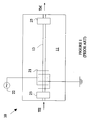
- Figure 1 is a schematic drawing of a typical AOTF.
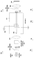
- Figure 2 is schematic drawing of a laser according to the present invention.
- Figure 3 is a schematic drawing of a second preferred embodiment of the present invention.
- AOTF 10 is fabricated in a crystalline substrate 11 such as lithium niobate.
- An optical waveguide 13 is formed in the upper surface of substrate 11.
- a surface acoustic wave is induced in the waveguide by a transducer 21 which is driven by signal generator 22.
- the frequency of the acoustic wave is determined by the frequency of the signal from generator 22.
- the acoustic wave generates a diffraction grating in the waveguide.
- the grating couples the transverse electric (TE) and transverse magnetic (TM) polarization modes of the light within the narrow band of frequencies corresponding to the diffraction grating spacing. Within this narrow band, light propagating in one polarization mode is converted to the orthogonal polarization mode. The polarization of the light outside of this band is not converted.
- the rotation of the plane of polarization of the light in the narrow band is used to construct a filter that passes only light in this narrow band by utilizing two polarization filters at the ends of the waveguide.
- a TE pass polarization filter 23 at one end of the waveguide blocks any light that is not in the TE mode from entering the waveguide.
- a light signal including light within the band of interest having a TE polarization is applied to this filter.
- the polarization of the light within the band of interest leaving the waveguide will have been rotated to the TM mode.
- a TM pass polarization filter 25 at the other end of the waveguide allows this light to pass while blocking light in the TE mode. Hence, light outside of the narrow band of interest is blocked.
- the frequency of the light is Doppler-shifted because the grating induced by the acoustic wave is in motion with respect to the waveguide.
- Light propagating in the direction from filter 23 to filter 25 will be downshifted or upshifted in frequency depending on the direction of travel of the light relative to the direction of motion of the acoustic wave.
- this frequency shift causes problems in applications in which the AOTF is used to construct a laser.
- One prior art solution to this problem is to include a second AOTF in which the light propagates in the opposite direction with respect to the acoustic wave thereby causing an upshifting of the light frequency that cancels the downshift.
- the second AOTF must be identical to the first AOTF. This requirement significantly increases the cost of a laser utilizing this type of tunable filter.
- FIG. 2 is a schematic drawing of a tunable laser 100 according to the present invention.
- Light leaving laser amplifier 112 is focused into an input port of AOTF 110 after passing through a polarizer 123 and a first asymmetrical polarization rotator 154 whose function will be discussed in more detail below.
- the light leaving AOTF 110 passes through a second asymmetrical polarization rotator 155 and a polarizer 153.
- the light leaving polarizer 153 is reflected by a reflector 141 which reverses the direction of travel of the light and images the reflected light back into port 186 of AOTF 110 after passing through polarizer 153 and second asymmetrical polarization rotator 155.
- the light leaving port 185 of AOTF passes through first asymmetrical polarization rotator 154 and polarizer 123 prior to being imaged into laser amplifier 112 by lens 111.
- the amplified light signal is reflected back into laser amplifier 112 by mirror 130.
- the present invention utilizes first and second asymmetrical polarization rotators shown at 154 and 155, respectively. These rotators rotate the polarization of the light in a manner that depends on the direction of travel of the light through the rotator. In one direction, the polarization remains unchanged, and in the other direction, the polarization is rotated by 90° thereby converting TM polarized light to TE polarized light, and vice versa.
- the asymmetrical polarization rotators are constructed from a 45° Faraday rotator and a half-wave plate, as shown at 133 and 125, respectively.
- the Faraday rotator rotates the direction of polarization by 45° in a direction that depends on the direction of travel of the light relative to the magnetic field in the Faraday rotator.
- the half-wave plate has its optical axis set at 22.5° with respect to the TM or TE polarization direction.
- the half-wave plate rotates the direction of polarization of the light by 45° in a direction that is independent of the direction of travel of the light.
- the 45° rotation provided by the Faraday rotator adds to the 45° rotation provided by the half-wave plate to generate a 90° rotation of the polarization.
- the 45° rotation provided by the Faraday rotator cancels the 45° rotation provided by the half-wave plate leaving the direction of polarization unchanged.
- TM polarized light leaving laser amplifier 112 in the direction of AOTF 110 is TM polarized.
- Lens 111 focuses the light leaving amplifier 112 into the first port 185 of the waveguide of AOTF 110.
- this light passes through a TM polarizer 123 and first asymmetrical polarization rotator 154.
- Asymmetrical polarization rotator 154 is configured such that the polarization of the light passing in the direction from laser amplifier 112 to AOTF 110 is unchanged; hence, the light entering AOTF 110 is TM polarized.
- Light in a band determined by the frequency of oscillator 113 is converted to TE polarized light and Doppler downshifted or upshifted in frequency.
- This light leaves AOTF 110 through a second port 186 and passes through the second asymmetrical polarization rotator 155.
- Asymmetrical polarization rotator 155 is configured such that the polarization of light leaving AOTF 110 is not altered.
- the light leaving rotator 155 passes through a TE polarizer 153 which eliminates any light having a frequency outside of the frequency band of interest, i.e., the remaining light that is still TM polarized.
- the light leaving TE polarizer 153 is then reflected from a reflector 141 comprising mirror 120 and lens 112 and imaged back into AOTF 110.
- a concave mirror may alternatively be used as the reflector 141.
- This light is still TE polarized; hence, it passes through TE polarizer 153 and then through rotator 155 before entering the second port of the waveguide of AOTF 110.
- the polarization of the light is rotated 90° by rotator 155; thus, the light entering AOTF 110 is now TM polarized.
- the polarization of the light in the narrow band of interest will be rotated to TE by AOTF 110 and the frequency of that light will be Doppler upshifted or downshifted by an amount exactly equal to the Doppler downshift or upshift, respectively, experienced by the light in traversing AOTF in the opposite direction.
- the light leaving AOTF 110 in the frequency band of interest will be TE polarized.
- the first asymmetrical polarization rotator 154 will convert this light to the TM polarization, and TM polarizer 123 will block the light outside of the frequency band of interest, since that light will now be TE polarized.
- the light leaving polarizer 123 is imaged back into laser amplifier 112 by lens 111.
- Light leaving laser amplifier 112 is reflected back toward AOTF 110 by mirror 130.
- Light may be outputted from laser 100 by making either mirror 120 or mirror 130 partially reflecting.
- mirror 130 is part of laser amplifier 112
- mirror 120 is the partially reflecting mirror.
- polarizers, rotators and AOTF have been shown spaced apart in Figure 2 to simplify the above description. However, it should be noted that in the preferred embodiment of the present invention, these components are in contact.
- the rotators and polarizers are preferably attached to the ends of AOTF 110 to form a single assembly.
- FIG. 3 illustrates the manner in which the present invention may be utilized in a ring laser in which the lasing amplifier is connected by input and output polarization maintaining fibers 201 and 202, respectively.
- elements shown in Figure 3 that serve the same functions as elements shown in Figure 2 have been given labels that differ from the corresponding elements in Figure 2 by 100. These elements will not be discussed in detail here.
- the arrangement shown in Figure 3 includes a walk-off crystal 205 which is oriented such that its walk-off direction results in light of one polarization being displaced laterally with respect to the axis of optical fiber 201.
- a light beam entering walk-off crystal 205 will be displaced laterally by an amount that depends on the polarization of the light.
- the system is configured such that TM polarized light arriving via input fiber 201 is imaged into AOTF 210. This light is processed by AOTF 210 and the components following it and leaves port 285 as TE polarized light.
- Walk-off crystal 205 displaces this TE polarized light by an amount sufficient to image the light into output fiber 202.
- the TE polarized light is converted back to TM polarized light by asymmetrical polarization rotator 254.
Landscapes
- Physics & Mathematics (AREA)
- Electromagnetism (AREA)
- Optics & Photonics (AREA)
- Nonlinear Science (AREA)
- Engineering & Computer Science (AREA)
- Plasma & Fusion (AREA)
- General Physics & Mathematics (AREA)
- Lasers (AREA)
- Optical Modulation, Optical Deflection, Nonlinear Optics, Optical Demodulation, Optical Logic Elements (AREA)
Applications Claiming Priority (2)
| Application Number | Priority Date | Filing Date | Title |
|---|---|---|---|
| US751137 | 1996-11-15 | ||
| US08/751,137 US5724373A (en) | 1996-11-15 | 1996-11-15 | Microphotonic acousto-optic tunable laser |
Publications (2)
| Publication Number | Publication Date |
|---|---|
| EP0843392A2 true EP0843392A2 (de) | 1998-05-20 |
| EP0843392A3 EP0843392A3 (de) | 1998-10-28 |
Family
ID=25020650
Family Applications (1)
| Application Number | Title | Priority Date | Filing Date |
|---|---|---|---|
| EP97116907A Withdrawn EP0843392A3 (de) | 1996-11-15 | 1997-09-29 | Akustooptisch abstimmbarer Laser |
Country Status (3)
| Country | Link |
|---|---|
| US (1) | US5724373A (de) |
| EP (1) | EP0843392A3 (de) |
| JP (1) | JPH10190116A (de) |
Cited By (2)
| Publication number | Priority date | Publication date | Assignee | Title |
|---|---|---|---|---|
| WO2012079412A1 (zh) * | 2010-12-14 | 2012-06-21 | 华为技术有限公司 | 外腔激光器和波分复用无源光网络系统 |
| US9507069B2 (en) | 2014-12-19 | 2016-11-29 | The United States Of America As Represented By The Secretary Of The Army | Polarization hyperspectral/multispectral imager and method |
Families Citing this family (23)
| Publication number | Priority date | Publication date | Assignee | Title |
|---|---|---|---|---|
| JP3421194B2 (ja) * | 1996-04-30 | 2003-06-30 | 理化学研究所 | 波長可変レーザーにおける波長選択可能なレーザー発振装置 |
| DE69835216T2 (de) | 1997-07-25 | 2007-05-31 | Nichia Corp., Anan | Halbleitervorrichtung aus einer nitridverbindung |
| JP3779054B2 (ja) | 1998-01-23 | 2006-05-24 | 富士通株式会社 | 可変光学フィルタ |
| JP3638777B2 (ja) | 1998-02-04 | 2005-04-13 | 富士通株式会社 | 利得等化のための方法並びに該方法の実施に使用する装置及びシステム |
| JP3770014B2 (ja) | 1999-02-09 | 2006-04-26 | 日亜化学工業株式会社 | 窒化物半導体素子 |
| KR100683875B1 (ko) * | 1999-03-04 | 2007-02-15 | 니치아 카가쿠 고교 가부시키가이샤 | 질화물 반도체 레이저소자 |
| US6246816B1 (en) * | 1999-07-30 | 2001-06-12 | Litton Systems, Inc. | Wavelength stabilized laser light source |
| US6570894B2 (en) | 2001-01-30 | 2003-05-27 | Tektronix, Inc. | Real-time wavelength calibration for swept lasers |
| US6959024B2 (en) * | 2002-02-28 | 2005-10-25 | Picarro, Inc. | Laser Tuning by spectrally dependent spatial filtering |
| JP2003270604A (ja) * | 2002-03-18 | 2003-09-25 | Fujitsu Ltd | 波長制御光装置及び光制御方法 |
| US6847662B2 (en) * | 2002-03-25 | 2005-01-25 | Fujitsu Limited | Wavelength-selectable laser capable of high-speed frequency control |
| JP4059779B2 (ja) * | 2002-06-14 | 2008-03-12 | 富士通株式会社 | 波長選択装置、波長選択レーザおよび波長可変レーザ |
| US7382360B2 (en) * | 2003-04-15 | 2008-06-03 | Synaptics Incorporated | Methods and systems for changing the appearance of a position sensor with a light effect |
| US7061618B2 (en) | 2003-10-17 | 2006-06-13 | Axsun Technologies, Inc. | Integrated spectroscopy system |
| US7197208B2 (en) * | 2004-04-13 | 2007-03-27 | Agilent Technologies | Wavelength tunable light sources and methods of operating the same |
| US20060050747A1 (en) * | 2004-09-08 | 2006-03-09 | Trutna William R Jr | Frequency-tunable light sources and methods of generating frequency-tunable light |
| US8347373B2 (en) | 2007-05-08 | 2013-01-01 | Fortinet, Inc. | Content filtering of remote file-system access protocols |
| TWI362769B (en) * | 2008-05-09 | 2012-04-21 | Univ Nat Chiao Tung | Light emitting device and fabrication method therefor |
| US8526472B2 (en) | 2009-09-03 | 2013-09-03 | Axsun Technologies, Inc. | ASE swept source with self-tracking filter for OCT medical imaging |
| US8670129B2 (en) | 2009-09-03 | 2014-03-11 | Axsun Technologies, Inc. | Filtered ASE swept source for OCT medical imaging |
| CN102299472B (zh) * | 2011-07-12 | 2012-11-21 | 天津奇谱光电技术有限公司 | 光频率精密可调谐激光器 |
| CN103944048B (zh) * | 2014-04-23 | 2017-08-25 | 北京大学 | 一种基于单包层钕光纤及环形腔的飞秒激光器及制作方法 |
| US9160136B1 (en) * | 2014-05-30 | 2015-10-13 | Lee Laser, Inc. | External diffusion amplifier |
Family Cites Families (8)
| Publication number | Priority date | Publication date | Assignee | Title |
|---|---|---|---|---|
| US4736382A (en) * | 1987-01-20 | 1988-04-05 | Hughes Aircraft Company | Acousto-optical laser isolator |
| US4852106A (en) * | 1987-02-19 | 1989-07-25 | Brother Kogyo Kabushiki Kaisha | Optical system for producing controlled beat frequency |
| GB2215074A (en) * | 1988-02-17 | 1989-09-13 | Gen Electric Co Plc | Acousto-optic tunable filter |
| US4975918A (en) * | 1989-06-07 | 1990-12-04 | Maxwell Laboratories, Inc. | Tunable laser |
| US5140599A (en) * | 1990-08-01 | 1992-08-18 | Hewlett-Packard Company | Optical oscillator sweeper |
| US5263037A (en) * | 1990-08-01 | 1993-11-16 | Hewlett-Packard Company | Optical oscillator sweeper |
| US5390204A (en) * | 1992-09-25 | 1995-02-14 | Incisive Technologies, Inc. | Intracavity modulated pulsed laser with a variably controllable modulation frequency |
| US5452314A (en) * | 1994-08-01 | 1995-09-19 | Hewlett-Packard Company | Controllable-birefringence, acousto-optic tunable filter and a laser tuned by the same |
-
1996
- 1996-11-15 US US08/751,137 patent/US5724373A/en not_active Expired - Lifetime
-
1997
- 1997-09-29 EP EP97116907A patent/EP0843392A3/de not_active Withdrawn
- 1997-11-17 JP JP9314986A patent/JPH10190116A/ja active Pending
Non-Patent Citations (3)
| Title |
|---|
| BOYD G D ET AL: "Tunable acoustooptic reflection filters in LiNbO/sub 3/ without a Doppler shift" JOURNAL OF LIGHTWAVE TECHNOLOGY, APRIL 1989, USA, vol. 7, no. 4, pages 625-631, XP000032973 ISSN 0733-8724 * |
| SMITH D A ET AL: "Acoustically tuned erbium-doped fiber ring laser" OPTICS LETTERS, 15 MARCH 1991, USA, vol. 16, no. 6, pages 387-389, XP000176156 ISSN 0146-9592 * |
| SMITH D A ET AL: "Integrated-optic acoustically tunable reflection filter" OPTICS LETTERS, 1 NOV. 1989, USA, vol. 14, no. 21, pages 1240-1242, XP000080708 ISSN 0146-9592 * |
Cited By (2)
| Publication number | Priority date | Publication date | Assignee | Title |
|---|---|---|---|---|
| WO2012079412A1 (zh) * | 2010-12-14 | 2012-06-21 | 华为技术有限公司 | 外腔激光器和波分复用无源光网络系统 |
| US9507069B2 (en) | 2014-12-19 | 2016-11-29 | The United States Of America As Represented By The Secretary Of The Army | Polarization hyperspectral/multispectral imager and method |
Also Published As
| Publication number | Publication date |
|---|---|
| EP0843392A3 (de) | 1998-10-28 |
| US5724373A (en) | 1998-03-03 |
| JPH10190116A (ja) | 1998-07-21 |
Similar Documents
| Publication | Publication Date | Title |
|---|---|---|
| US5724373A (en) | Microphotonic acousto-optic tunable laser | |
| US5611004A (en) | Microphotonic polarization independent acousto optical tunable filter and receiver | |
| CA2004998C (en) | Integrated acousto-optic filters and switches | |
| US5579420A (en) | Optical filter | |
| US5329397A (en) | Acousto-optic tunable filter | |
| US5430454A (en) | Device for creating optical delays and application to an optical control system for a scanning antenna | |
| US5652809A (en) | Offset rotated transducers for acousto-optical tunable filters | |
| US6982818B2 (en) | Electronically tunable optical filtering modules | |
| US3944334A (en) | Acousto-optic filter | |
| US5909304A (en) | Acousto-optic tunable filter based on isotropic acousto-optic diffraction using phased array transducers | |
| US5936768A (en) | Optical passive device for an optical fiber amplifier and the optical amplifier | |
| EP0488211B1 (de) | Polarisationsunabhängige optische Vorrichtung | |
| GB2109122A (en) | Acousto-optic isolator | |
| US4720177A (en) | Tunable acousto-optic filter utilizing internal mode conversion | |
| Cheng et al. | Baseband integrated acousto‐optic frequency shifter | |
| JPH0283523A (ja) | 光アイソレータ | |
| US5734494A (en) | Wavelength conversion device and wavelength conversion method | |
| Molchanov et al. | Quasi-collinear tunable acousto-optic paratellurite crystal filters for wavelength division multiplexing and optical channel selection | |
| US3740117A (en) | Acousto-optic filter having an increased optical beam aperture | |
| CA2133556A1 (en) | Improvements to optical phase shifting | |
| US6091865A (en) | Irreversible optical device utilizing optical frequency shift | |
| US4896949A (en) | Acousto-optic tunable bandpass filter with strong sideband suppression | |
| US4558926A (en) | Acousto-optic beam deflector | |
| JP2975497B2 (ja) | インライン型光アイソレータ | |
| JPH10246875A (ja) | 音響光学変調器 |
Legal Events
| Date | Code | Title | Description |
|---|---|---|---|
| PUAI | Public reference made under article 153(3) epc to a published international application that has entered the european phase |
Free format text: ORIGINAL CODE: 0009012 |
|
| AK | Designated contracting states |
Kind code of ref document: A2 Designated state(s): AT BE CH DE DK ES FI FR GB GR IE IT LI LU MC NL PT SE |
|
| AX | Request for extension of the european patent |
Free format text: AL;LT;LV;RO;SI |
|
| PUAL | Search report despatched |
Free format text: ORIGINAL CODE: 0009013 |
|
| AK | Designated contracting states |
Kind code of ref document: A3 Designated state(s): AT BE CH DE DK ES FI FR GB GR IE IT LI LU MC NL PT SE |
|
| AX | Request for extension of the european patent |
Free format text: AL;LT;LV;RO;SI |
|
| AKX | Designation fees paid | ||
| STAA | Information on the status of an ep patent application or granted ep patent |
Free format text: STATUS: THE APPLICATION IS DEEMED TO BE WITHDRAWN |
|
| 18D | Application deemed to be withdrawn |
Effective date: 19990429 |
|
| REG | Reference to a national code |
Ref country code: DE Ref legal event code: 8566 |