BACKGROUND OF THE INVENTION
The invention relates to a multibeam antenna which is used for
receiving micro waves from plural geostationary satellites.
Recently, many geostationary broadcasting satellites and
geostationary communication satellites have been launched. The need for
receiving micro waves from, for example, two adjacent satellites by using a
single antenna and selectively using one of the received micro waves is
increasing.
Conventionally, a multibeam antenna which receives micro waves
from plural satellites is configured so that micro waves from plural satellites
are reflected and focused by a single parabola reflector and the focused satellite
signals respectively enter different primary radiators.
Horn type primary radiators (or feedhorns) are used as the primary
radiators. When two satellite micro waves are to be received, for example, two
horn type primary radiators are supported by an arm so as to be placed at the
reflection and focusnce position of the parabola reflector. The elevation angles
for the satellites with respect to the ground are different from each other.
Furthermore, the degree of the difference in elevation angle is varied
depending on the receiving areas. For each receiving area, therefore, the
inclination of the horn arrangement of the primary radiators with respect to an
axis which is in parallel with the ground must be adjusted.
Hereinafter, the inclination of the horn arrangement of primary
radiators with respect to an axis which is in parallel with the ground is referred
to as the inclination angle.
In the case where satellite signals to be received are linearly
polarized, the inclination of each incident micro wave with respect to the
ground is changed depending on the satellites and receiving areas. For each
receiving area, therefore, the reception polarization angle of each primary
radiator must be adjusted.
When the direction of the conventional multibeam antenna for
linearly polarized waves is to be adjusted, therefore, the arrangement
inclination angles of primary-radiator horns with respect to each satellite, and
the reception polarization angles of primary radiators must be adjusted in
accordance with the receiving area. This produces problems in that a
mechanism for adjusting the angles is complicated in structure, and that the
adjusting work is cumbersome.
Conventionally, a flaring horn type primary radiator is usually used
as a primary radiator of an antenna for satellite broadcasting. Even when a
parabola reflector has a small diameter of, for example, 45 cm ⊘, the
arrangement distance among the primary radiators can be sufficiently made
large as far as adjacent satellites from which micro waves are to be received are
separated from each other by an elongation of about 8 deg. Consequently,
flaring horns of primary radiators can be adjacently arranged without
interfering with each other. By contrast, in the case where adjacent satellites
from which micro waves are to be received are separated from each other by a
small elongation of 4 deg., the arrangement distance among the primary
radiators is as small as about 25 mm. As a result, when such flaring horn type
primary radiators are used, the radiator horns interfere or contact with each
other and hence it is impossible to constitute a multibeam antenna, thereby
producing a problem in that plural antennas respectively for satellites from
which micro waves are to be received must be installed.
As discussed above, in a primary radiator of a 45-cm ⊘ dual-beam
antenna system which receives micro waves of the 12 GHz band from two
satellites of an elongation of 4 deg., for example, the horn interval is about 25
mm. When a primary radiator of such an antenna is configured by a usual
flare horn as shown in Figs. 22(A) and 22(B), the aperture diameter is about 30
mm. Therefore, the antenna cannot be structurally configured. In order to
realize such an antenna system, it is required to set the aperture diameter of a
primary radiator to be 25 mm or less. In a circular waveguide designated as
WCI-120 in EIAJ (Standard of Electronic Industries Association of Japan), the
inner diameter of the waveguide is 17.475 mm. When such a waveguide is
used, therefore, the horn has substantially a flare angle of about 0 deg. in
consideration of the production process of an actual product. In other words,
the horn has a circular waveguide section aperture as shown in Figs. 23(A) and
23(B).
Fig. 22(A) is a front view of the conventional flare horn type primary
radiator, and Fig. 22(B) is a section view taken along the line A-A' of Fig. 22(A).
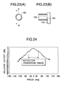
Fig. 23(A) is a front view of a conventional circular waveguide type primary
radiator, and Fig. 23(B) is a section view taken along the line A-A' of Fig. 23(A).
In Fig. 22(A) and 22(B), 131 designates a flared waveguide which is
disposed on a substrate 132. A feeding point 133 is configured by a printed
circuit formed on the substrate 132, so as to be positioned at the center of the
bottom face of the flared waveguide 131.
The circular waveguide type primary radiator shown in Figs. 23(A)
and 23(B) is a circular waveguide 135 in place of the flared waveguide 131.
The other components are configured in the same manner as those of the flare
horn type primary radiator of Fig. 22(A).
Fig. 24 shows the radiational pattern of the circular waveguide type
primary radiator. In the case where the reflector is offset, the radiation angle
of the primary radiator is about 40 deg. In the directional pattern of Fig. 24,
the leakage power is large in the reflector irradiation, and the unevenness of
the electric field in the reflector irradiation range is large. Therefore, the
antenna gain is lowered.
Methods such as that in which the horn aperture diameter is reduced,
that in which a helical antenna is used with supplying a power through a
coaxial system, and that in which a traveling-wave type antenna such as a
circular waveguide feed poly-rod antenna is used as a primary radiator may be
used as means for solving the problems discussed above. In the conventional
multibeam antenna, moreover, received-signal cables extending from
converters for primary radiators are connected to an external switching device,
and one satellite broadcasting program which is to be received is selected by
controlling the switching operation of the switching device. This configuration
involves problems in that the user must purchase such an external switching
device, and that a wiring work and the like are required.
When an integral converter is configured by using plural primary
radiators, substrate-printed probes 202 are formed on a single substrate 201 as
shown in Fig. 29, and all other circuits also are disposed on the substrate 201.
Each of the substrate-printed probes 202 comprises a horizontally-polarized-wave
probe 202a and a vertically-polarized-wave probe 202b. The substrate-printed
probes 202 are disposed in power feeding portions of plural (for example,
two) primary radiator apertures 203, respectively. Signals output from the
horizontally-polarized-wave probe 202a and the vertically-polarized-wave
probe 202b are amplified by high- frequency amplifiers 203a and 203b, and then
subjected to selection by horizontal/ vertical changeover switches 204a and 204b.
Signals which are selected by the horizontal/ vertical changeover switches
204a and 204b are then subjected to further selection by a satellite changeover
switch 205. The selected signal is amplified by a high-frequency amplifier 206,
and then supplied to a frequency converter 207. The oscillation output of a
local oscillator 208 is supplied to the frequency converter 207. The frequency
converter 207 outputs, as an intermediate-frequency signal, a signal of a
frequency which is equal to the difference in frequency between the signal from
the high-frequency amplifier 206 and that from the local oscillator 208. The
signal output from the frequency converter 207 is amplified by an
intermediate-frequency amplifier 209. The amplified signal is supplied to the
outside through a terminal 210.
The conventional multibeam antenna has problems in that the
arrangement inclination angles of primary radiators must be respectively
adjusted, and that the reception polarization angles of the primary radiators
must be respectively adjusted.
The conventional multibeam antenna has a further problem in that,
in the case where satellites from which micro waves are to be received are
separated from each other by a small distance of, for example, 4 deg., flaring
horn type primary radiators which are adjacently arranged contact or interfere
with each other and therefore cannot constitute a multibeam antenna.
The conventional multibeam antenna has a further problem in that,
in order to selectively receive a desired satellite broadcasting program, an
external switching device, wirings for the device, and the like are required.
Furthermore, in the conventional primary radiator, a current
supplied from a feeding point flows into a rear side through an edge portion of a
horn aperture or that of a ground plane of a helical antenna, thereby causing
the primary radiator to have radiational patterns in which radiation other than
that to a reflector is large. As a result, the antenna gain is lowered.
When micro waves from plural satellites are to be received by the
conventional converter for receiving micro waves from satellites, the substrate-printed
probes 202 are set so that an axis which is in parallel with the ground
in each area, the orbit inclinations of the objective satellites, and the
polarization angles of the satellites coincide with each other. In this case, the
converter is dedicated to the satellites from which micro waves are to be
received. When converters corresponding to all satellites are to be produced,
therefore, the converters cannot entirely share substrates, with the result that
the productivity is impaired and hence the production cost of a converter is
increased.
SUMMARY OF THE INVENTION
The invention has been conducted in view of these problems. It is a
first object of the invention to provide a multibeam antenna in which the
arrangement inclination angle of primary radiators and the reception
polarization angle can be easily adjusted.
It is a second object of the invention to provide a multibeam antenna
in which, even in the case where satellites from which micro waves are to be
received are separated from each other by a small elongation of, for example, 4
deg., horns of primary radiators do not interfere nor contact with each other,
and a configuration for receiving multibeams can be constituted.
It is a third object of the invention to provide a multibeam antenna in
which a desired satellite broadcasting program can be easily selected so as to be
received, without requiring an external switching device, wirings, and the like
to be disposed.
It is a fourth object of the invention to provide a primary radiator of a
small gain reduction in a small-diameter multibeam antenna for a small
separation, and a converter for receiving micro waves from satellites with
which a primary radiator is integrated.
It is a fifth object of the invention to provide a converter for receiving
micro waves from satellites which, even when micro waves from plural
satellites are to be received, can use a common substrate, so that the
productivity is improved and hence the production cost can be reduced.
According to a first aspect of the invention, there is provided a
multibeam antenna comprise: a reflector which reflects and focuses micro
waves from plural satellites; plural horn type primary radiators which receive
the plural satellite micro waves which are reflected and focused by the reflector,
respectively; a converter to which the plural horn type primary radiators are
adjacently integrally attached, and which converts and amplifies satellite
signals respectively received by the primary radiators; probes respectively for
the primary radiators, the probes being arranged at an angle difference
corresponding to a difference in polarization angle among the plural satellites
under a state where the plural primary radiators are attached to the converter;
a radiator supporting arm which supports the converter so that horns of the
plural primary radiators are oriented to a direction of reflection of the reflector;
and a rotation mechanism which is disposed between the radiator supporting
arm and the converter, and which adjusts a rotation position of the converter so
that an arrangement inclination angle of the primary radiators with respect to
an axis which is in parallel with a ground, the arrangement inclination angle of
the plural primary radiators, and a reception polarization angle of each of the
radiators being simultaneously adjusted by the rotation mechanism.
According to a second aspect of the invention, there is provided the
multibeam antenna of the first aspect wherein, the primary radiator is a
circular waveguide aperture horn, and a dielectric part is attached to an
aperture of the horn.
According to a third aspect of the invention, there is provided the
multibeam antenna of the first or second aspect further comprising receiving
satellite switching means for, in accordance with external instructions,
selecting one of the plural satellite signals received by the plural primary
radiators, and outputting the selected signal.
According to a fourth aspect of the invention, there is provided a
primary radiator of an antenna for receiving micro waves from satellites
comprising: two or more primary radiator apertures which are juxtaposed with
maintaining predetermined intervals; and at least one choke which is
commonly disposed on outer peripheries of the plural apertures, the choke
having a depth of about one quarter of a wavelength.
According to this configuration, the edge portion of the aperture face
has theoretically an infinite impedance, and hence a current which rearward
flows from the edge portion of the aperture face can be suppressed, thereby
preventing radiation toward the rear side of the primary radiator from
occurring. Therefore, micro waves from plural satellites can be efficiently
received.
According to a fifth aspect of the invention, there is provided a
converter for receiving micro waves from satellites which integrated with two
or more primary radiator apertures for receiving micro waves transmitted from
two or more satellites by means of an antenna, and which comprises: a
substrate on which a converter circuit portion is formed; substrate-printed
probe substrates which respectively correspond to the primary radiator
apertures, and which are rotatably disposed on and independently from the
substrate; and substrate-printed probes which are respectively disposed on the
substrate-printed probe substrates, and which are connected to the converter
circuit portion, a rotation angle of each of the substrate-printed probe
substrates being able to be set in accordance with the satellites.
Each of the substrate-printed probes comprises a horizontally-polarized-wave
probe and a vertically-polarized-wave probe, and the converter
circuit portion comprises first switching means for switching over the
horizontally-polarized-wave probe and the vertically-polarized-wave probe, and
second switching means for switching over the substrate-printed probes.
In the invention, a converter for receiving micro waves from
satellites which is integrated with two or more primary radiator apertures for
receiving micro waves transmitted from two or more satellites by means of an
antenna comprises: a substrate on which a converter circuit portion is formed; a
first substrate-printed probe which corresponds to one of the primary radiator
apertures that is used for receiving a micro wave from one of the satellites, and
which is disposed on the substrate; substrate-printed probe substrates which
respectively correspond to the other one or more primary radiator apertures,
and which are rotatably disposed on and independently from the substrate; one
or more second substrate-printed probes which are respectively disposed on the
substrate-printed probe substrates; and switching means for switching over the
first and second substrate-printed probes, the switching means being disposed
in the converter circuit portion.
According to this configuration, the converter can be easily made
coincident with the polarization angles of plural satellites, and the inclination
angle which is the angle difference between an axis which is in parallel with
the ground and the axis of the satellite orbit. Even when the polarization
angles of adjacent two satellites are changed or when a satellite from which a
micro wave is to be received is changed to another one, therefore, the converter
can be easily made coincident with the polarization angle. Furthermore, the
use of a common circuit can reduce the production cost.
BRIEF DESCRIPTION OF THE DRAWINGS
Figs. 1(A), 1(B) and 1(C) are side, front and top views of an external
configuration of a multibeam antenna which is an embodiment of the
invention;
Figs. 2(A), 2(B) and 2(C) are front, right side and rear views of an
external configuration of mounting primary radiators and a converter on a
radiator supporting arm in the multibeam antenna;
Fig. 3 is a view showing set angles of probes of first and second
primary radiators which are arranged integrally with the converter of the
multibeam antenna, as seen from the rear side of the converter;
Fig. 4 is a partial section view showing a configuration in which a
polarizer is inserted into each of the primary radiators of the multibeam
antenna and realized by circular waveguide aperture horns;
Fig. 5 is a sectional side view showing a flare aperture horn type
primary radiator;
Fig. 6 is a sectional side view showing a circular waveguide aperture
horn type primary radiator;
Fig. 7 is a view showing the configuration of a dielectric lens which is
used as a horn cover portion of the circular waveguide aperture horn type
primary radiator;
Figs. 8(A) shows three side views of a configuration of a dielectric rod
which is to be attached to the circular waveguide aperture horn type primary
radiator; and 8(B) is a partial section view showing the state of attaching the
rod;
Fig. 9(A) is a front view of a primary radiator of an antenna for
receiving micro waves from satellites which is a second embodiment of the
invention, and Fig. 9(B) is a section view taken along the line A-A' of Fig. (A);
Fig. 10 is a view showing the radiational pattern of the primary
radiator of the embodiment;
Fig. 11 is a front view showing an application example of the primary
radiator of the embodiment;
Fig. 12 is a front view of a primary radiator of an antenna for
receiving micro waves from satellites which is a third embodiment of the
invention;
Fig. 13 is a front view of a primary radiator of an antenna for
receiving micro waves from satellites which is a fourth embodiment of the
invention;
Fig. 14 is a front view showing an application example of the primary
radiator of the embodiment;
Fig. 15 is a front view showing another application example of the
primary radiator of the embodiment;
Fig. 16 is a front view of a primary radiator of an antenna for
receiving micro waves from satellites which is a fifth embodiment of the
invention;
Fig. 17 is a front view showing an application example of the primary
radiator of the embodiment;
Fig. 18 is a front view showing another application example of the
primary radiator of the embodiment;
Fig. 19(A) is a front view of a primary radiator of an antenna for
receiving micro waves from satellites which is a sixth embodiment of the
invention, and Fig. 19(B) is a section view taken along the line A-A' of Fig.
19(A);
Fig. 20(A) is a front view of a primary radiator of an antenna for
receiving micro waves from satellites which is a seventh embodiment of the
invention, and Fig. 20(B) is a section view taken along the line A-A' of Fig.
20(A);
Fig. 21(A) is a front view of a converter for receiving micro waves
from satellites according to an eighth embodiment of the invention, and Fig.
21(B) is a side view of the converter;
Fig. 22(A) is a front view of a conventional flare horn type primary
radiator, and Fig. 22(B) is a section view taken along the line A-A' of Fig. 22(A);
Fig. 23(A) is a front view of a conventional circular waveguide type
primary radiator, and Fig. 23(B) is a section view taken along the line A-A' of
Fig. 23(A);
Fig. 24 is a view showing the radiational pattern of a conventional
primary radiator;
Fig. 25(A) is a front view showing the external configuration of the
converter for receiving micro waves from satellites according to the invention,
and Fig. 25(B) is a side view of the converter;
Fig. 26(A) is a front view of a primary radiator of the converter for
receiving micro waves from satellites according to the invention, and Fig. 26(B)
is a section view taken along the line A-A' of Fig. 26(A);
Fig. 27 is a view showing the circuit configuration of a converter for
receiving micro waves from satellites which is a ninth embodiment of the
invention;
Fig. 28 is a view showing the circuit configuration of a converter for
receiving micro waves from satellites which is a tenth embodiment of the
invention; and
Fig. 29 is a view showing the circuit configuration of a conventional
converter for receiving micro waves from satellites.
DETAILED DESCRIPTION OF THE PREFERRED EMBODIMENTS
Hereinafter, an embodiment of the invention will be described with
reference to the accompanying drawings.
〈First Embodiment〉
Figs. 1(A) to 1(C) show the external configuration of a multibeam
antenna which is an embodiment of the invention.
In Fig. 1, 11 designates a reflector, 12 designates an antenna bracket,
13 designates a radiator supporting arm, 14 designates a converter, and 15a
and 15b designate horn type primary radiators which respectively receive
different satellite signals.
Each of the horn type primary radiators 15a and 15b comprises a
circular waveguide aperture horn. Both the first and second primary
radiators 15a and 15b are integrally attached to the single converter 14.
Two satellite micro waves which are reflected and focused by the
reflector 11 independently enter the first and second primary radiators 15a and
15b, respectively, and then couplingly received by the respective radiator
probes. The received micro waves are converted into electric signals and
amplified by a converting circuit incorporated in the converter 14, and then
guided to a receiving tuner by cables via output connecting plugs 16a and 16b.
Figs. 2(A) to 2(C) show the external configuration of mounting the
primary radiators 15a and 15b and the converter 14 on the radiator supporting
arm in the multibeam antenna. Fig. 2(A) is a front view on the side of the
primary radiators, 2(B) is a right side view, and 2(C) is a rear view.
The converter 14 is attached to the radiator supporting arm 13 via a
rotation mechanism 17.
The rotation mechanism 17 comprises: an angle indication plate 17a
which enables the whole of the converter 14 to be adjustingly rotated within a
fixed angle range in a clockwise direction about the first primary radiator 15a
as seen the converter 14 from the front; and fixing screws 19a and 19b which
are to be respectively passed through long and short holes 18a and 18b of the
angle indication plate 17a and then fastened. In the case where linearly
polarized waves from two satellites which are over the equator at an altitude of
about 36,000 km and separated from each other by a small distance or at 124
deg. and 128 deg. of east longitude are to be reflected and focused by the
reflector 11 of a small diameter of 45 cm ⊘ to be received, for example, the
arrangement interval between the primary radiators 15a and 15b on the
converter 14 is set to be 25 mm, and the rotation mechanism 17 is configured so
that the arrangement inclination angle of the first and second primary
radiators 15a and 15b with respect to an axis which is in parallel with the
ground can be rotatingly adjusted from 0 to 20 deg.
Lens-like dielectric covers 20a and 20b are attached to horn cover
portions of the primary radiators 15a and 15b, respectively.
Fig. 3 is a view showing set angles of probes 21a1, 21a2, 21b1, and 21b2
of the first and second primary radiators 15a and 15b which are arranged
integrally with the converter 14 of the multibeam antenna, as seen from the
rear side of the converter 14.
Under the state where the arrangement inclination angle of the first
and second primary radiators 15a and 15b is set to be 0 deg. or in parallel with
the ground, the probes 21a1 and 21a2 of the first primary radiator 15a are set to
be respectively parallel and perpendicular to the ground, and the probes 21b1
and 21b2 of the second primary radiator 15b are set to be respectively offset by 5
deg. with respect to the probes 21a1 and 21a2 of the first primary radiator 15a.
The set angle difference of 5 deg. among the probes 21a1, 21a2, 21b1,
and 21b2 of the first and second primary radiators 15a and 15b is set in
accordance with the difference between the polarization angle of one of the
satellites and that of the other satellite.
Specifically, when the converter 14 of the thus configured multibeam
antenna is rotated by means of the rotation mechanism 17, the arrangement
inclination angle of the two primary radiators 15a and 15b can be adjusted in
the range of 0 to 20 deg. with respect to an axis which is in parallel with the
ground. Also the reception polarization angles due to the probes 21a1, 21a2,
21b1, and 21b2 of the primary radiators 15a and 15b can be adjusted in the
range of 0 to 20 deg. while maintaining the angle difference of 5 deg.
According to the multibeam antenna having the above-described
configuration, therefore, the arrangement inclination angle of the primary
radiators 15a and 15b for respectively receiving signals from the two satellites,
and the reception polarization angles in the primary radiators 15a and 15b can
be simultaneously easily adjusted by rotating the converter 14 by means of the
rotation mechanism 17.
According to the multibeam antenna having the above-described
configuration, furthermore, circular waveguide aperture horns are used as the
primary radiators 15a and 15b. Even when the arrangement interval in the
converter 14 is as small as, for example, 25 mm, therefore, the primary
radiators can be integrally attached to the converter without causing the horns
to contact or interfere with each other. Also for satellites which are separated
from each other by a small distance of, for example, 4 deg., it is possible to
realize a multibeam antenna.
In this case, since the lens-like dielectric covers 20a and 20b are
respectively attached to the horn cover portions of the primary radiators 15a
and 15b realized by circular waveguide aperture horns, degradation of antenna
properties, such as reduction of the antenna efficiency which may be caused by
a leakage power from the reflector 11, and spill-over degradation in the
radiational patterns can be prevented from occurring.
In the embodiment, the primary radiators 15a and 15b which receive
the two reflected satellite micro waves are arranged on and integrally attached
to the single converter 14. When a switching device for switching over the
satellite from which a micro wave is to be received, in accordance with a
satellite selection signal from the tuner is incorporated in the single converter
substrate for receiving and amplifying the two satellite broadcasting signals,
two satellite programs can be selectively received by using an output of a single
cable without requiring an external switching device or the like.
Fig. 4 is a partial section view showing a configuration in which a
polarizer 22 is inserted into each of the primary radiators 15a and 15b of the
multibeam antenna and realized by the circular waveguide aperture horns.
The insertion of the polarizer 22 into each of the primary radiators
15a and 15b allows the reception polarization angle to be arbitrarily adjusted
without conducting angle adjustment on the probes 21a1, 21a2, 21b1, and 21b2 of
the primary radiators 15a and 15b.
Fig. 5 is a sectional side view showing a flare aperture horn type
primary radiator 23.
Fig. 6 is a sectional side view showing a circular waveguide aperture
horn type primary radiator 24.
Fig. 7 is a view showing the configuration of a dielectric lens 25
which is used as a horn cover portion of the circular waveguide aperture horn
type primary radiator 24.
Figs. 8(A) and 8(B) show the configuration of a dielectric rod 26
which is to be attached to the circular waveguide aperture horn type primary
radiator 24. Fig. 8(A) shows three side views of the rod, and 8(B) is a partial
section view showing the state of attaching the rod.
When flare aperture horn type primary radiators 23 such as shown
in Fig. 5 are used as the primary radiators which are arranged on and
adjacently integrally attached to the single converter 14, so as to configure a
multibeam antenna for two satellites of a small distance, also the arrangement
interval between the two radiators 23 is reduced and hence the radiators
contact or interfere with each other, with the result that the radiators cannot
be attached to the converter. To comply with this, the circular waveguide
aperture horn type primary radiators 24 such as shown in Fig. 6 are used, so
that a multibeam antenna for two satellites of a small distance can be
configured without causing the primary radiators to contact with each other
even in the case of a small arrangement interval.
In this case, the dielectric lens 25 such as shown in Fig. 7, or the
dielectric rod 26 such as shown in Fig. 8 may be attached to the circular
waveguide aperture horn type primary radiator 24. According to this
configuration, it is possible to realize a multibeam antenna having a high-efficiency
low-noise converter.
〈Second Embodiment〉
Fig. 9(A) is a front view of a primary radiator of a small-diameter
multibeam antenna for receiving micro waves from satellites which is a second
embodiment of the invention, and Fig. 9(B) is a section view taken along the
line A-A' of Fig. 9(A).
In Figs. 9(A) and 9(B), 101a and 101b designate circular waveguides
which have a predetermined length and which are integrally disposed with
maintaining an interval of several millimeters. The circular waveguides 101a
and 101b form apertures of the primary radiator. A first choke 102a which is
configured by a groove having a depth of about one quarter of the wavelength is
formed on outer peripheries of the circular waveguides 101a and 101b. A
second choke 102b which is configured in a similar manner as the first choke
102a is formed on the outer periphery of the first choke. The circular
waveguides 101a and 101b, and the chokes 102a and 102b constitute a primary
radiator 103. A substrate 104 is disposed on the bottoms of the circular
waveguides 101a and 101b. A feeding point 105 is disposed by a printed
circuit formed on the substrate 104, so as to be positioned at the center of the
bottoms of the circular waveguides 101a and 101b. A terminal portion 106 is
formed on the bottom face of the primary radiator 103. For example, the
primary radiator 103 and the terminal portion 106 are made of aluminum or
the like.
When the primary radiator 103 is used as a primary radiator of a
45-cm ⊘ dual-beam antenna system which receives micro waves of the 12 GHz
band from two satellites of an distance of 4 deg., for example, the circular
waveguides 1a and 101b are set to have an inner diameter of 17.475 mm and
their center interval is set to be about 25 mm.
When the chokes 102a and 102b are formed around the circular
waveguides 101a and 101b as described above, the edge portion of the aperture
face formed by the circular waveguides 101a and 101b has theoretically an
infinite impedance, and hence a current which rearward flows from the edge
portion of the aperture face can be suppressed, thereby preventing radiation
toward the rear side of the primary radiator 103 from occurring. As a result,
the amount of a power leaking from the reflector is reduced, and hence it is
possible to obtain an antenna gain which is substantially equal to that in the
case where usual flare horns are used.
Fig. 10 shows the radiational pattern of the primary radiator.
As compared with the conventional radiational pattern shown in Fig.
24, the leakage power and the unevenness of the electric field in the reflector
irradiation range are improved. The antenna gain of the embodiment is
substantially equal to that in the case where flare horns are used.
As shown in Fig. 11, the first choke 102a which is adjacent to the
circular waveguides 101a and 101b may be sometimes formed so that the
boundary walls between the choke and the circular waveguides 101a and 101b
are made lower than the wall between the first and second chokes 102a and
102b in order to attain the impedance matching.
In the embodiment, even when horns of a small flare angle are used
in place of the circular waveguides 101a and 101b, the same effects can be
attained.
〈Third Embodiment〉
A third embodiment of the invention will be described. Fig. 12 is a
front view of a primary radiator 103 which is a second embodiment of the
invention.
The third embodiment is configured by modifying the primary
radiator 103 of the second embodiment so that the second choke 102b is
removed away. In the primary radiator 103 of the second embodiment, the
radiational pattern are not improved to a level of the radiational pattern of the
second embodiment shown in Fig. 10, but the antenna efficiency is improved to
a level of about 60%.
〈Fourth Embodiment〉
Figs. 13, 14 and 15 are front views of a primary radiator 103 which is
a fourth embodiment of the invention. The primary radiator 103 of the fourth
embodiment is configured so that, in order to prevent the radiational pattern of
Fig. 10 from becoming laterally asymmetric, the shapes of the chokes 102 (102a,
102b, ...) are configured by circles centered at respective circular waveguides
and the crossing portions of the circles are removed away.
Fig. 13 shows an example in which only a first choke 102a is disposed,
Fig. 14 shows an example in which first and second chokes 102a and 102b are
disposed, and Fig. 15 shows an example in which first, second, and third chokes
102a, 102b, and 102c are disposed. In the example shown in Fig. 14, the
second choke 102b which is disposed in the outer side has a similar shape as
that of the second embodiment. Alternatively, the second choke may be
formed on circles respectively centered at the circular waveguides in the same
manner as the first choke 102a.
〈Fifth Embodiment〉
Figs. 16, 17 and 18 are front views of a primary radiator 103 which is
a fifth embodiment of the invention. In the fifth embodiment, the primary
radiator 3 is configured so as to receive micro waves from three satellites.
Fig. 16 shows an example in which one choke 102a is disposed
outside circular waveguides 101a, 101b, and 101c.
Fig. 17 shows an example in which one choke 102a is disposed
outside the circular waveguides 101a, 101b, and 101c and the circular
waveguides 101a, 101b, and 101c are arranged into "an angled shape" in
accordance with differences of the elevation angles of the satellites. For
example, the apertures are arranged into "an angled shape" with using the
extension line of the two circular waveguides 101a and 101b, so as to
correspond with the elevation angles of the satellites.
Fig. 18 shows an example in which two chokes 102a and 102b are
disposed outside the circular waveguides 101a, 101b, and 101c and the circular
waveguides 101a, 101b, and 101c are arranged into "an angled shape" in
accordance with differences of the elevation angles of the satellites.
〈Sixth Embodiment〉
Fig. 19(A) is a front view of a primary radiator which is a sixth
embodiment of the invention, and Fig. 19(B) is a section view taken along the
line A-A' of Fig. 19(A).
In the sixth embodiment, in order to focus beams, a dielectric
member 110 is loaded into each of circular waveguides 101a and 101b. In this
example, one choke 102a is disposed.
〈Seventh Embodiment〉
Fig. 20(A) is a front view of a primary radiator which is a seventh
embodiment of the invention, and Fig. 20(B) is a section view taken along the
line A-A' of Fig. 20(A).
In the seventh embodiment, helical antennas 112 such as dipole
antennas, helical antennas, or bent antennas are attached to a ground plane
111. Specifically, the ground plane 111 is formed by using aluminum or the
like, and plural (for example, two) circular apertures 113a and 113b are
disposed on the ground plane with maintaining an interval of several
millimeters. The helical antennas 112 are disposed at center portions of the
apertures 113a and 113b, respectively. The power supply to the helical
antennas 112 is conducted from a feeding point 105 disposed on the ground
plane 111. A choke 102a having a depth of about one quarter of the
wavelength is formed on the outer peripheries of the apertures 113a and 113b.
Also in the case where the helical antennas 112 are disposed as
shown in the seventh embodiment, it is possible to attain the same effects as
those of the embodiments described above.
In the seventh embodiment, the single choke 102 is disposed. It is a
matter of course that plural chokes may be disposed in the same manner as the
embodiments described above.
〈Eighth Embodiment〉
Figs. 21(A) and 21(B) show a case in which a converter 120 for
receiving micro waves from satellites is configured by using the primary
radiator 103 according to the invention. Fig. 21(A) is a front view of the
converter 120 for receiving micro waves from satellites according to the eighth
embodiment, and Fig. 21(B) is a side view of the converter.
In Figs. 21(A) and 21(B), 121 designates a case which houses the
main unit of the converter and which is attached to a reflector (not shown) via
an arm 122. An angle adjustment mechanism 123 is disposed on a converter
support portion using the arm 122. The attachment angle of the converter 120
can be adjusted by means of long holes 124 and screws 125. The primary
radiator 103 described in the embodiments is attached to one face of the
converter case 121, i.e., the face opposed to the reflector.
The configuration of the converter 120 for receiving micro waves from
satellites in which the converter is integrated with the primary radiator 103 as
described above enables micro waves from plural satellites to be received by the
single converter 120, and the antenna system to be miniaturized.
〈Ninth Embodiment〉
Figs. 25(A) and 25(B) show the whole configuration of a converter for
receiving micro waves from satellites which is an embodiment of the invention.
Fig. 25(A) is a front view of the converter, and Fig. 25(B) is a side view of the
converter.
In Figs. 25(A) and 25(B), 211 designates a case which houses the
main unit of the converter and which is attached to a reflector (not shown) via
an arm 212. An angle adjustment mechanism 213 is disposed on a converter
support portion using the arm 212. The attachment angle of the converter 220
can be adjusted by means of long holes 214 and inclination angle adjusting
screws 215. A primary radiator 216 is attached to one face of the converter
case 211, i.e., the face opposed to the reflector.
The primary radiator 216 is configured in the manner shown in Figs.
26(A) and 26(B). Fig. 26(A) is a front view of the primary radiator 216, and
Fig. 26(B) is a section view taken along the line A-A' of Fig. 26(A).
In Figs. 26(A) and 26(B), 221a and 221b designate circular
waveguides which have a predetermined length and which are integrally
disposed with maintaining an interval of several millimeters. The circular
waveguides 221a and 221b form apertures of the primary radiator. A first
choke 222a which is configured by a groove having a depth of about one quarter
of the wavelength is formed on outer peripheries of the circular waveguides
221a and 221b. A second choke 222b which is configured in a similar manner
as the first choke 222a is formed on the outer periphery of the first choke. A
substrate 223 is disposed on the bottoms of the circular waveguides 221a and
221b. A feeding point 224 is disposed by a printed circuit formed on the
substrate 223, so as to be positioned at the center of the bottoms of the circular
waveguides 221a and 221b. A terminal portion 225 is formed on the bottom
face of the primary radiator 216. For example, the circular waveguides 221a
and 221b and the terminal portion 225 are made of aluminum or the like.
When the primary radiator 216 is used as a primary radiator of a
45-cm ⊘ dual-beam antenna system which receives micro waves of the 12 GHz
band from two satellites of a distance of 4 deg., for example, the circular
waveguides 221a and 221b are set to have an inner diameter of 17.475 mm and
their center interval is set to be about 25 mm.
A converter circuit portion shown in Fig. 27 is formed on the
substrate 223.
In the substrate 223, the portions corresponding to the circular
waveguides 221a and 221b, i.e., the primary radiator apertures are cut away in
a substantially circular shape to form notched portions 230a and 230b, and
substrate-printed probe substrates 231a and 231b which are substantially
circular are rotatably disposed in the notched portions 230a and 230b,
respectively. In each of the substrate-printed probe substrates 231a and 231b,
for example, an upper portion is outward projected, and an arcuate groove 232a
or 232b is formed in the projection. In the groove 232a or 232b, the substrate-printed
probe substrate 231a or 231b is fixed to the substrate 223 by a screw
233a or 233b, in such a manner that, when the screw 233a or 233b is loosened,
the substrate-printed probe substrate 231a or 231b can be laterally rotated by
an angle corresponding to the length of the groove 232a or 232b at the
maximum. After the rotation angle of the substrate-printed probe substrate
231a or 231b is adjusted, the substrate is fixed by the screw 233a or 233b.
In each of the substrate-printed probe substrates 231a and 231b, a
substrate-printed probe 202 is formed at the feeding point of the circular
waveguide 221a or 221b. Each of the substrate-printed probes 202 comprises
a horizontally-polarized-wave probe 202a and a vertically-polarized-wave probe
202b. The probes are connected to a printed circuit formed on the substrate
223, via lead wires 234a and 234b. In this case, for example, wiring patterns
on the substrate 223 may be formed into an arcuate shape so as to elongate
along the outer edge of the substrate-printed probe substrates 231a and 231b,
and the lead wires 234a and 234b may be connected to positions of the wiring
patterns on the substrate 223 which are closest to the horizontally polarized
wave 202a and the vertically-polarized-wave probe 202b. According to this
configuration, the lead wires 234a and 234b can be shortened and the circuit
characteristics can be improved. Alternatively, wiring patterns of the
horizontally polarized wave 202a and the vertically-polarized-wave probe 202b
may be pressingly contacted with the wiring patterns on the substrate 223 so
as to be directly connected with each other.
Signals output from the horizontally-polarized-wave probe 202a and
the vertically-polarized-wave probe 202b are amplified by high- frequency
amplifiers 203a and 203b, and then subjected to selection by horizontal/vertical
changeover switches 204a and 204b. Signals which are selected by the
horizontal/vertical changeover switches 204a and 204b are then subjected to
further selection by a satellite changeover switch 205. The selected signal is
amplified by a high-frequency amplifier 206, and then supplied to a frequency
converter 207. The oscillation output of a local oscillator 208 is supplied to the
frequency converter 207. The frequency converter 207 outputs, as an
intermediate-frequency signal, a signal of a frequency which is equal to the
difference in frequency between the signal from the high-frequency amplifier
206 and that from the local oscillator 208. The signal output from the
frequency converter 207 is amplified by an intermediate-frequency amplifier
209. The amplified signal is supplied to the outside through a terminal 210.
The configuration in which, as described above, the substrate-printed
probe substrates 231a and 231b are independently disposed in addition to the
substrate 223 and the rotation angles of the substrate-printed probe substrates
can be arbitrarily adjusted enables the converter to be easily made coincident
with the polarization angles of plural satellites, and the inclination angle which
is the angle difference between an axis which is in parallel with the ground and
the axis of the satellite orbit. Even when the polarization angles of adjacent
two satellites are changed or when a satellite from which a micro wave is to be
received is changed to another one, therefore, the converter can be easily made
coincident with the polarization angle. Furthermore, the use of a common
circuit can reduce the production cost.
〈Tenth Embodiment〉
Next, a tenth embodiment of the invention will be described.
Fig. 28 is a view showing the configuration of a converter circuit
portion in the tenth embodiment of the invention.
In the ninth embodiment described above, the substrate-printed
probe substrates 231a and 231b corresponding to the circular waveguides 221a
and 221b are rotatably disposed, and the substrate-printed probes 202 are
disposed on the substrate-printed probe substrates 231a and 231b, respectively.
In the tenth embodiment, a substrate-printed probe 202 which is used for
receiving a micro wave from one satellite is disposed on the substrate 223, and
one or more other probes for receiving a micro wave from a satellite are
disposed on a substrate-printed probe substrate 231 which is formed separately
from the substrate 223.
In the embodiment, the substrate-printed probe 202 which is fixedly
disposed on the substrate 223 is adjusted by the angle adjustment mechanism
213 so as to receive a micro wave of the objective satellite, and the substrate-printed
probe 202 which is disposed on the substrate-printed probe substrate
231 is adjusted by rotating the substrate-printed probe substrate 231 so as to
receive a micro wave of the objective satellite.
Also in the second embodiment, in the same manner as the ninth
embodiment, it is possible to use a common substrate even when micro waves
from plural satellites are to be received, with the result that the productivity is
improved and hence the production cost can be reduced.
As described above, the multibeam antenna of the invention
comprises: a reflector which reflects and focuses micro waves from plural
satellites; plural horn type primary radiators which receive the plural satellite
micro waves which are reflected and focused by the reflector, respectively; a
converter to which the plural horn type primary radiators are adjacently
integrally attached, and which converts and amplifies satellite signals
respectively received by the primary radiators; probes respectively for the
primary radiators, the probes being arranged at an angle difference
corresponding to a difference in polarization angle among the plural satellites
under a state where the plural primary radiators are attached to the converter;
a radiator supporting arm which supports the converter so that horns of the
plural primary radiators are oriented to a direction of reflection of the reflector;
and a rotation mechanism which is disposed between the radiator supporting
arm and the converter, and which adjusts a rotation position of the converter so
that an arrangement inclination angle of the primary radiators with respect to
an axis which is in parallel with a ground, the arrangement inclination angle of
the plural primary radiators, and a reception polarization angle of each of the
radiators being simultaneously adjusted by the rotation mechanism.
Therefore, the arrangement inclination angle of the primary radiators and the
reception polarization angle can be easily adjusted.
In the multibeam antenna of the invention, the primary radiator is a
circular waveguide aperture horn, and a dielectric part is attached to an
aperture of the horn. Even in the case where satellites from which micro
waves are to be received are separated from each other by a small elongation of
4 deg., therefore, a configuration for receiving multibeams can be constituted
without causing the horns of the primary radiators to interfere or contact with
each other.
In the multibeam antenna of the invention, the antenna further
comprises receiving satellite switching means for, in accordance with external
instructions, selecting one of the plural satellite signals received by the plural
primary radiators, and outputting the selected signal. Therefore, a desired
satellite broadcasting program can be easily selected so as to be received,
without requiring an external switching device, wirings, and the like to be
disposed.
Furthermore, according to the invention, two or more horns of a
small flare angle or circular waveguides are integrated with each other, and
one or more chokes having a depth of about one quarter of the wavelength are
disposed around the integrated structure. Therefore, the edge portion of the
aperture face has theoretically an infinite impedance, and hence a current
which rearward flows from the edge portion of the aperture face can be
suppressed, thereby preventing radiation toward the rear side of the primary
radiator from occurring. Therefore, micro waves from plural satellites can be
efficiently received.
As described above in detail, according to the invention, plural
substrate-printed probe substrates are disposed independently from a
substrate on which a converter circuit portion is formed, and configured so that
the rotation angle of each of the substrate-printed probe substrates is
arbitrarily adjusted. A substrate-printed probe which is used for receiving a
micro wave from one of the satellites is disposed on the substrate on which the
converter circuit portion is formed, and one or more other probes for receiving a
micro wave from a satellite are disposed on a substrate-printed probe substrate
which is formed separately from the above-mentioned substrate.
Consequently, the converter can be easily made coincident with the
polarization angles of plural satellites, and the inclination angle which is the
angle difference between an axis which is in parallel with the ground and the
axis of the satellite orbit. Even when the polarization angles of adjacent two
satellites are changed or when a satellite from which a micro wave is to be
received is changed to another one, therefore, the converter can be easily made
coincident with the polarization angle. Furthermore, the use of a common
circuit can reduce the production cost.