EP0843333A2 - Mit einer Justiervorrichtung, zur Konvergierung eines Strahlenbündels versehene Farbkathodenstrahlröhre - Google Patents
Mit einer Justiervorrichtung, zur Konvergierung eines Strahlenbündels versehene Farbkathodenstrahlröhre Download PDFInfo
- Publication number
- EP0843333A2 EP0843333A2 EP97119888A EP97119888A EP0843333A2 EP 0843333 A2 EP0843333 A2 EP 0843333A2 EP 97119888 A EP97119888 A EP 97119888A EP 97119888 A EP97119888 A EP 97119888A EP 0843333 A2 EP0843333 A2 EP 0843333A2
- Authority
- EP
- European Patent Office
- Prior art keywords
- neck portion
- ray tube
- cathode ray
- magnetic field
- color cathode
- Prior art date
- Legal status (The legal status is an assumption and is not a legal conclusion. Google has not performed a legal analysis and makes no representation as to the accuracy of the status listed.)
- Withdrawn
Links
Images


Classifications
-
- H—ELECTRICITY
- H01—ELECTRIC ELEMENTS
- H01J—ELECTRIC DISCHARGE TUBES OR DISCHARGE LAMPS
- H01J29/00—Details of cathode-ray tubes or of electron-beam tubes of the types covered by group H01J31/00
- H01J29/46—Arrangements of electrodes and associated parts for generating or controlling the ray or beam, e.g. electron-optical arrangement
- H01J29/58—Arrangements for focusing or reflecting ray or beam
- H01J29/64—Magnetic lenses
- H01J29/68—Magnetic lenses using permanent magnets only
-
- H—ELECTRICITY
- H01—ELECTRIC ELEMENTS
- H01J—ELECTRIC DISCHARGE TUBES OR DISCHARGE LAMPS
- H01J2229/00—Details of cathode ray tubes or electron beam tubes
- H01J2229/56—Correction of beam optics
- H01J2229/568—Correction of beam optics using supplementary correction devices
- H01J2229/5681—Correction of beam optics using supplementary correction devices magnetic
- H01J2229/5682—Permanently magnetised materials, e.g. permanent magnets
-
- H—ELECTRICITY
- H01—ELECTRIC ELEMENTS
- H01J—ELECTRIC DISCHARGE TUBES OR DISCHARGE LAMPS
- H01J2229/00—Details of cathode ray tubes or electron beam tubes
- H01J2229/70—Electron beam control outside the vessel
- H01J2229/703—Electron beam control outside the vessel by magnetic fields
Definitions
- the present invention relates to a cathode ray tube, and in particular to a cathode ray tube provided with a beam convergence adjustment device.
- a cathode ray tube is configured such that an electron beam from an electron gun is deflected and is projected onto a phosphor screen serving as a display screen to form an image thereon according to the amount of the electron beam.
- a phosphor screen serving as a display screen to form an image thereon according to the amount of the electron beam.
- An electron beam must impinge on an intended position on the phosphor screen with accuracy.
- a color cathode ray tube is provided with a beam convergence adjustment device mounted around of the neck portion of an evacuated envelope housing electron guns.
- the beam convergence adjustment device comprises a plurality of pairs of magnetic members individually rotatable around the neck portion and having the same number of magnetic poles, the number of the magnetic poles differing from pair to pair (for example, three pairs of magnet members for producing two-pole magnetic field, four-pole magnet field and six-pole magnetic field, respectively).
- the paths of electron beams from respective electron guns can be adjusted by rotating respective magnetic members so that electron beams are finely adjusted to impinge on an intended position on the phosphor screen.
- a red (R) bright spot produced on the red phosphor film by an electron beam for red a green (G) bright spot produced on the green phosphor film by an electron beam for green
- a blue (B) bright spot produced on the blue phosphor film by an electron beam for blue sometimes appear excessively close to each other so that they may be perceived as a single spot by eyes.
- Latitude in beam convergence in such a color cathode ray tube is very small and accurate adjustment cannot be achieved.
- a red (R) bright spot produced on the red phosphor film by an electron beam for red a green (G) bright spot produced on the green phosphor film by an electron beam for green and a blue (B) bright spot produced on the blue phosphor film by an electron beam for blue are spaced comparatively large distances so that they may be perceived as three separate spots by eyes, a larger distance between the beam spots facilitates an electron beam convergence adjustment.
- a color cathode ray tube includes at least an evacuated envelope formed of a panel portion carrying a phosphor screen on an inner surface thereof, a neck portion, a funnel portion connecting the panel portion and the neck portion, a three-beam, in-line-type electron gun housed in the neck portion for generating a center electron beam and two side electron beams, a deflection device mounted in the vicinity of a transition region between the funnel portion and the neck portion, a first adjustable magnetic field producing device mounted on the neck portion for moving the two side electron beams in mutually opposing directions, a second adjustable magnetic field producing device mounted on the neck portion for moving the two side electron beams in a same direction, and a magnetic structure mounted on the neck portion for producing such a fixed magnetic field as to move the two side electron beams in mutually opposing directions.
- a cathode ray tube thus constituted, proper rotation of the additional magnetic member for producing a four-pole magnetic field, for example, varies paths of the red and blue electron beams to increase or decrease the spacing between the red and blue electron beams on opposite sides of the green electron beam.
- a red (R) bright spot produced on the red phosphor film by a red electron beam, a green (G) bright spot produced on the green phosphor film by a green electron beam and a blue (B) bright spot produced on the blue phosphor film by a blue electron beam appear spaced great distances apart from each other so that latitude in electron beam convergence adjustment is increased.
- Fig. 2 is a schematic view showing the overall structure of an embodiment of a cathode ray tube according to the present invention.
- the evacuated envelope 1 is made of glass, and is composed of a panel portion 1A serving as a display portion of the cathode ray tube, a neck portion 1B housing an electron gun structure 2, and a funnel portion 1C smoothly connecting the panel portion 1A and the neck portion 1B.
- the diagonal dimension of an effective display area of the panel portion 1A is, for example, 41 cm or 46 cm.
- the electron gun structure 2 contained in the neck portion 1B has a constitution in which three electron guns are integrally arranged in the X axis, and three electron beams for generating red (R) light, green (G) light and blue(B) light are emitted toward the panel portion 1A from the respective electron guns.
- Phosphor films 4 are formed over the entire inner surface of the panel portion 1A. There are formed three phosphors for generating the red light, the green light and the blue light, respectively, adjacent to each other in an area corresponding to one picture element in the phosphor films 4.
- the electron gun structure 2 is configured such that three electron beams 3 emitted therefrom impinge on the respective phosphors for generating the red light, green light and blue light constituting one picture element for displaying color.
- a shadow mask 5 is disposed adjacent to the inner surface of the panel portion 1A carrying the phosphor films 4, and one electron beam aperture in the shadow mask 5 corresponds to one picture element for a color display.
- the electron gun structure 2 is configured such that three electron beams 3 emitted from therefrom 2 pass through the same electron aperture in the shadow mask at an instant, and impinge on the respective phosphors for generating the respective colors constituting one picture element disposed behind the shadow mask 5 and associated with the electron aperture in the shadow mask.
- a deflection yoke 6 is provided on the funnel portion 1C on the side thereof adjacent to the neck portion 1B.
- the three electron beams 3 emitted from the electron gun structure 2 are deflected in the horizontal or vertical direction by the function of the deflection yoke 6 to scan all the picture elements in the phosphor films 4, for example, from the left upper picture element to the right lower picture element.
- a beam convergence adjustment means 7 is mounted around the neck portion 1B outside the evacuated envelope 1.
- the undeflected electron beams 3 emitted from the electron gun structure 2 are designed to impinge on the center of the phosphor screen 4, and if some of the undeflected three beams impinge on a position displaced from the center of the phosphor screen 4, the convergence adjustment means 7 adjusts the path of the electron beams for the undeflected three beams to impinge on the center of the phosphor screen.
- Fig. 1 is a side view showing details of the convergence adjustment means 7.
- a reference numeral 11 denotes a holder mounted around the neck portion 1B of the evacuated envelope 1 of a cathode ray tube.
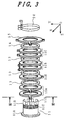
- the holder 11 is not detailed in Fig. 1, but as shown in an exploded view in perspective in Fig. 3 the holder 11 is composed of a cylindrical member to be fitted around the neck portion 1B, has a flange 11A at one end thereof, a side wall portion 11B extending from the flange 11A to the other end thereof, a threaded portion 11C to mate with a locking ring 15 to be described later, and a clamp-mounting portion 11D for fixing the cylindrical member around the neck portion 1B with a metal clamp 20.
- a pair of magnetic members 12A for producing two-pole magnetic field, a magnetic member 12X for producing four-polemagnetic field, a pair of magnetic members 12B for producing four-pole magnetic field, and a pair of magnetic members 12C for producing six-pole magnetic field in this order are slipped on the holder 11 from the side of the clamp-mounting portion 11D, with a spacer interposed between the pair 12A, the magnetic member 12X, the pair 12B and the 12C.
- the respective magnetic members are ring-shaped and can be rotated independently around the holder 11, and their detailed constitutions will be described later.
- the spacer ring 13 is so ring-shaped as to have a hole into which the holder 11 is inserted, and has a protrusion at its inner periphery which is not shown in Fig. 3.
- the protrusion of the space ring 13 slipped on the holder 11 engages with a groove (not shown) extending in the Z axis direction on the outer side wall of the holder 11, and suppresses the rotation of the spacer ring 13. In other words, when a magnetic member is rotated, the spacer ring13 prevents the rotation of other magnetic members adjacent to the magnetic member.
- a locking ring 15 is mounted on the holder 11 with a spacer ring 14 of the shape similar to that of the spacer ring 13, interposed between the magnetic members and the locking ring 15.
- the locking ring 15 has a threaded inner surface to mate with a threaded portion 11C of the holder 11.
- Each of the magnetic members 12A for producing two-pole magnetic field has a tab 12P as shown in Fig. 4, a cross sectional view taken on line - of Fig. 3.
- the magnetic members 12A can be rotated around the neck portion 1B by moving the tab 12P in the directions of arrows shown in Fig. 4.
- a tab 12P is also provided in each of the magnetic members, a magnetic member 12 for four-pole magnetic field, a pair of magnetic members 12B for four-pole magnetic field and a pair of magnetic members 12C for six-pole magnetic field.
- Magnetic members, 12A, 12B, 12X and 12C are manufactured by locally magnetizing magnetic material members or embedding a plurality of small magnet pieces at a plurality of positions in a nonmagnetic material, and the number of magnetized positions or the arrangement of the magnetized positions in the magnetic members differ with the type of the magnetic members.
- the magnetic member 12A for producing two-pole magnetic field disposes two poles of different polarities along the circumference at approximately equal intervals as shown in Fig. 5.
- the magnetic members 12B, 12X for producing four-pole magnetic field dispose four poles alternating in polarity along the circumference at approximately equal intervals as shown in Fig. 6.
- the magnetic member 12C for producing six-pole magnetic field disposes six poles alternating in polarity along the circumference at approximately equal intervals as shown in Fig. 7.
- the method of beam convergence adjustment by using magnetic members for two-pole, four-pole and six-pole magnetic fields is described in detail in U.S. Patent No. 3,725,831.
- a magnetic member in which two pieces of magnets 30 are disposed at two places as shown in Fig. 9 as a magnetic member for four-pole magnetic field in place of the magnetic members 12B or 12X for four-pole magnetic field having a magnet at four places, or to use a magnetic member in which three pieces of magnets 30 are disposed at three places as shown in Fig. 10 as a magnetic member for six-pole magnetic field in place of a magnetic member 12C for six-pole magnetic field having a magnet at six places.
- respective magnetic members, 12A, 12B, 12X and 12C are arranged to be able to rotate independently and arbitrarily around the surface of the side wall portion 11B of the holder 11. Accordingly, the dispositions of respective magnetic members are changed, thereby the magnetic field distribution in the inside of the neck portion 1B where the electron beams pass through is changed.
- the electron beams 3 when the undeflected electron beams 3 impinge on the position displaced from the center of the phosphor screen, the electron beams can be adjusted to impinge on the center of the screen by changing the above-mentioned magnetic field.
- the convergence adjustment means 7 is constituted by an insulating material such as synthetic resin except the metal fixing portion 11D, magnets embedded in a magnetic member 12, etc.
- one piece of a magnetic member 12X for producing four-pole magnetic field is added to the prior art beam convergence means.
- the added magnetic member 12X for four-pole magnetic field is disposed between the magnetic member 12A for two-pole magnetic field and a pair of magnetic members 12B for four-pole magnetic field with spacer rings 13 interposed therebetween as shown in Fig. 1 and Fig. 3.
- the arrangement of the present invention is not limited to this, and the added magnetic member 12X can be positioned between the flange 11A and the pair of magnetic members 12A for two-pole magnetic field, between the magnetic members12B for four-pole magnetic field and the magnetic members 12C for six-pole magnetic field or between the magnetic members 12C for six-pole magnetic field and the locking ring 15.
- the above-mentioned magnetic member 12X for four-pole magnetic field is adjusted independently of other magnetic members, and it is possible to increase or decrease a distance of an electron beam for red or blue with respect to an electron beam for green positioned therebetween by properly rotating the magnetic member 12X for four-pole magnetic field around the neck portion 1B.
- a magnetic member 12X for four-pole magnetic field is additionally provided, but in place of such arrangement, the following arrangement is also good in which either the spacer ring 13 or the spacer ring 14 is so configured as to provide a four-pole magnetic field by locally magnetizing or embedding magnets and to be rotated around the neck portion by a tab added to it.
- the positional relations on the display screen among the bright beam spot 4(R) on the red phosphor produced by the electron beams for red, the bright beam spot 4(G) on the phosphor film 4 produced by the electron beams for green and the beam spot 4(B) on the phosphor film 4 produced by the electron beams for blue can be changed from a state where respective spots are excessively close to each other as shown in Fig. 8A to a state as shown in Fig. 8B.
- three beam spots may be perceived as one beam spot by eyes, but in the state as shown in Fig. 8B three bright beam spots can be perceived as three separate beam spots.
- the present invention can be also utilized in a case when the red beam spot 4(R) and the blue beam spot 4(B) are excessively apart from the green beam spot 4(G), they can be brought properly close to the green beam spot (G).
- the magnetic member 12X shall be rotated by 90 degrees.
- the gun structure of a color cathode ray tube are designed to effect convergence of the three electron beams at the center of the phosphor screen. It is preferable that one gun structure can be used for a range of tube sizes and configurations for cost savings.
- an electron gun designed for a cathode ray tube of a particular tube size and configuration is used for a cathode ray tube of another tube size and configuration, a problem that three beam spots are not spaced at a proper distance from each other on the screen may occur; however, such a problem can be solved by the present invention.
- the beam convergence adjustment means 7 is provided with a pair of magnetic members for two-pole magnetic field, a pair of magnetic members for four-pole magnetic field and a pair of magnetic members for six-pole magnetic field; however an arrangement of the present invention is not limited to the one which is provided with all of them, or the one which is provided with a magnetic member having different number of poles is also good.
- the present invention makes it possible to perform accurate convergence adjustment.
Landscapes
- Video Image Reproduction Devices For Color Tv Systems (AREA)
- Manufacture Of Electron Tubes, Discharge Lamp Vessels, Lead-In Wires, And The Like (AREA)
Applications Claiming Priority (2)
| Application Number | Priority Date | Filing Date | Title |
|---|---|---|---|
| JP302714/96 | 1996-11-14 | ||
| JP30271496A JPH10144236A (ja) | 1996-11-14 | 1996-11-14 | カラー陰極線管 |
Publications (2)
| Publication Number | Publication Date |
|---|---|
| EP0843333A2 true EP0843333A2 (de) | 1998-05-20 |
| EP0843333A3 EP0843333A3 (de) | 1999-06-02 |
Family
ID=17912301
Family Applications (1)
| Application Number | Title | Priority Date | Filing Date |
|---|---|---|---|
| EP97119888A Withdrawn EP0843333A3 (de) | 1996-11-14 | 1997-11-13 | Mit einer Justiervorrichtung, zur Konvergierung eines Strahlenbündels versehene Farbkathodenstrahlröhre |
Country Status (4)
| Country | Link |
|---|---|
| EP (1) | EP0843333A3 (de) |
| JP (1) | JPH10144236A (de) |
| KR (1) | KR19980042445A (de) |
| SG (1) | SG74603A1 (de) |
Cited By (2)
| Publication number | Priority date | Publication date | Assignee | Title |
|---|---|---|---|---|
| EP1117123A1 (de) * | 1999-12-24 | 2001-07-18 | Hitachi, Ltd. | Inline-Farbbildröhre |
| EP1503397A3 (de) * | 2003-08-01 | 2006-01-04 | Matsushita Toshiba Picture Display Co., Ltd. | Farbbildröhre |
Family Cites Families (6)
| Publication number | Priority date | Publication date | Assignee | Title |
|---|---|---|---|---|
| US3725831A (en) * | 1972-01-14 | 1973-04-03 | Rca Corp | Magnetic beam adjusting arrangements |
| GB1429292A (en) * | 1972-03-20 | 1976-03-24 | Rca Corp | Static convergence device for electron beams |
| NL160427C (nl) * | 1973-09-14 | Philips Nv | Weergeefinrichting voor kleurentelevisie. | |
| US4091347A (en) * | 1976-03-17 | 1978-05-23 | Rca Corporation | Convergence apparatus for in-line beams |
| US4117433A (en) * | 1977-04-25 | 1978-09-26 | Rca Corporation | Static convergence device including magnetic corrector apparatus |
| US4670726A (en) * | 1984-12-20 | 1987-06-02 | Hitachi Metals, Ltd. | Convergence device for electron beams in color picture tube |
-
1996
- 1996-11-14 JP JP30271496A patent/JPH10144236A/ja active Pending
-
1997
- 1997-11-07 SG SG1997003983A patent/SG74603A1/en unknown
- 1997-11-13 EP EP97119888A patent/EP0843333A3/de not_active Withdrawn
- 1997-11-14 KR KR1019970060107A patent/KR19980042445A/ko not_active Abandoned
Cited By (4)
| Publication number | Priority date | Publication date | Assignee | Title |
|---|---|---|---|---|
| EP1117123A1 (de) * | 1999-12-24 | 2001-07-18 | Hitachi, Ltd. | Inline-Farbbildröhre |
| US6448706B1 (en) | 1999-12-24 | 2002-09-10 | Hitachi, Ltd. | Inline type color picture tube |
| EP1503397A3 (de) * | 2003-08-01 | 2006-01-04 | Matsushita Toshiba Picture Display Co., Ltd. | Farbbildröhre |
| US7038368B2 (en) | 2003-08-01 | 2006-05-02 | Matsushita Toshiba Picture Display Co., Ltd. | Color picture tube apparatus having a pair of bar shaped magnets for correcting misconvergence due to the rotational shift of the electron beams |
Also Published As
| Publication number | Publication date |
|---|---|
| EP0843333A3 (de) | 1999-06-02 |
| KR19980042445A (ko) | 1998-08-17 |
| SG74603A1 (en) | 2000-08-22 |
| JPH10144236A (ja) | 1998-05-29 |
Similar Documents
| Publication | Publication Date | Title |
|---|---|---|
| US3725831A (en) | Magnetic beam adjusting arrangements | |
| US3808570A (en) | Static convergence device for electron beams | |
| US4310819A (en) | Magnetic beam adjusting arrangement | |
| US3375389A (en) | Adjustable convergence magnets | |
| EP0843333A2 (de) | Mit einer Justiervorrichtung, zur Konvergierung eines Strahlenbündels versehene Farbkathodenstrahlröhre | |
| US4295110A (en) | Adjusting device for color cathode ray tube | |
| US3525962A (en) | Magnetic cap for color kinescope | |
| EP1019940B1 (de) | Halter zur Sicherung eines Ferritrings für Strahlkorrekturen in einer Kathodenstrahlröhre | |
| US6124669A (en) | Color cathode ray tube | |
| US6211610B1 (en) | Color cathode ray tube with first and second magnetic compensators | |
| EP0310242B1 (de) | Farbanzeigesystem mit selbstkonvergierendem Ablenkjoch mit Rasterverzerrungskorrektur | |
| US6268689B1 (en) | Convergence assembly including a correction ring for a color cathode ray tube | |
| US6060824A (en) | Color cathode ray tube with specific placement of magnetic plate | |
| KR100573095B1 (ko) | R/b마그네트 조립체와 이를 구비한 칼라 음극선관 | |
| EP1503397B1 (de) | Farbbildröhre | |
| US4245205A (en) | Convergence adjustment arrangement using magnetic tabs with differential motion and rotary drive | |
| KR200360755Y1 (ko) | 컬러음극선관의할로보정장치 | |
| US3624573A (en) | Blue lateral magnet structure | |
| KR100325878B1 (ko) | 콘버어젼스퓨리티마그네트조립체와이를이용한음극선관 | |
| KR960006527Y1 (ko) | 더미(dumy)자극이 추가된 음극 선관용 컨버전스 마그네트 조립체 | |
| KR100319091B1 (ko) | 음극선관의퓨리티및컨버젼스조정방법 | |
| KR830000922B1 (ko) | 집속장치 | |
| JPS5854456B2 (ja) | 集中調整装置 | |
| JPH07115656A (ja) | 陰極線管 | |
| KR20020021712A (ko) | 전자빔 포커스 보정용 마그네트 유니트 및, 그것을구비하는 칼러 음극선관 |
Legal Events
| Date | Code | Title | Description |
|---|---|---|---|
| PUAI | Public reference made under article 153(3) epc to a published international application that has entered the european phase |
Free format text: ORIGINAL CODE: 0009012 |
|
| AK | Designated contracting states |
Kind code of ref document: A2 Designated state(s): DE FR GB IT NL |
|
| PUAL | Search report despatched |
Free format text: ORIGINAL CODE: 0009013 |
|
| AK | Designated contracting states |
Kind code of ref document: A3 Designated state(s): AT BE CH DE DK ES FI FR GB GR IE IT LI LU MC NL PT SE |
|
| AKX | Designation fees paid |
Free format text: DE FR GB IT NL |
|
| STAA | Information on the status of an ep patent application or granted ep patent |
Free format text: STATUS: THE APPLICATION IS DEEMED TO BE WITHDRAWN |
|
| 18D | Application deemed to be withdrawn |
Effective date: 20000601 |