EP0842864B1 - Behälterträger - Google Patents
Behälterträger Download PDFInfo
- Publication number
- EP0842864B1 EP0842864B1 EP97309038A EP97309038A EP0842864B1 EP 0842864 B1 EP0842864 B1 EP 0842864B1 EP 97309038 A EP97309038 A EP 97309038A EP 97309038 A EP97309038 A EP 97309038A EP 0842864 B1 EP0842864 B1 EP 0842864B1
- Authority
- EP
- European Patent Office
- Prior art keywords
- engaging portion
- container engaging
- carrier
- handle portion
- tab portions
- Prior art date
- Legal status (The legal status is an assumption and is not a legal conclusion. Google has not performed a legal analysis and makes no representation as to the accuracy of the status listed.)
- Expired - Lifetime
Links
- 239000000463 material Substances 0.000 claims description 32
- 239000004033 plastic Substances 0.000 claims description 24
- 229920003023 plastic Polymers 0.000 claims description 24
- 238000000034 method Methods 0.000 claims description 15
- 239000000969 carrier Substances 0.000 claims description 7
- 238000010276 construction Methods 0.000 claims description 6
- 238000003466 welding Methods 0.000 claims description 4
- 239000002356 single layer Substances 0.000 claims description 2
- 238000007639 printing Methods 0.000 description 3
- 229920001684 low density polyethylene Polymers 0.000 description 2
- 239000004702 low-density polyethylene Substances 0.000 description 2
- 238000004519 manufacturing process Methods 0.000 description 2
- 238000007789 sealing Methods 0.000 description 2
- 239000004820 Pressure-sensitive adhesive Substances 0.000 description 1
- 235000013361 beverage Nutrition 0.000 description 1
- 230000015572 biosynthetic process Effects 0.000 description 1
- 239000003086 colorant Substances 0.000 description 1
- 238000011437 continuous method Methods 0.000 description 1
- 238000005516 engineering process Methods 0.000 description 1
- 238000005304 joining Methods 0.000 description 1
- 239000010410 layer Substances 0.000 description 1
- 238000004080 punching Methods 0.000 description 1
Images


Classifications
-
- B—PERFORMING OPERATIONS; TRANSPORTING
- B65—CONVEYING; PACKING; STORING; HANDLING THIN OR FILAMENTARY MATERIAL
- B65D—CONTAINERS FOR STORAGE OR TRANSPORT OF ARTICLES OR MATERIALS, e.g. BAGS, BARRELS, BOTTLES, BOXES, CANS, CARTONS, CRATES, DRUMS, JARS, TANKS, HOPPERS, FORWARDING CONTAINERS; ACCESSORIES, CLOSURES, OR FITTINGS THEREFOR; PACKAGING ELEMENTS; PACKAGES
- B65D71/00—Bundles of articles held together by packaging elements for convenience of storage or transport, e.g. portable segregating carrier for plural receptacles such as beer cans or pop bottles; Bales of material
- B65D71/50—Bundles of articles held together by packaging elements for convenience of storage or transport, e.g. portable segregating carrier for plural receptacles such as beer cans or pop bottles; Bales of material comprising a plurality of articles held together only partially by packaging elements formed otherwise than by folding a blank
- B65D71/504—Bundles of articles held together by packaging elements for convenience of storage or transport, e.g. portable segregating carrier for plural receptacles such as beer cans or pop bottles; Bales of material comprising a plurality of articles held together only partially by packaging elements formed otherwise than by folding a blank the element being formed from a flexible sheet provided with slits or apertures intended to be stretched over the articles and adapt to the shape of the article
Definitions
- This invention is generally directed to a plastic top lift carrier for carrying container such as bottles, cans and the like. More particularly, the invention contemplates a plastic carrier which has a handle portion that is formed separately from a planar container engaging portion. The handle portion and the container engaging portion are fused or welded together after formation of the portions.
- US-A-5,487,465 discloses a plastic carrier for carrying containers, such as cans, bottles and the like.
- the carrier is formed from two webs of plastic material juxtaposed over one another and stamped to provide the handle portion and the container engaging portion simultaneously.
- the webs are fused or welded across the juncture between the handle portion and the container engaging portion, such as by heat sealing, to form a weld.
- the resulting handle portion has a double thickness and the container engaging portions freely depend from the handle portion at the weld.
- the handle portion is of a double thickness which wastes material.
- the handle portion and the container engaging portion must be formed from the same material and the carrier portion must be symmetrical about its centerline.
- EP-A-0680893 describes a carrier for carrying a plurality of containers comprising: a plastic container engaging portion having a plurality of apertures therethrough in rows, in use, each said aperture carrying an associated container and a handle portion having a plurality of tab portions along an edge; which are secured to said container engaging portion between said rows of apertures.
- the handle again includes two separate layers, is made from cardboard and includes blunt arrowheads which fit into slots cut in the plastic container engaging portion to connect the handle portion to the container engaging portion.
- such a carrier is characterised in that said handle portion is made of plastics material, is formed by only a single layer, and is welded or fused to the container engaging portion.
- the handle portion is of a single ply of plastic material. Further different styles of the handle portion may be readily provided. Also it is possible to provide a plastic carrier which has a container engaging portion that is not identical on both sides of the carrier.
- the container engaging portion is provided with a plurality of spaced slots between the rows of apertures.
- the tab portions on the handle portion are respectively inserted through the slots and fused or welded to an underside of the container engaging portion to form a strong, peel resistant weld.
- the weld is placed in shear instead of in peel.
- the slots in the container engaging portion are eliminated and the handle portion is fused or welded directly to the upper surface of the container engaging portion.
- This embodiment of the carrier is preferably used to carry lighter items for which peel forces do not have to be substantially eliminated.
- a method of forming a carrier for use in carrying a plurality of containers comprises the steps of:
- a plurality of spaced slots are stamped between the rows of apertures. Further, during the step of overlapping the handle portion and the container engaging portion, the tab portions are inserted into and through the slots. When the tab portions are fused or welded to the container engaging portion, the tab portions are fused or welded to an underside of the container engaging portion to form a strong, peel resistant weld, with the remainder of the handle portion being above the container engaging portion. When containers are placed in the carrier and the package is carried, the weld is placed in shear, not in peel.
- the slots through the container engaging portion are eliminated. Instead, the handle portion is fused or welded to a top surface of the container engaging portion between the rows of apertures.
- This embodiment of the carrier is preferably used for lighter weight items for which peel forces do not need to be substantially eliminated.
- top lift carrier 20 which incorporates features of the present invention is shown.
- the carrier 20 is used for carrying containers 22, such as cans, bottles and the like.
- the carrier 20 is formed from a container engaging portion 24 and a handle portion 26 which are manufactured separately from each other by stamping each out of a planar sheet of material and are joined together to form the completed carrier 20, as described more fully herein.
- the container engaging portion 24 and the handle portion 26 may be, and are preferably, made of two materials which are not identical to each other. For example, a heavier weight or thicker plastic material can be used for the handle portion 26 while a lighter weight or thinner plastic material or otherwise different material than the handle portion 26 is used for the container engaging portion 24. Alternatively, the container engaging portion 24 and the handle portion 26 may be made of the same material.
- the construction of the novel carrier 20 of the present invention permits separate sheets of material to be stamped individually to respectively form the container engaging portion 24 and the handle portion 26. This permits the handle portion 26 to be pre-printed on both sides and also permits the design of the carrier 20 to have features that are not necessarily identical on each side of the centerline of the top lift carrier 20.
- the container engaging portion 24 is made from a planar blank of suitable flexible, resilient, stretchable material, such as plastic, and has a pair of rows of apertures 28 stamped therein and defined by annular bands 30 for securely holding therein the containers 22.
- the containers 22 are a plurality of typical beverage cans which are securely held within the apertures 28 in the container engaging portion 24 by the resiliently stretched bands 30.
- the container engaging portion 24 is made of a low density polyethylene so that the container engaging portion 24 can be stretched over the containers 22 and conform to the side walls of the containers 22.
- the carrier 20 may be applied to the containers 22 by known means, for example, by the machines disclosed in US-A-4,250,682 or US-A-3,204,386.
- the container engaging portion 24 has a middle section 32 between the rows of apertures 28 and outer margins 34 on the opposite sides of the rows of apertures 28.
- a plurality of spaced slots 38 each having a predetermined width are provided in the middle section 32 of the container engaging portion 24 and are generally provided between adjacent apertures 28 on each side of the portion 24.
- a plurality of generally diamond-shaped cutouts 40 are provided in the middle section 32 of the container engaging portion 24.
- Each outer margin 34 has a zipper strip 36 thereon which may be formed in accordance with, and is fully disclosed, in EP-A-0792819.
- the carrier 20 of the present invention presents an improvement to the carrier disclosed in EP-A-0792819 because the design of the carrier 20 of the present invention permits the design of the carrier to have features that are not necessarily identical on each side of the centerline of the carrier 20 as is necessary in the earlier specification.
- the design of this carrier 20 permits the zipper strip 36 to be designed to be opened from either the same direction on both sides of the carrier 20 or different directions on each side of the carrier 20.
- This carrier 20 also permits a UPC flap (not shown) to be on one outer margin 34 of the container engaging portion 24 and not on the other outer margin thereof.
- the handle portion 26 is made of a planar blank of suitable flexible, resilient, stretchable material, such as plastic, preferably low density polyethylene.
- the handle portion 26 has a body portion 42 having an aperture 44 provided through an upper portion of the body portion 42 proximate one edge of the body portion 42 so that a user's hand can be inserted through the aperture 44 to grasp the handle portion 26.
- a plurality of spaced tab portions 46 are provided on the opposite edge of the body portion 42 and protrude from the remainder of the body portion 42.
- the tab portions 46 are spaced apart from each other approximately the same distance that the slots 38 provided through the container engaging portion 24 are spaced and have a predetermined width which is approximately the same as the width of the slots 38.
- a plurality of openings 48 are formed through the body portion 42 proximate to the edge on which the tab portions 46 are provided.
- each tab portion 46 on the handle portion 26 is inserted into and through one of the spaced slots 38 in the container engaging portion 24. Thereafter, the tab portions 46 are fused or welded to the underside of the container engaging portion 24 by suitable means.
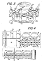
- the carrier 20 is formed in a continuous method.
- a roll 50 of plastic material provides a first web 52 which is used to form the handle portion 26 and a roll 54 of plastic material provides a second web 56 which is used to form the container engaging portion 24.
- These webs 52, 54 may be the same material or different materials.
- the webs 52, 54 may be the same colour or dissimilar colours such that the resulting carrier 20 is natural, tinted or pigmented.
- the web of material 54 which is used to form the handle portion 26 may be printed on by a suitable printing means 58.
- the handle portion 26 can be printed on one side or on both sides thereof in registration.
- a suitable printing means can be provided to print on the container engaging portion 24, for example to form a bar code on the UPC flap (not shown).
- Each web 52, 56 is then punched separately by a punch press die 60, 62 of known construction, to form separate continuous strips of container engaging portions 24 and handle portions 26.
- the punch press die 60 forms all of the apertures 28, the zipper strip features and the slots 38 through the middle section 32 of the container engaging portion 24.
- Each container engaging portion 24 is integrally connected to the adjacent container engaging portion at the ends thereof.
- the punch press die 62 forms the tab portions 46 and all of the apertures and openings 44, 48 in the handle portion 26.
- Each handle portion 26 is integrally connected to the adjacent handle portion at the ends thereof.
- the separate punching of the container engaging portion 24 and the handle portion 26 allows for a unique container engaging portion 24 and handle portion 26.
- the handle portion 26 can be readily changed to accommodate unique customer designs while using the container engaging portion 24, or a variation of the container engaging portion 24, disclosed herein. Smaller runs of the handle portion 26 can be run on less expensive tooling in a rotary, whereas the container engaging portion 24 can be run on a punch press die at three or four across.
- any combination of UPC flaps or opening features can be designed into the container engaging portion 24.
- each handle portion 26 is moved by suitable means to join with the respective container engaging portion 24 by inserting the tab portions 46 into and through the slots 38 between the rows of apertures 28 such that the tab portions 46 are beneath the container engaging portion 24 and the remainder of the handle portion 26 is generally above the container engaging portion 24. During this process, the handle portions 26 and container engaging portions 24 remain flattened against each other.
- the handle portion 26 and the container engaging portion 24 are joined together along the middle section 32 of the container engaging portion 24 such that the tab portions 46 are fused or welded to the underside of the container engaging portion 24 to form a weld 64 between the tab portions 46 and the container engaging portion 24.
- the joining is effected by suitable means, such as by heat sealing using a heated roller 66. It should also be recognized that in some cases, a strip of heat sensitive or pressure sensitive adhesive may be inserted at desired locations between the container engaging portion 24 and the handle portion 26 to secure the tab portions 46 to the underside of the container engaging portion 24.
- the continuous web of completed carriers 20 are then rolled into a roll 68 on a reel or otherwise appropriately stored until they are to be applied to containers by known methods.
- the structure and process of this invention thus provides degrees of manufacturing flexibility to produce integral carriers having features not capable of being created using existing technology.
- the printing on the handle portion 26 may be done after the handle portion has been stamping by the punch press die 62. If the same material is being used to form both of the container engaging portion 24 and the handle portion 26, the same punch press die can be used to form both.
- the strip of container engaging portions 24 and the strip of handle portions 26 may be separately wound into rolls and then only assembled together prior to use.
- an individual carrier 20 is separated from the roll 68 by suitable means.
- the carrier 20 is then stretched over the containers 22 using known means.
- the handle portion 26 is pivoted upwardly so as to extend upwardly between the rows of containers 22 and is generally perpendicular to the container engaging portion 24 of the carrier 20.
- the fusing or welding of the tab portions 46 on the underside of the container engaging portion 24 permits the weld 64 to be in shear and not in peel, thereby forming a stronger bond between the handle portion 26 and the container engaging portion 24.
- the container engaging portion 24 and the handle portion 26 are formed separately and may be formed from dissimilar materials or be of dissimilar thicknesses, the material used for the container engaging portion 24 and the handle portion 26 can be optimized.
- the handle portion 24 may be formed from a stronger plastic material than what is used to form the container engaging portion 26 so that the handle portion 26 will not tear from the weight of the containers 22.
- the single ply handle portion 26 allows for a material cost savings over double ply handles provided in prior art carrier handles.
- the second embodiment of the carrier 20a is identical in construction to the first embodiment of the carrier 20 shown in Figure 1 and provides all of the same advantages as described with respect to the first embodiment, except for the differences noted hereinbelow.
- the components of the carrier 20a which are identical to the carrier 20 are identified with the same numerals but with the suffix "a" after the reference numeral.
- the slots 38 through the middle section of the container engaging portion provided in the first embodiment of the carrier 20 have been eliminated.
- the tab portions 46a are fused or welded directly to the top surface of the container engaging portion 24a along the middle section 32a thereof to form a weld 64a, see Figure 7, at the same positions that the slots would have been provided.
- This carrier 20a is preferably used to carry lighter items in which peel forces do not need to be substantially eliminated.
- the handle portion 26 is pivoted upwardly so as to extend upwardly between the rows of containers 22 and is generally perpendicular to the container engaging portion 24a of the carrier 20a.
- Each tab portion 46a may be provided with a score line 72 at the juncture between the respective tab portion 46a and the remainder of the handle portion 26a to provide a crease, thereby aiding the handle portion 26a to move upwardly.
- the method of forming the carriers 20a is identical to that described with respect to the first embodiment of the carrier 20 as shown in Figure 4, except for the differences noted hereinbelow. When the container engaging portion 24a is punched by the punch press die 60, the portion 24a is identical to that of the first embodiment except that the slots 38 provided in the first embodiment are not formed.
- each handle portion 26a is moved by suitable means to join with the respective container engaging portion 24a, the tab portions 46a are laid over the middle section 32a of the container engaging portion 24a between the rows of apertures 28a such that the tab portions 46a are on top of the container engaging portion 24a.
- the handle portions 26a and container engaging portions 24a remain flattened against each other.
- the tab portions 46a of the handle portion 26a are fused or welded to the container engaging portion 24a along the middle section 32a thereof, the tab portions 46a are fused or welded on top of the container engaging portion 24a to form a weld 64a between the tab portions 46a and the container engaging portion 24a.
Landscapes
- Engineering & Computer Science (AREA)
- Mechanical Engineering (AREA)
- Packages (AREA)
- Details Of Rigid Or Semi-Rigid Containers (AREA)
Claims (10)
- Träger (20) zum Tragen mehrerer Behälter (22), mit einem Behälter-Aufnahmeabschnitt (24) aus Kunststoff mit mehreren hindurchgehenden Öffnungen (28) in Reihen, wobei in Gebrauch jede der Öffnungen (28) einen zugehörigen Behälter (22) trägt, und mit einem Griffabschnitt (26) mit mehreren Laschenabschnitten (46) entlang einer Kante, die an dem Behälter-Aufnahmeabschnitt (24) zwischen den Reihen von Öffnungen (28) angebracht sind, dadurch gekennzeichnet, dass der Griffabschnitt (26) aus Kunststoffmaterial besteht, aus nur einer einzigen Lage gebildet ist, und an den Behälter-Aufnahmeabschnitt (24) angeschweißt oder angeschmolzen ist.
- Träger nach Anspruch 1, wobei der Griffabschnitt (26) an eine obere Fläche des Behälter-Aufnahmeabschnitts (24) angeschweißt oder angeschmolzen ist.
- Träger nach Anspruch 1, wobei in dem Behälter-Aufnahmeabschnitt (24) des Weiteren mehrere beabstandete Schlitze (38) zwischen den Reihen von Öffnungen (28) ausgebildet sind, wobei jeder der Laschenabschnitte (46) durch einen entsprechenden Schlitz (38) im Behälter-Aufnahmeabschnitt eingesetzt und an eine Unterseite des Behälter-Aufnahmeabschnittes (24) angeschweißt oder angeschmolzen ist, um eine Schweißstelle zu bilden, so dass die Laschenabschnitte (38) im Wesentlichen unter dem Behälter-Aufnahmeabschnitt (24) liegen und der Rest des Griffabschnittes (26) im Wesentlichen über dem Behälter-Aufnahmeabschnitt (24) liegt, wodurch die Schweißstelle einem Schub ausgesetzt wird, wenn sich der Träger (20) in Verwendung befindet.
- Träger nach einem der vorangehenden Ansprüche, wobei der Behälter-Aufnahmeabschnitt (24) äußere Ränder aufweist und des Weiteren an jedem Außenrand einen Reißverschlussstreifen (36) aufweist, die in der Konstruktion gleich oder ungleich sind, zur Freigabe von Behältern, die in den Öffnungen (28) in dem Behälter-Aufnahmeabschnitt (24) gehalten sind.
- Träger nach einem der vorangehenden Ansprüche, wobei der Griffabschnitt (26) und der Behälter-Aufnahmeabschnitt (24) nicht aus identischen Kunststoffmaterialien hergestellt sind und/oder wobei der Griffabschnitt (26) an beiden Seiten bedruckt ist.
- Verfahren zur Ausbildung eines Trägers (20) zur Verwendung beim Tragen mehrerer Behälter (22), umfassend die Schritte:Stanzen eines Griffabschnittes (26) mit mehreren Laschenabschnitten (46) an einer Kante desselben aus einer einfachen Schicht eines Kunststoffmaterials (56),Stanzen eines Behälter-Aufnahmeabschnittes (24) mit mehreren hindurchgehenden Öffnungen (28) in Reihen aus einem Kunststoffmaterial (52), so dass der Behälter-Aufnahmeabschnitt (24) von dem Griffabschnitt (26) getrennt vorliegt,Auflegen des Griffabschnittes (26) auf den Behälter-Aufnahmeabschnitt (24), so dass die Laschenabschnitte (46) zwischen den Reihen von Öffnungen (28) positioniert sind, undSchweißen oder Anschmelzen der Laschenabschnitte (46) an den Behälter-Aufnahmeabschnitt (24) zwischen den Reihen von Öffnungen (28) zum Bilden des fertigen Trägers (20).
- Verfahren nach Anspruch 6, wobei während des Schrittes des Schweißens oder Anschmelzens der Laschenabschnitte (46) an den Behälter-Aufnahmeabschnitt (24) die Laschenabschnitte (46) an eine obere Fläche des Behälter-Aufnahmeabschnitts (24) angeschmolzen werden.
- Verfahren nach Anspruch 6, wobei während des Schrittes des Stanzens des Behälter-Aufnahmeabschnitts (24) mehrere beabstandete Schlitze (38) zwischen den Reihen von Öffnungen (28) gestanzt werden, und wobei während des Schrittes des Auflegens des Griffabschnittes (26) auf den Behälter-Aufnahmeabschnitt (24) die Laschenabschnitte (46) durch die Schlitze (38) so eingesetzt werden, dass die Laschenabschnitte (46) zwischen den Reihen von Öffnungen (28) derart positioniert sind, dass die Laschenabschnitte (46) danach an eine Unterseite des Behälter-Aufnahmeabschnittes (24) angeschmolzen werden, wobei der Rest des Griffabschnittes (26) während des Schrittes des Anschmelzens der Laschenabschnitte (46) an den Behälter-Aufnahmeabschnitt (24) im Wesentlichen über dem Behälter-Aufnahmeabschnitt (24) liegt.
- Verfahren nach Anspruch 6, 7 oder 8, des Weiteren umfassend den Schritt des Bereitstellens wenigstens einer Rolle (50, 54) von Kunststoffmaterial zum Stanzen des Griffabschnittes (26) und des Behälter-Aufnahmeabschnittes (24), und wobei mehrere Träger (20) kontinuierlich gebildet werden, so dass jeder Träger (20) mit benachbarten Trägern verbunden ist.
- Verfahren nach Anspruch 9, des Weiteren umfassend den Schritt des Sammelns der fertigen Träger (20) auf einer Rolle.
Applications Claiming Priority (2)
| Application Number | Priority Date | Filing Date | Title |
|---|---|---|---|
| US08/747,612 US5868659A (en) | 1996-11-13 | 1996-11-13 | Method of forming a two-piece fused top lift carrier |
| US747612 | 1996-11-13 |
Publications (2)
| Publication Number | Publication Date |
|---|---|
| EP0842864A1 EP0842864A1 (de) | 1998-05-20 |
| EP0842864B1 true EP0842864B1 (de) | 2004-03-03 |
Family
ID=25005870
Family Applications (1)
| Application Number | Title | Priority Date | Filing Date |
|---|---|---|---|
| EP97309038A Expired - Lifetime EP0842864B1 (de) | 1996-11-13 | 1997-11-11 | Behälterträger |
Country Status (16)
| Country | Link |
|---|---|
| US (2) | US5868659A (de) |
| EP (1) | EP0842864B1 (de) |
| JP (1) | JPH10181767A (de) |
| CN (1) | CN1079772C (de) |
| AR (1) | AR010582A1 (de) |
| AT (1) | ATE260830T1 (de) |
| AU (1) | AU697820B2 (de) |
| BR (1) | BR9705373A (de) |
| CA (1) | CA2219804C (de) |
| DE (1) | DE69727887T2 (de) |
| DK (1) | DK0842864T3 (de) |
| ES (1) | ES2216113T3 (de) |
| NO (1) | NO975202L (de) |
| NZ (1) | NZ329127A (de) |
| PT (1) | PT842864E (de) |
| TW (1) | TW401366B (de) |
Families Citing this family (31)
| Publication number | Priority date | Publication date | Assignee | Title |
|---|---|---|---|---|
| US6006902A (en) * | 1998-09-25 | 1999-12-28 | Illinois Tool Works Inc. | Multiple modules container carrier |
| US6598738B2 (en) | 1998-09-25 | 2003-07-29 | Illinois Tool Works Inc. | Multiple property container carrier |
| AU739973B2 (en) * | 1998-09-25 | 2001-10-25 | Illinois Tool Works Inc. | Multiple modulus container carrier |
| US6182821B1 (en) * | 1998-11-24 | 2001-02-06 | Illinois Tool Works Inc. | Divisible container carrier |
| US6122893A (en) * | 1998-12-22 | 2000-09-26 | Illinois Tool Works Inc. | System and apparatus for packaging a uniform group of container having a range of diameters |
| US6484566B1 (en) | 2000-05-18 | 2002-11-26 | Rheologics, Inc. | Electrorheological and magnetorheological fluid scanning rheometer |
| US6334531B1 (en) | 2000-06-09 | 2002-01-01 | Maria Agneza Valkovich | Plastic bottle carrier |
| US6964144B1 (en) | 2000-11-16 | 2005-11-15 | Illinois Tool Works Inc. | System and apparatus for packaging containers |
| US6779655B2 (en) | 2001-10-31 | 2004-08-24 | Illinois Tool Works Inc. | Label panel container carrier with integral handle |
| FR2841223B1 (fr) * | 2002-06-19 | 2004-10-15 | Sleever Int | Enveloppe d'emballage d'objets(s) en materiau thermoretractable a face interne ou externe essentiellement lisse |
| US6969098B2 (en) * | 2002-07-03 | 2005-11-29 | Illinois Tool Works Inc. | Non-elevating handle for center lift carrier |
| US20040055905A1 (en) * | 2002-09-20 | 2004-03-25 | Marco Leslie S. | Container package with carrier and surrounding sleeve |
| AU2011253876B2 (en) * | 2003-10-08 | 2013-06-20 | Illinois Tool Works Inc. | Top lift carrier and method of manufacture therefor |
| US8545375B2 (en) * | 2003-10-08 | 2013-10-01 | Illinois Tool Works, Inc. | Top lift carrier and method of manufacture therefor |
| US20050241963A1 (en) * | 2004-04-30 | 2005-11-03 | Slomski Edward J | Dividable container carrier |
| US6978888B1 (en) * | 2004-08-25 | 2005-12-27 | Display Industries, Llc. | Bottle carrier with handle and pull tab |
| GB0421075D0 (en) * | 2004-09-22 | 2004-10-27 | Meadwestvaco Packaging Systems | Packaging method for multi-piece carton formation and apparatus for carrying out the same |
| US7510074B2 (en) * | 2004-12-08 | 2009-03-31 | Illinois Tool Works Inc. | Flexible carrier |
| DE602004010690T2 (de) * | 2004-12-13 | 2008-04-30 | Bülent Baylav | Ein Schutzträger und Handgriff für Dosen |
| US7331622B2 (en) * | 2005-02-28 | 2008-02-19 | Roberts Polypro, Inc. | Oil container carrier |
| US20060289315A1 (en) | 2005-03-07 | 2006-12-28 | Robert Olsen | Container carrier |
| US7510075B2 (en) * | 2005-03-07 | 2009-03-31 | Illinois Tool Works Inc. | Container carrier |
| US7775348B2 (en) * | 2006-02-08 | 2010-08-17 | Illinois Tool Works Inc. | Divisible container carrier |
| US7445114B2 (en) * | 2006-02-08 | 2008-11-04 | Illinois Tool Works, Inc. | Divisible container carrier |
| US20080203204A1 (en) * | 2007-02-22 | 2008-08-28 | Olsen Robert C | Cup carrier |
| US9004279B2 (en) * | 2012-07-24 | 2015-04-14 | Illinois Tool Works Inc. | Pill container carrier |
| US20150328920A1 (en) * | 2014-05-14 | 2015-11-19 | Up With Paper, LLC | Method of forming a multilayer cut out structure |
| US10166690B2 (en) * | 2015-03-17 | 2019-01-01 | Illinois Tool Works Inc. | Apparatus for producing container carriers |
| US11434058B2 (en) * | 2015-12-03 | 2022-09-06 | Illinois Tool Works Inc. | Divisible container carrier |
| PT3774574T (pt) | 2018-04-05 | 2022-04-13 | British Polythene Ltd | Melhorias em ou relacionadas com transportadores de recipientes |
| BE1027706B1 (nl) * | 2019-07-16 | 2021-05-25 | Anheuser Busch Inbev Nv | Driedimensionale drager met aangepaste lippen |
Family Cites Families (25)
| Publication number | Priority date | Publication date | Assignee | Title |
|---|---|---|---|---|
| US2826299A (en) * | 1955-11-30 | 1958-03-11 | American Can Co | Carrying handle for tied together containers |
| US2935355A (en) * | 1957-08-09 | 1960-05-03 | American Can Co | Carrying handle for containers |
| US2997169A (en) * | 1958-02-06 | 1961-08-22 | Illinois Tool Works | Container-carrier device |
| US3016136A (en) * | 1959-02-24 | 1962-01-09 | Illinois Tool Works | Handle device |
| US3038602A (en) * | 1959-12-10 | 1962-06-12 | Illinois Tool Works | Container carrier |
| US3204386A (en) | 1962-02-19 | 1965-09-07 | Illinois Tool Works | Container pack forming machine |
| US3186544A (en) * | 1962-02-23 | 1965-06-01 | Byron V Curry | Multiple container package and carrier |
| US3383827A (en) * | 1965-12-10 | 1968-05-21 | Owens Illinois Inc | Multi-pack container carrier and method of assembling to containers |
| US3700276A (en) * | 1971-02-23 | 1972-10-24 | Illinois Tool Works | Multiple container carrier |
| US3822012A (en) * | 1972-07-14 | 1974-07-02 | Illinois Tool Works | Multiple container package arrangements |
| US4250682A (en) | 1979-07-19 | 1981-02-17 | Illinois Tool Works Inc. | Wheel assembly for use in an apparatus for multipackaging containers |
| US4269314A (en) * | 1979-08-10 | 1981-05-26 | The Coca-Cola Company | Elastic band and handle structure for forming packages of groups of containers |
| US4564106A (en) * | 1983-05-06 | 1986-01-14 | Waddingtons Limited | Lifting device with tongue flaps |
| GB2163344A (en) * | 1984-08-21 | 1986-02-26 | Jeng Tian Chyuan | Carrier for bottles |
| US5115910A (en) * | 1990-06-14 | 1992-05-26 | Illinois Tool Works Inc. | Carrier stock with tear-open band segments |
| US5193673A (en) * | 1991-04-12 | 1993-03-16 | Thomas Rathbone | Environmentally safe holder device |
| US5174441A (en) * | 1991-04-17 | 1992-12-29 | Illinois Tool Works Inc. | Tear-open container carrier |
| US5265718A (en) * | 1992-05-29 | 1993-11-30 | Illinois Tool Works Inc. | Package comprising multiple containers, such as beverage cans |
| US5487465A (en) * | 1994-04-20 | 1996-01-30 | Illinois Tool Works Inc. | Container carrier |
| US5437364A (en) * | 1994-05-05 | 1995-08-01 | Illinois Tool Works Inc. | Package comprising containers, carrier, and handle |
| US5467870A (en) * | 1994-10-03 | 1995-11-21 | Illinois Tool Works Inc. | Wrapper, carrier, and handle assembly and package comprising same and containers |
| AU678924B2 (en) * | 1995-02-21 | 1997-06-12 | Illinois Tool Works Inc. | Tear strip for side handle carrier |
| US5593026A (en) * | 1995-02-21 | 1997-01-14 | Illinois Tool Works Inc. | Ring container multipack with perforated tear strip for container removal |
| US5655654A (en) * | 1995-02-21 | 1997-08-12 | Illinois Tool Works Inc. | Top lift container carrier with extendable carrier |
| US5642808A (en) | 1996-02-28 | 1997-07-01 | Illinois Tool Works Inc. | Individual aperture--continuous zip strip |
-
1996
- 1996-11-13 US US08/747,612 patent/US5868659A/en not_active Expired - Lifetime
-
1997
- 1997-10-31 CA CA002219804A patent/CA2219804C/en not_active Expired - Fee Related
- 1997-11-07 TW TW086116591A patent/TW401366B/zh not_active IP Right Cessation
- 1997-11-07 NZ NZ329127A patent/NZ329127A/en unknown
- 1997-11-11 PT PT97309038T patent/PT842864E/pt unknown
- 1997-11-11 AT AT97309038T patent/ATE260830T1/de not_active IP Right Cessation
- 1997-11-11 EP EP97309038A patent/EP0842864B1/de not_active Expired - Lifetime
- 1997-11-11 DE DE69727887T patent/DE69727887T2/de not_active Expired - Fee Related
- 1997-11-11 ES ES97309038T patent/ES2216113T3/es not_active Expired - Lifetime
- 1997-11-11 DK DK97309038T patent/DK0842864T3/da active
- 1997-11-12 AR ARP970105276A patent/AR010582A1/es unknown
- 1997-11-12 NO NO975202A patent/NO975202L/no not_active Application Discontinuation
- 1997-11-12 BR BR9705373A patent/BR9705373A/pt not_active IP Right Cessation
- 1997-11-12 AU AU45116/97A patent/AU697820B2/en not_active Ceased
- 1997-11-12 CN CN97122543A patent/CN1079772C/zh not_active Expired - Fee Related
- 1997-11-13 JP JP9312038A patent/JPH10181767A/ja active Pending
-
1998
- 1998-11-09 US US09/189,087 patent/US6152508A/en not_active Expired - Fee Related
Also Published As
| Publication number | Publication date |
|---|---|
| DK0842864T3 (da) | 2004-07-05 |
| NO975202D0 (no) | 1997-11-12 |
| ATE260830T1 (de) | 2004-03-15 |
| TW401366B (en) | 2000-08-11 |
| DE69727887T2 (de) | 2005-01-05 |
| PT842864E (pt) | 2004-06-30 |
| BR9705373A (pt) | 1998-12-22 |
| AR010582A1 (es) | 2000-06-28 |
| AU4511697A (en) | 1998-05-21 |
| US6152508A (en) | 2000-11-28 |
| CN1079772C (zh) | 2002-02-27 |
| CA2219804C (en) | 2002-12-17 |
| NZ329127A (en) | 1998-05-27 |
| DE69727887D1 (de) | 2004-04-08 |
| CN1182034A (zh) | 1998-05-20 |
| US5868659A (en) | 1999-02-09 |
| AU697820B2 (en) | 1998-10-15 |
| EP0842864A1 (de) | 1998-05-20 |
| CA2219804A1 (en) | 1998-05-13 |
| ES2216113T3 (es) | 2004-10-16 |
| NO975202L (no) | 1998-05-14 |
| MX9708533A (es) | 1998-05-31 |
| JPH10181767A (ja) | 1998-07-07 |
Similar Documents
| Publication | Publication Date | Title |
|---|---|---|
| EP0842864B1 (de) | Behälterträger | |
| EP0678456B1 (de) | Behälterträger | |
| US4790670A (en) | Bag with closeable flap and method of manufacturing same | |
| EP1255678B1 (de) | Gefalteter, aus plastik bestehender sack | |
| US6162158A (en) | Method of fabricating a sleeve label with multilayered integral flaps | |
| EP0842865B1 (de) | Behälterträger | |
| US5976294A (en) | Method of forming rolls of ribbons including peelable lid shapes with bent-back lift tabs | |
| EP0417252B1 (de) | Rechteckige kartonverpackung | |
| KR101045594B1 (ko) | 용기 캐리어와 그 용기 캐리어 제조방법 | |
| US3987711A (en) | Formation of laminated packaging blanks | |
| US3883068A (en) | Moisture barrier package formed from laminated blank | |
| US5250018A (en) | Method of making rectangular paperboard package | |
| KR100254864B1 (ko) | 컨테이너 운반용 캐리어 및 컨테이너 운반용 캐리어 형성방법 | |
| MXPA97008533A (en) | Carrier with a top cover that lets up, two pieces fundi | |
| GB2067506A (en) | Identity band | |
| EP1040911B1 (de) | Verfahren und vorrichtung zum herstellen von behältern aus einer vielzahl von streifen und behälter |
Legal Events
| Date | Code | Title | Description |
|---|---|---|---|
| PUAI | Public reference made under article 153(3) epc to a published international application that has entered the european phase |
Free format text: ORIGINAL CODE: 0009012 |
|
| AK | Designated contracting states |
Kind code of ref document: A1 Designated state(s): AT BE CH DE DK ES FI FR GB GR IE IT LI LU NL PT SE |
|
| AX | Request for extension of the european patent |
Free format text: AL;LT;LV;MK;RO;SI |
|
| 17P | Request for examination filed |
Effective date: 19981118 |
|
| AKX | Designation fees paid |
Free format text: AT BE CH DE DK ES FI FR GB GR IE IT LI LU NL PT SE |
|
| RBV | Designated contracting states (corrected) |
Designated state(s): AT BE CH DE DK ES FI FR GB GR IE IT LI LU NL PT SE |
|
| 17Q | First examination report despatched |
Effective date: 20020213 |
|
| GRAH | Despatch of communication of intention to grant a patent |
Free format text: ORIGINAL CODE: EPIDOS IGRA |
|
| GRAS | Grant fee paid |
Free format text: ORIGINAL CODE: EPIDOSNIGR3 |
|
| GRAA | (expected) grant |
Free format text: ORIGINAL CODE: 0009210 |
|
| AK | Designated contracting states |
Kind code of ref document: B1 Designated state(s): AT BE CH DE DK ES FI FR GB GR IE IT LI LU NL PT SE |
|
| REG | Reference to a national code |
Ref country code: GB Ref legal event code: FG4D |
|
| REG | Reference to a national code |
Ref country code: SE Ref legal event code: TRGR |
|
| REG | Reference to a national code |
Ref country code: CH Ref legal event code: NV Representative=s name: E. BLUM & CO. PATENTANWAELTE Ref country code: CH Ref legal event code: EP |
|
| REG | Reference to a national code |
Ref country code: IE Ref legal event code: FG4D |
|
| REF | Corresponds to: |
Ref document number: 69727887 Country of ref document: DE Date of ref document: 20040408 Kind code of ref document: P |
|
| REG | Reference to a national code |
Ref country code: GR Ref legal event code: EP Ref document number: 20040401700 Country of ref document: GR |
|
| REG | Reference to a national code |
Ref country code: PT Ref legal event code: SC4A Free format text: AVAILABILITY OF NATIONAL TRANSLATION Effective date: 20040429 |
|
| REG | Reference to a national code |
Ref country code: DK Ref legal event code: T3 |
|
| REG | Reference to a national code |
Ref country code: ES Ref legal event code: FG2A Ref document number: 2216113 Country of ref document: ES Kind code of ref document: T3 |
|
| ET | Fr: translation filed | ||
| PG25 | Lapsed in a contracting state [announced via postgrant information from national office to epo] |
Ref country code: LU Free format text: LAPSE BECAUSE OF NON-PAYMENT OF DUE FEES Effective date: 20041111 |
|
| PLBE | No opposition filed within time limit |
Free format text: ORIGINAL CODE: 0009261 |
|
| STAA | Information on the status of an ep patent application or granted ep patent |
Free format text: STATUS: NO OPPOSITION FILED WITHIN TIME LIMIT |
|
| 26N | No opposition filed |
Effective date: 20041206 |
|
| REG | Reference to a national code |
Ref country code: CH Ref legal event code: PFA Owner name: ILLINOIS TOOL WORKS INC. Free format text: ILLINOIS TOOL WORKS INC.#3600 WEST LAKE AVENUE#GLENVIEW, ILLINOIS 60025 (US) -TRANSFER TO- ILLINOIS TOOL WORKS INC.#3600 WEST LAKE AVENUE#GLENVIEW, ILLINOIS 60025 (US) |
|
| PGFP | Annual fee paid to national office [announced via postgrant information from national office to epo] |
Ref country code: NL Payment date: 20081124 Year of fee payment: 12 Ref country code: IE Payment date: 20081125 Year of fee payment: 12 Ref country code: DK Payment date: 20081125 Year of fee payment: 12 Ref country code: CH Payment date: 20081125 Year of fee payment: 12 |
|
| PGFP | Annual fee paid to national office [announced via postgrant information from national office to epo] |
Ref country code: PT Payment date: 20081021 Year of fee payment: 12 Ref country code: FI Payment date: 20081128 Year of fee payment: 12 Ref country code: ES Payment date: 20081126 Year of fee payment: 12 Ref country code: AT Payment date: 20081021 Year of fee payment: 12 |
|
| PGFP | Annual fee paid to national office [announced via postgrant information from national office to epo] |
Ref country code: SE Payment date: 20081128 Year of fee payment: 12 Ref country code: IT Payment date: 20081126 Year of fee payment: 12 |
|
| PGFP | Annual fee paid to national office [announced via postgrant information from national office to epo] |
Ref country code: FR Payment date: 20081117 Year of fee payment: 12 |
|
| PGFP | Annual fee paid to national office [announced via postgrant information from national office to epo] |
Ref country code: DE Payment date: 20081223 Year of fee payment: 12 |
|
| PGFP | Annual fee paid to national office [announced via postgrant information from national office to epo] |
Ref country code: GR Payment date: 20081127 Year of fee payment: 12 Ref country code: GB Payment date: 20081128 Year of fee payment: 12 |
|
| PGFP | Annual fee paid to national office [announced via postgrant information from national office to epo] |
Ref country code: BE Payment date: 20090128 Year of fee payment: 12 |
|
| REG | Reference to a national code |
Ref country code: PT Ref legal event code: MM4A Free format text: LAPSE DUE TO NON-PAYMENT OF FEES Effective date: 20100511 |
|
| BERE | Be: lapsed |
Owner name: ILLINOIS *TOOL WORKS INC. Effective date: 20091130 |
|
| REG | Reference to a national code |
Ref country code: NL Ref legal event code: V1 Effective date: 20100601 |
|
| EUG | Se: european patent has lapsed | ||
| REG | Reference to a national code |
Ref country code: CH Ref legal event code: PL |
|
| REG | Reference to a national code |
Ref country code: DK Ref legal event code: EBP |
|
| GBPC | Gb: european patent ceased through non-payment of renewal fee |
Effective date: 20091111 |
|
| PG25 | Lapsed in a contracting state [announced via postgrant information from national office to epo] |
Ref country code: PT Free format text: LAPSE BECAUSE OF NON-PAYMENT OF DUE FEES Effective date: 20100511 |
|
| REG | Reference to a national code |
Ref country code: IE Ref legal event code: MM4A |
|
| REG | Reference to a national code |
Ref country code: FR Ref legal event code: ST Effective date: 20100730 |
|
| PG25 | Lapsed in a contracting state [announced via postgrant information from national office to epo] |
Ref country code: FI Free format text: LAPSE BECAUSE OF NON-PAYMENT OF DUE FEES Effective date: 20091111 Ref country code: AT Free format text: LAPSE BECAUSE OF NON-PAYMENT OF DUE FEES Effective date: 20091111 |
|
| PG25 | Lapsed in a contracting state [announced via postgrant information from national office to epo] |
Ref country code: NL Free format text: LAPSE BECAUSE OF NON-PAYMENT OF DUE FEES Effective date: 20100601 Ref country code: LI Free format text: LAPSE BECAUSE OF NON-PAYMENT OF DUE FEES Effective date: 20091130 Ref country code: IE Free format text: LAPSE BECAUSE OF NON-PAYMENT OF DUE FEES Effective date: 20091111 Ref country code: GR Free format text: LAPSE BECAUSE OF NON-PAYMENT OF DUE FEES Effective date: 20100602 Ref country code: FR Free format text: LAPSE BECAUSE OF NON-PAYMENT OF DUE FEES Effective date: 20091130 Ref country code: CH Free format text: LAPSE BECAUSE OF NON-PAYMENT OF DUE FEES Effective date: 20091130 Ref country code: BE Free format text: LAPSE BECAUSE OF NON-PAYMENT OF DUE FEES Effective date: 20091130 |
|
| PG25 | Lapsed in a contracting state [announced via postgrant information from national office to epo] |
Ref country code: DE Free format text: LAPSE BECAUSE OF NON-PAYMENT OF DUE FEES Effective date: 20100601 |
|
| PG25 | Lapsed in a contracting state [announced via postgrant information from national office to epo] |
Ref country code: GB Free format text: LAPSE BECAUSE OF NON-PAYMENT OF DUE FEES Effective date: 20091111 |
|
| PG25 | Lapsed in a contracting state [announced via postgrant information from national office to epo] |
Ref country code: DK Free format text: LAPSE BECAUSE OF NON-PAYMENT OF DUE FEES Effective date: 20091130 |
|
| REG | Reference to a national code |
Ref country code: ES Ref legal event code: FD2A Effective date: 20110310 |
|
| PG25 | Lapsed in a contracting state [announced via postgrant information from national office to epo] |
Ref country code: IT Free format text: LAPSE BECAUSE OF NON-PAYMENT OF DUE FEES Effective date: 20091111 |
|
| PG25 | Lapsed in a contracting state [announced via postgrant information from national office to epo] |
Ref country code: SE Free format text: LAPSE BECAUSE OF NON-PAYMENT OF DUE FEES Effective date: 20091112 |
|
| PG25 | Lapsed in a contracting state [announced via postgrant information from national office to epo] |
Ref country code: ES Free format text: LAPSE BECAUSE OF NON-PAYMENT OF DUE FEES Effective date: 20110309 |
|
| PG25 | Lapsed in a contracting state [announced via postgrant information from national office to epo] |
Ref country code: ES Free format text: LAPSE BECAUSE OF NON-PAYMENT OF DUE FEES Effective date: 20091112 |